Facing a bottleneck in your Embedded Display Project?
Don’t let complex integration or supply chain issues slow your time-to-market. Book a free consultation with the RJY expert team for tailored design and manufacturing support.

Modern LCDs are intricate assemblies of precise optical, electronic, and structural elements. Understanding the parts of an LCD not only clarifies how these displays work—but also helps engineers and buyers select the right configuration for their application.From polarizers and glass substrates to TFT arrays and touch layers, here’s a clear breakdown of what makes up an LCD module—and why each element matters.
An LCD module is not a single piece of glass. It is a layered display assembly that combines optical materials, liquid crystal control, thin-film transistor switching, backlight illumination, signal driving, mechanical support, and sometimes touch input. For engineers and OEM buyers, understanding how an LCD module is composed is useful because every layer affects display performance, integration difficulty, cost, and customization options.
A typical TFT LCD module may include polarizers, glass substrates, a liquid crystal layer, a color filter, a TFT array, a backlight unit, driver ICs, an FPC cable, connectors, and optional touch panel or cover glass. Corning describes an LCD module as a TFT-LCD structure that includes the array, color filter, and liquid crystal, and may also include backlight and driver integrated circuits depending on how the term is used.[1]
In product development, this structure matters because an LCD module is rarely selected by resolution alone. Brightness, viewing angle, interface, touch type, backlight design, FPC position, cover glass, driver IC, controller board compatibility, and mechanical fit all influence whether the module can work in the final product.
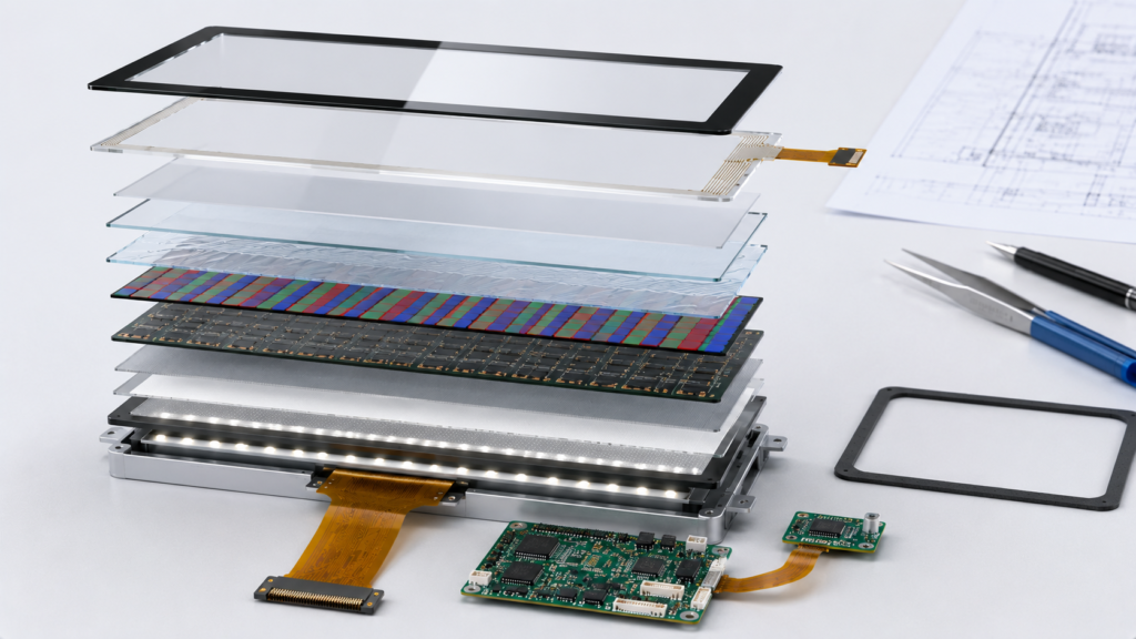
An LCD module, often called an LCM, is a display unit built around an LCD panel and the supporting components required to make it usable in an electronic product. The LCD panel itself controls how light passes through the pixel structure, while the module-level components help provide illumination, electrical connection, signal driving, and mechanical integration.
For simple embedded devices, an LCD module may be a compact display with a backlight, driver IC, and FPC cable. For more complex products, the LCD module may be combined with a touch panel, cover glass, optical bonding, controller board, custom firmware, or enclosure structure. This is why two LCD modules with the same screen size and resolution can behave very differently in real applications.
From an engineering perspective, the LCD module should be evaluated as a complete display system rather than only as a panel. The internal layers decide optical performance, while the external connection and mechanical structure decide whether the display can be integrated reliably into the final device.
Polarizers are thin optical films placed at the front and rear sides of the LCD cell. Their role is to control the direction of light waves. LCDs use the interaction between polarized light and liquid crystal orientation to create bright, dark, and intermediate grayscale states. Educational display references commonly describe LCD operation as using liquid crystals together with polarizers to control pixels.[2]
The rear polarizer receives light from the backlight side and aligns it before it enters the liquid crystal layer. The front polarizer filters the light after it has passed through the liquid crystal layer. Depending on the electrical state of the liquid crystal, more or less light can pass through the front polarizer, creating visible contrast.
Polarizers directly affect display readability. Their quality and matching with the LCD structure can influence contrast, viewing angle, brightness efficiency, and ambient-light performance. If a polarizer is scratched, delaminated, burned, or degraded by environmental exposure, the display may still power on but show poor contrast, uneven color, or visible surface defects.
For most LCD modules, polarizers are not treated as user-replaceable parts. If the polarizer is damaged, repair is usually not practical at the application level. For industrial or outdoor-facing products, polarizer durability should be considered together with cover glass, surface treatment, operating temperature, and UV exposure risk.
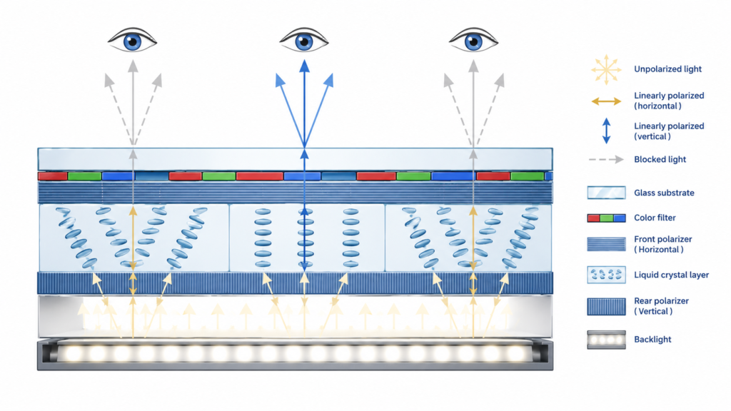
The LCD cell is built around two glass substrates. These glass layers provide the physical structure that holds the liquid crystal material in place and supports the precise pixel architecture. One substrate carries the TFT array, while the other carries the color filter structure in a typical TFT LCD design.
The spacing between the glass substrates must be controlled carefully because the liquid crystal layer thickness affects optical behavior. If the gap is uneven, the display may show non-uniform brightness, color variation, or mura. This is one reason why LCD manufacturing requires precise glass handling, alignment, and sealing.
The glass substrates also influence mechanical strength and product design. A bare LCD panel is fragile. It must be supported correctly during module assembly and final device integration. Excessive pressure, bending, enclosure stress, or incorrect mounting can damage the glass, create light leakage, or affect display uniformity.
When engineers design products around an LCD module, they should avoid placing pressure on the active display area. The mechanical structure should support the module through the recommended frame, bezel, or mounting area instead of forcing the panel glass to carry structural load.
The liquid crystal layer is the functional core of an LCD. It does not generate light by itself. Instead, it changes how polarized light passes through the panel. When voltage is applied, the orientation of liquid crystal molecules changes, which changes the amount of light transmitted through each pixel area.
This behavior allows the LCD to control brightness, grayscale, and contrast. In a TFT LCD, each subpixel can be controlled by electrical signals through the TFT array. The result is a full image formed by many individually controlled red, green, and blue subpixels.
The liquid crystal mode also influences viewing angle, response time, contrast, and color stability. TN, IPS, and VA LCD structures all use liquid crystals, but their molecular alignment and viewing behavior are different. This is why selecting an LCD module requires more than checking the diagonal size and resolution. The panel technology should match the application environment and user viewing position.
A color TFT LCD uses a color filter layer to convert controlled backlight into full-color images. Each pixel is typically divided into red, green, and blue subpixels. By adjusting the light transmission of these subpixels, the display produces different colors.
The color filter affects color saturation, color uniformity, transmittance, and overall visual quality. In a simple status display, color performance may not be the main selection factor. In a smart control panel, medical device interface, vehicle-related display, or user-facing HMI, color consistency can become more important.
The color filter also works together with the backlight spectrum. Even if the LCD panel has a good color filter, poor backlight selection can reduce color accuracy or produce inconsistent appearance across batches. For OEM projects, display color requirements should be discussed early if the product interface depends on accurate brand colors, warning indicators, or visual differentiation.
The TFT array is the active matrix control layer of a TFT LCD. It contains thin-film transistors that act as switching elements for individual subpixels. These switches allow the display to control each pixel area with greater precision than older passive matrix LCD technologies.
The TFT array is one of the reasons TFT LCD modules can support high-resolution images, fast screen updates, and stable grayscale control. It works with the driver IC to address rows and columns of pixels according to the image data provided by the host system.
For engineers, the TFT array itself is usually not a customizable item at the project level. However, the panel technology, resolution, viewing angle, brightness, interface, and driver configuration are all affected by the LCD panel design. A module that looks suitable mechanically may still fail to match the project if its interface, timing, or driver requirements are incompatible with the host system.
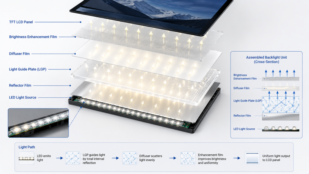
Because most LCDs do not emit light by themselves, they need a backlight unit. The backlight provides the illumination that passes through the LCD structure and becomes the visible image. DigiKey describes display backlights as components used to improve display visibility and readability.[3]
A typical LCD backlight unit may include LEDs, a light guide plate, diffuser films, reflector films, brightness enhancement films, and an FPC or connection structure. The purpose is to distribute light evenly across the display area. A poor backlight design can cause dark areas, bright spots, edge leakage, uneven color, or poor readability.
Backlight design affects brightness, power consumption, heat, thickness, lifetime, and outdoor readability. A high-brightness backlight can improve visibility in strong ambient light, but it may also increase power draw and thermal load. For sealed or compact equipment, heat management should be reviewed before increasing brightness.
For industrial, smart home, security, vehicle-related, or outdoor-facing devices, the backlight should be selected according to the real operating environment. The question is not simply how bright the display can be. The better question is whether the display remains readable under the expected lighting conditions without creating unacceptable power or thermal problems.
The driver IC is the component that controls how electrical signals are applied to the display panel. It translates image data and timing signals into the voltage patterns required by the TFT array and liquid crystal layer. Without the correct driver configuration, the LCD panel cannot display the intended image correctly.
The driver IC is closely connected to resolution, interface, refresh behavior, gamma characteristics, power sequencing, and display timing. In many compact LCD modules, the driver IC may be integrated directly on the glass or connected through the FPC structure. In larger or more complex display systems, additional controller boards may be required to convert signals such as HDMI, LVDS, MIPI, eDP, RGB, or other interfaces.
For product development, this is where many compatibility problems appear. The display may have the correct size and appearance, but the customer’s mainboard may not support the panel interface or timing. In these cases, a suitable controller board or firmware adaptation may be required.
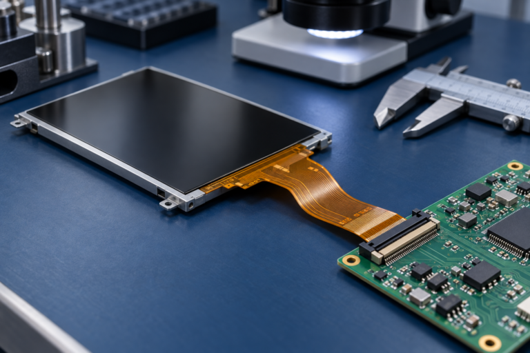
The FPC, or flexible printed circuit, connects the LCD module to the customer’s board or controller. It carries display signals, power, backlight lines, touch signals, or control signals depending on the module structure.
FPC design affects product integration more than many buyers expect. Its length, bending direction, connector position, pin definition, pitch, and reinforcement design can determine whether the display fits into the final housing. If the FPC exits in the wrong direction, the product may require mechanical redesign even when the display itself is correct.
Connectors also matter. A connector should match the customer’s PCB layout, assembly method, reliability expectations, and production process. In industrial or embedded equipment, cable routing should avoid sharp bends, moving parts, high-noise areas, and excessive mechanical tension.
When requesting a custom or replacement LCD module, buyers should provide the existing FPC drawing, pin definition, connector information, and mechanical constraints whenever possible. This helps reduce unnecessary sample revisions.
Many LCD modules are display-only. Others are integrated with touch panels and cover glass. The touch panel allows user input, while the cover glass protects the display surface and defines the front appearance of the product.
Projected capacitive touch, or PCAP, is widely used when the product requires a smooth glass surface, multi-touch operation, and modern interface behavior. Resistive touch remains useful in some applications that require pressure input, stylus use, glove operation, or certain rugged operating conditions.
Cover glass customization may include size, thickness, black border printing, logo area, hole design, edge treatment, and shape adjustment. It should be designed together with the enclosure and touch requirements. Thick cover glass, gloves, water, or electrical noise may require touch tuning, especially for PCAP touch systems.
For B2B projects, touch and cover glass should not be added at the end as cosmetic accessories. They should be considered during the display selection stage because they can affect brightness, touch sensitivity, optical clarity, mechanical fit, and final product assembly.
An LCD module works because its layers are coordinated. The backlight creates illumination. The rear polarizer aligns light. The liquid crystal layer modulates the light under electrical control. The color filter creates RGB subpixels. The TFT array controls individual subpixels. The front polarizer filters the modulated light to produce contrast. The driver IC and FPC provide the electrical control path. The optional touch panel and cover glass add interaction and protection.
If one part is poorly matched, the final module performance can suffer. A strong backlight cannot fully solve poor viewing angle. A good LCD panel can still fail if the FPC position does not fit the housing. A high-quality touch panel may behave poorly if the cover glass thickness or controller tuning is wrong. A display with the correct resolution may still be unusable if the interface is incompatible with the customer’s board.
| Component | Main Function | Engineering Impact |
|---|---|---|
| Polarizers | Control polarized light transmission | Affect contrast, viewing angle, and readability |
| Glass Substrates | Support LCD cell structure and pixel alignment | Affect mechanical stability and display uniformity |
| Liquid Crystal Layer | Modulate light under voltage control | Affect contrast, grayscale, response, and viewing behavior |
| Color Filter | Create red, green, and blue subpixels | Affect color performance and image quality |
| TFT Array | Control individual subpixels | Affect resolution, refresh behavior, and image precision |
| Backlight Unit | Provide illumination behind the LCD panel | Affect brightness, power consumption, heat, and readability |
| Driver IC | Convert image data into display control signals | Affect interface, timing, gamma, and display compatibility |
| FPC and Connector | Connect the module to the customer’s PCB or controller | Affect mechanical fit, pin definition, and integration reliability |
| Touch Panel | Enable user input | Affect user interaction, cover glass design, and controller tuning |
| Cover Glass | Protect the front surface and define appearance | Affect durability, sealing, optical clarity, and product design |
Before choosing an LCD module, engineers should confirm both display performance and integration details. The basic display parameters include size, resolution, active area, brightness, viewing angle, contrast, interface, operating temperature, and backlight requirements. These parameters decide whether the module can meet the visible and electrical requirements of the product.
Mechanical and integration details are just as important. Buyers should check outline dimensions, thickness, FPC position, connector type, mounting space, cover glass requirements, touch structure, bonding method, enclosure clearance, and cable routing. If the display must connect to a specific mainboard, the interface timing and driver requirements should be confirmed before sampling.
For custom projects, it is also important to define whether the customer needs a standard LCD module, a touch display module, a display with custom cover glass, a high-brightness backlight, FPC modification, controller board support, firmware adaptation, or a more complete display assembly. Clear requirements reduce the risk of selecting a module that looks correct but fails during product integration.
LCD module customization is usually most practical when it starts from an existing display module and modifies the surrounding structure. Common customization areas include brightness, backlight design, FPC, interface, touch panel, cover glass, controller board, firmware, and mechanical coordination.
Brightness customization may help when the display is used in high ambient light. Backlight customization may support different power or visibility requirements. FPC customization may help the display fit into a compact enclosure. Cover glass customization can support product appearance, front-panel protection, and touch integration. Controller board support can help connect the LCD module to HDMI, LVDS, MIPI, eDP, USB, or other system interfaces depending on the project.
Not every LCD component can be freely changed without cost or risk. For example, changing the active display size from scratch is very different from modifying cover glass or backlight around an existing module. Buyers should discuss customization goals early so that the supplier can recommend a feasible structure and development path.
RJY Display provides TFT LCD products, controller boards, and customization support for B2B display projects. For product teams that need LCD module selection or customization, RJY Display can help review the display size, resolution, interface, brightness, viewing angle, touch requirement, FPC design, backlight requirement, controller board compatibility, and mechanical structure.
If your project requires a standard TFT LCD module, a touch LCD module, a custom cover glass display, a high-brightness display, a display with controller board support, or customization based on an existing LCD module, contact RJY Display with your project details. Useful information includes display size, resolution, interface, brightness, touch type, operating environment, enclosure structure, annual demand, sample requirement, and any reference model or datasheet.
An LCD module is typically composed of polarizers, glass substrates, a liquid crystal layer, a color filter, a TFT array, a backlight unit, driver ICs, an FPC cable, connectors, and optional touch panel or cover glass.
No single part works alone. The liquid crystal layer, TFT array, backlight, driver IC, and polarizers are all essential for image generation, while FPC, touch panel, and cover glass affect integration and usability.
Most LCDs do not emit light by themselves. The backlight provides illumination behind the LCD panel so that the image can be seen.
The TFT array controls individual subpixels through thin-film transistors. This allows the display to show high-resolution images with precise pixel-level control.
Yes. A touch panel is optional. Some products use display-only LCD modules, while others require PCAP or resistive touch depending on the user interface and application environment.
Common customization areas include brightness, backlight, FPC, interface, touch panel, cover glass, controller board, firmware, and mechanical structure. The feasibility depends on the existing module and project requirements.
Share your display size, resolution, interface, brightness, touch requirement, controller board requirement, and application environment.
Continue reading related display technology guides and application references.
Explore product pages related to this article topic.
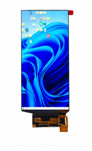
Talk to RJY’s engineering team for display matching, controller board review, and customization discussion.









