An embedded display module is a display assembly intended to be integrated into a product and driven by that product’s electronics. Embedded modules can use technologies such as TFT LCD, OLED or electronic paper. This guide focuses on TFT LCD integration, while explaining the system questions that apply to other display types.
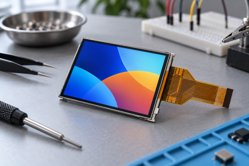
The term can describe a compact TFT LCD with a flexible cable and backlight, or a more complete assembly that adds touch sensing and controller electronics. The supplier’s definition determines what is actually included.
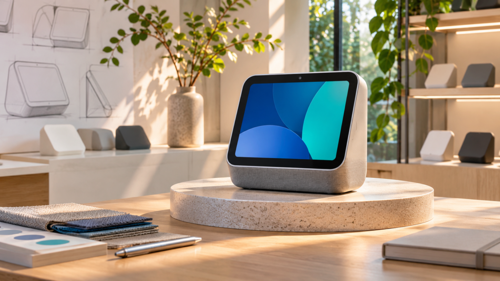
For an OEM, selecting the module is a system decision. The image path, power, backlight, touch, firmware, mechanical fit and operating environment must work together. A module with the right diagonal size is not necessarily compatible with the host or suitable for the enclosure.
What is included in an embedded display module?
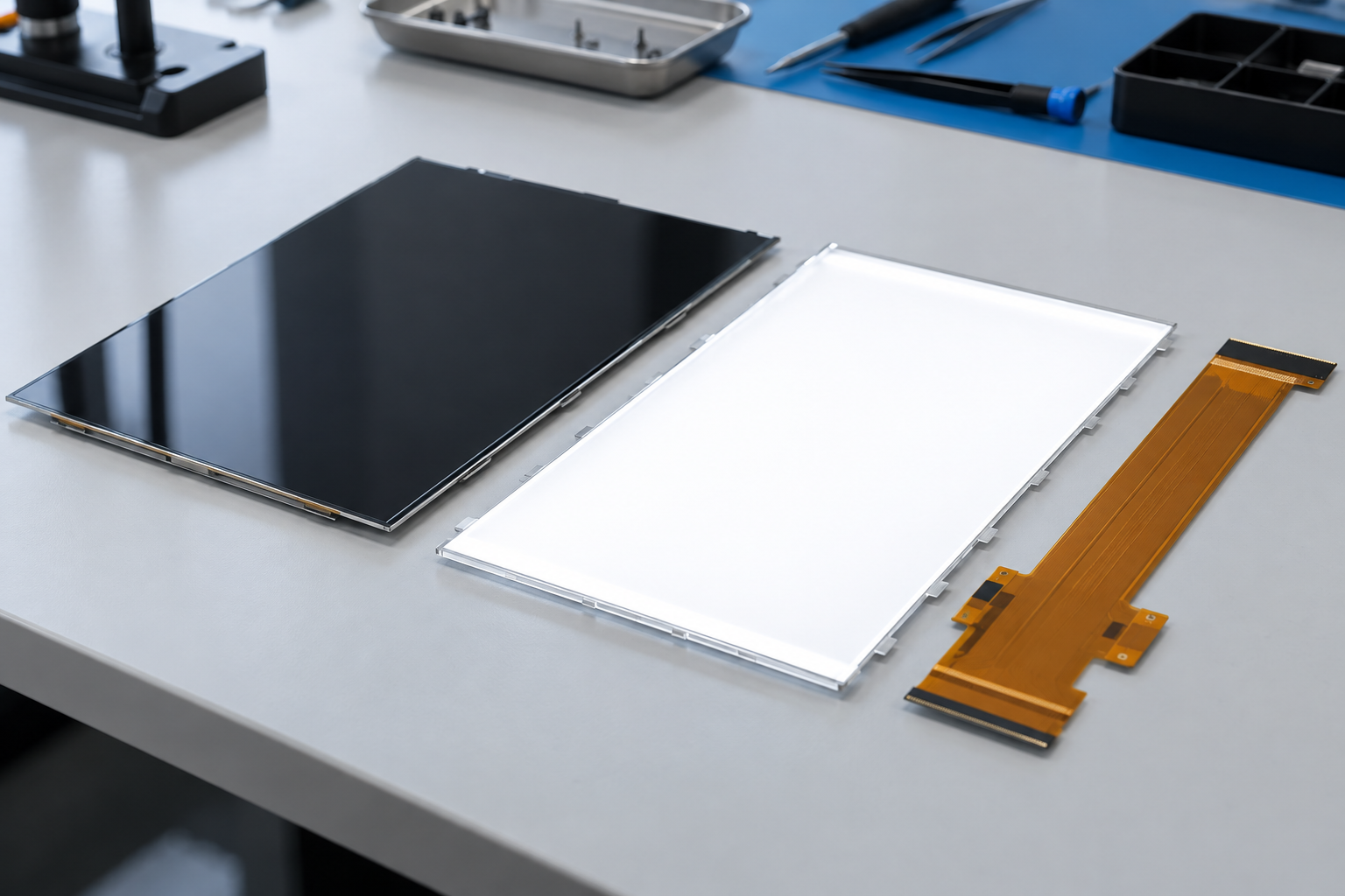
A typical transmissive TFT LCD module combines an LCD panel with supporting parts. The panel controls light through a liquid-crystal layer; a backlight provides illumination. Depending on the module, driver ICs, a flexible printed circuit (FPC), mechanical frame, touch sensor or cover glass may also be included. These are common components, not a fixed bill of materials.
When comparing offers, distinguish the panel, the module and a complete display assembly. A panel may mean the display glass and associated drivers. A module may add a backlight and connections. A complete assembly can add touch, cover glass, controller boards and an enclosure. Confirm the drawings and included parts for the exact model.
Different display technologies use different optical architectures. A transmissive TFT LCD controls light from a backlight; an OLED emits light at the display elements; electronic-paper modules generally use reflected light. Their update behavior, power profile and controller requirements depend on the individual module, so a technology label alone is not a complete specification.
| Element | Function | What to confirm |
|---|---|---|
| LCD panel and drivers | Form and control the image. | Active area, resolution, timing, interface and driver requirements. |
| Backlight | Illuminates a transmissive LCD. | Electrical drive, dimming, luminance and thermal conditions. |
| FPC and connector | Connect the module to the rest of the system. | Pin assignment, pitch, orientation, routing and mechanical support. |
| Touch system | Reports user input when included. | Sensor, controller, interface, firmware and environmental behavior. |
| Controller or host | Supplies display data, power and control. | Supported signal, timing, software and power sequence. |
How does the module connect to an embedded host?
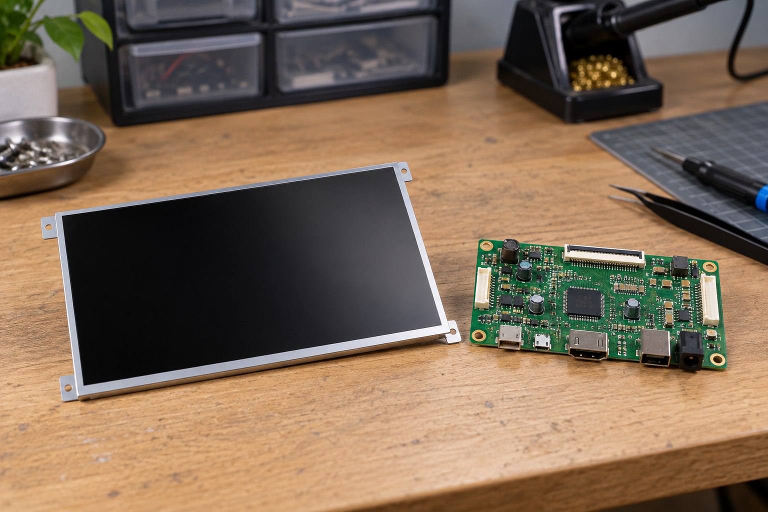
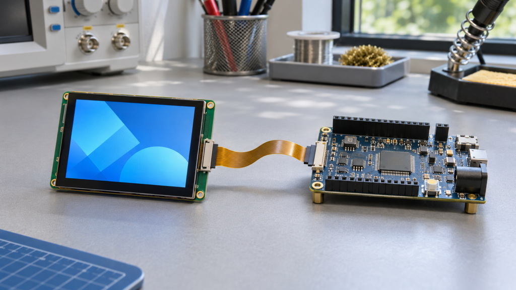
The host generates an image using an application, graphics library or operating system. A display controller then sends data in the format required by the module. Some modules include a display controller and graphics memory; others rely on the host to provide a continuous stream of image data. STMicroelectronics describes both approaches in its LCD-TFT controller application note.[1]
The architecture matters before a board is selected. A compact microcontroller interface may transfer changed regions to a module with its own graphics memory. A different module may require the host to scan a framebuffer continuously. The actual module datasheet and host controller determine the permitted behavior.
Display and touch are separate paths
The display interface carries image data and control signals. A touch controller commonly reports input through another connection, such as I²C, SPI or USB, depending on the design. It may also require its own power, reset, interrupt and driver configuration. An image on screen does not prove that the touch path is configured.
A display module may use a flexible circuit for both functions. A shared connector does not make the signals interchangeable. Verify the pinout against the exact panel and touch-controller documentation.
Common display interfaces and their boundaries
| Interface | Useful question for the design | Additional checks |
|---|---|---|
| SPI or MCU-style interface | Does the module have its own display controller and memory, and can the host update the required content fast enough? | Command set, pixel format, transfer rate and initialization. |
| Parallel RGB | Can the host generate the required pixel data and timing continuously? | Bus width, clock, sync or data-enable mode and signal voltage. |
| LVDS | Do the host and panel support the same link and data mapping? | Channel configuration, mapping, timing, connector and power. |
| MIPI DSI | Does the host support the panel’s DSI configuration? | Lane count, mode, initialization, timing and firmware. |
| eDP | Can the host and panel establish a supported link and display mode? | Link capabilities, connector, panel power and software support. |
| HDMI | Is HDMI an input to a complete controller assembly, or is the module itself an HDMI device? | Controller-board output, panel match and touch path. |
These interface names describe families, not interchangeable pinouts. Two panels with the same interface name and resolution can require different timing, initialization, mapping or power. A MIPI DSI integration can also require panel-specific reset, power, link configuration and initialization.[4] An HDMI source cannot be assumed to connect directly to a bare MIPI panel. Such a project may need an active bridge or controller and panel-specific configuration.
Choose the image and viewing requirements first
Define the content, viewing distance and orientation before selecting a pixel matrix. A panel for large status indicators has different needs from one showing dense text or camera images. Resolution determines the number of image pixels; active-area dimensions determine their physical size. Check that critical text and touch targets remain usable at the intended viewing position.
Aspect ratio and shape also matter. A narrow bar or round module may fit a product enclosure but require a custom interface layout. Confirm the visible active area, not only the module outline. Test representative screens with long labels, alarms and any required localization.
Specify luminance under the conditions that matter to the user. Cover glass, bonding, reflections and viewing direction can change the finished assembly’s appearance. A nominal brightness value alone does not prove sunlight readability. Evaluate representative content under the intended ambient light and after the specified operating period.[3]
Check electrical and software compatibility
Begin with the exact panel model and datasheet. Compare its interface, pin definition, supply voltage, power sequence, reset and initialization requirements with the host. Where applicable, check timing, pixel format, lane or channel configuration and any driver IC requirements. Similar connector size or pin count is not evidence of the same electrical assignment.
For a controller-board match, collect the panel model, resolution, interface, pinout, timing and driver IC when available, along with backlight and touch requirements. The operating system, firmware and intended use also matter. RJY can discuss adaptation across common host and panel interfaces as a project-dependent review; it is not a promise that any board will drive any panel.
Framebuffers and update performance
A framebuffer stores image data. Its capacity depends on the pixel dimensions, storage format, row stride and number of buffers or layers. A first estimate for a tightly packed buffer is width × height × bytes per pixel; a real allocation may include row padding and other memory. Use the actual stride and allocation rules.
Memory capacity and memory bandwidth are different. A system can have enough memory to hold a frame yet fail to read and update it at the required rate when other processors or peripherals share the bus. Test the real interface, software workload and update behavior rather than choosing a processor on resolution alone.
Specify the backlight and touch system separately
The backlight has its own electrical requirements. Confirm whether the module includes a driver, the required voltage and current conditions, and the supported dimming method. Higher output can increase power and heat; the result at the finished viewing surface depends on the complete optical stack.
Touch is optional. Projected capacitive and resistive sensors use different sensing methods, and each has design-specific limits. If gloves, moisture or a stylus are required, state the exact input and test conditions. Cover material and thickness, bonding, grounding, electrical noise and controller tuning can affect the result.[2] A touch-panel label does not establish support for a particular glove or number of contacts.
Make the mechanical design part of selection
Compare the active-area position, overall outline, thickness and mounting features with the enclosure drawing. Include tolerances for the module, cover, adhesive and housing. Check that the bezel does not press unevenly on the active display area or interfere with touch near the edges.
The FPC needs space for its connector and bend. Confirm the allowed routing, bend radius and direction from the actual drawing. Protect the connection from repeated movement or mechanical load where the product design requires it. A module that fits a two-dimensional opening can still fail to fit once the connector and cable path are included.
Validate the complete assembly

Build the first evaluation around the configuration that will be released: panel revision, host board, firmware, touch controller, cover, backlight driver and enclosure. Use the module datasheet as the source for electrical limits and startup or shutdown sequencing.
- Check supplies, reset and initialization against the documented module requirements.
- Verify native image timing, orientation, color, startup, sleep, wake and repeated restart.
- Exercise the representative UI at the required viewing distance and ambient light.
- Check touch coordinates, edge targets, gestures and required input tools with the final cover and enclosure.
- Evaluate backlight dimming, power and temperature in the intended operating mode.
- Record failures and the exact hardware and software revisions tested.
A blank or white display is a symptom, not a single diagnosis. Check the backlight, logic supplies, initialization, interface and timing as separate parts of the system. A touch failure can likewise arise in the sensor, controller, cable, driver or coordinate mapping. Use measurements and the specific documentation to narrow the cause.
When is customization useful?
An existing module can provide a starting point when its panel fits the image and interface requirements. Depending on the project, a supplier may be able to review changes around it, such as a touch sensor, cover glass, backlight, FPC or controller-board configuration. Feasibility depends on the selected module and the required volumes and process; it should not be assumed for every panel.
Discuss the boundary of the requested supply: bare display module, touch assembly, controller-board display or a larger integrated system. The decision affects the drawings, firmware, tests and responsibilities needed for the project.
Frequently asked questions
Is an embedded display module the same as a monitor?
Not necessarily. A module is usually a component intended for integration, while a monitor may include a housing, video input, power supply and controls. Confirm what the supplier includes.
Can any host board drive an embedded LCD module?
No. The panel, interface, pinout, timing, power, backlight, touch and software must be matched and tested for the specific configuration.
Does a touch LCD use the same connection for image and touch?
Not always. Image data and touch events commonly use separate electrical paths, even when they share a module or connector.
Does high brightness guarantee outdoor readability?
No. Ambient light, reflection, viewing angle, optical layers, content and sustained operating conditions also affect readability.
Prepare an embedded display project for review
Share the intended use, active-area constraints, resolution, viewing conditions, host platform, available display interface, touch needs, power and mechanical requirements. If a panel is already selected, include its model and datasheet. This lets the supplier assess the complete connection rather than guessing from screen size.
Explore RJY display modules or contact RJY Display for a project-specific review.