Facing a bottleneck in your Embedded Display Project?
Don’t let complex integration or supply chain issues slow your time-to-market. Book a free consultation with the RJY expert team for tailored design and manufacturing support.

An access control terminal display has a focused but demanding job. It must give users immediate, unambiguous feedback while sharing a compact front panel with a camera, credential reader, illumination system, microphone, speaker, keypad, fingerprint sensor or other authentication hardware.
The TFT LCD is therefore only one part of the terminal. It does not verify a credential, make an access decision or directly control the door merely because it shows an approval or rejection message. Those functions belong to the terminal software, credential subsystem, door controller and wider access-control architecture.
For OEM teams, the correct design process starts by defining the complete user interaction and system boundary. Display size, aspect ratio, interface and touch technology can then be selected against that architecture rather than treated as independent catalog choices.
“Access control terminal” can describe several different products. A simple reader may only need a compact status display. A time-and-attendance terminal may require employee information, schedule prompts and touch navigation. A visitor terminal may include a camera, QR-code workflow, intercom and larger graphical interface. A biometric terminal may need to coordinate face positioning, credential prompts, enrollment and transaction feedback.
The first engineering step is to document which functions are local to the terminal and which are performed elsewhere.
| Terminal role | Typical display requirement | System questions |
|---|---|---|
| Status reader | Short prompts, credential status, door state and fault messages | Does the reader make a local decision or report to a separate controller? |
| Touchscreen access terminal | PIN entry, menu navigation, visitor prompts and contextual instructions | Which actions are allowed locally, and how are touch events secured and validated? |
| Biometric terminal | Positioning guidance, progress feedback, retry instructions and result states | Where are biometric capture, matching, templates and privacy controls handled? |
| Time-and-attendance terminal | User identity, clock-in or clock-out state, work codes and transaction confirmation | What must remain available when the network or server is offline? |
| Visitor or intercom terminal | Directory, call state, camera preview, instructions and accessibility support | How are video, audio, touch, door release and remote operator functions separated? |
A requirement such as “4-inch Android access display” is not yet sufficient. The engineering baseline should also define the user journey, authentication methods, door-controller architecture, network dependencies, installation environment, viewing position, power source, enclosure, software ownership and production quantities.
Access control terminals are usually space-constrained because the front surface must accommodate more than a screen. A camera may need to remain near eye level. An RFID antenna must avoid materials and electronics that interfere with its intended operation. A fingerprint sensor needs an accessible physical position. Speakers, microphones and illumination components require openings or controlled optical paths.
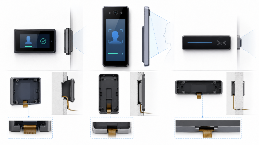
The display format should follow this layout.
A small landscape TFT LCD can work well when the terminal primarily shows status, short instructions, icons or a simple PIN interface. Its width can support text and side-by-side visual elements, but it may compete with the reader or camera for horizontal front-panel space.
A portrait display can support vertically ordered steps such as present credential, enter PIN, position face, wait and view result. This format may align naturally with a narrow wall-mounted terminal. The team must still verify touch-target size, one-handed operation, text length and camera placement.
A narrow bar LCD may be useful when the product requires a slim status area above or beside a credential reader. It can provide a distinctive industrial design and preserve space for cameras or sensors. However, a stretched aspect ratio limits conventional UI layouts, so the application must be designed specifically for the active area.
RJY Display’s public Smart Access demonstration used a small bar-type LCD with an Android motherboard, showing that this architecture can be considered for a defined access-terminal project. The demonstration should not be interpreted as proof that every bar display or Android board is automatically suitable for every access-control system.
A door terminal interaction is brief. Users do not expect to study a complex interface while standing at an entrance. The display should make the current state clear without relying on a single color, small icon or short-lived animation.
At minimum, define the visual behavior for:
Success and failure states should remain visible long enough to be understood, but the screen should return to a privacy-preserving idle state without exposing information about the previous user.
Although an embedded terminal interface is not automatically a web page, WCAG 2.2 provides useful UI design references. It specifies a contrast ratio of at least 4.5:1 for normal text and 3:1 for large text under its minimum-contrast criterion. It also defines minimum and enhanced pointer-target guidance for interfaces operated by touch.1
These values do not replace the product’s applicable accessibility requirements or real-device testing. They provide a starting point for evaluating text, icons and controls. Final readability still depends on pixel density, font rendering, cover-glass reflections, viewing distance, installation height, ambient light and the eyesight of real users.
Avoid using color alone to distinguish granted and denied states. Combine color with a clear icon, text, audio or another appropriate signal. The UI should also avoid presenting a green confirmation while the door controller reports a conflicting state.
The display is an output device. The touch sensor, camera, RFID reader, fingerprint sensor, keypad and microphone are separate input systems. They may share a host processor and enclosure, but they have different interfaces, drivers, timing requirements and failure modes.
| Subsystem | Primary function | Typical integration questions |
|---|---|---|
| TFT LCD | Shows prompts, status and graphical UI | Panel interface, timing, power, backlight, viewing angle and mechanical fit |
| Touch sensor | Reports user touch coordinates or gestures | Touch controller, USB or I2C path, cover stack, tuning, grounding and driver |
| Camera and illumination | Captures images for approved application functions | Field of view, image interface, lighting, thermal load, privacy and application ownership |
| Credential reader | Reads a card, tag, mobile credential or other supported token | Antenna position, protocol, controller boundary, electrical noise and enclosure materials |
| Fingerprint or keypad input | Provides another authentication factor or user input method | Physical access, data path, cleaning, wear, privacy and local software integration |
| Microphone and speaker | Provides intercom or audible feedback | Audio codec, acoustic design, echo, openings, sealing and application behavior |
A failure in one subsystem should not be disguised by another. For example, a functioning LCD does not prove that the credential reader is online. A camera preview does not prove that biometric processing or the door controller is available. A touch animation does not prove that the requested operation has been accepted.
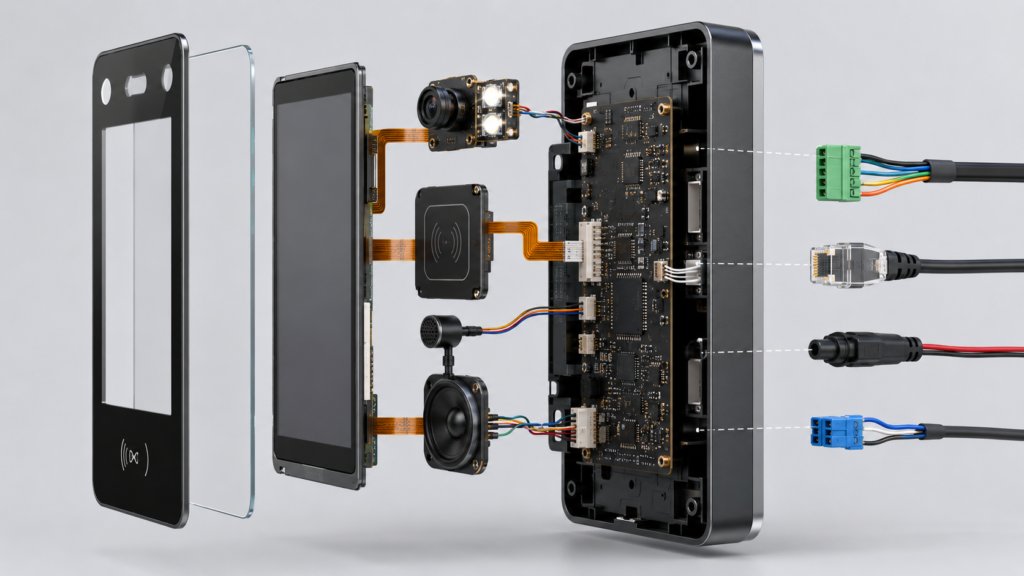
The display path depends on the selected host board. Compact embedded systems may use RGB, MIPI DSI, LVDS, eDP, SPI or another supported panel interface. A controller-board display may instead accept an external video source such as HDMI.
These architectures must not be mixed casually. HDMI cannot passively drive a raw MIPI, RGB, LVDS or eDP panel. An active receiver, bridge, scaler or controller board is required to translate the source video into the electrical format, timing and initialization expected by the LCD.
Touch remains a separate input path. In a typical HDMI touch display, HDMI carries the image and USB carries touch coordinates. An embedded touch controller may instead connect through I2C or another interface. The USB Implementers Forum publishes the Human Interface Device class specifications used by compliant USB input devices.2
Before selecting the module, confirm:
An access terminal may contain an Android or Linux computing board that drives the display, touch UI, camera, audio and network application. The same enclosure may also contain door-control electronics, or the terminal may communicate with a separate secure controller.
The project must define which component makes the access decision and which component energizes the lock. A graphical application should not be assumed to be the sole security boundary simply because it runs on the screen’s host board.
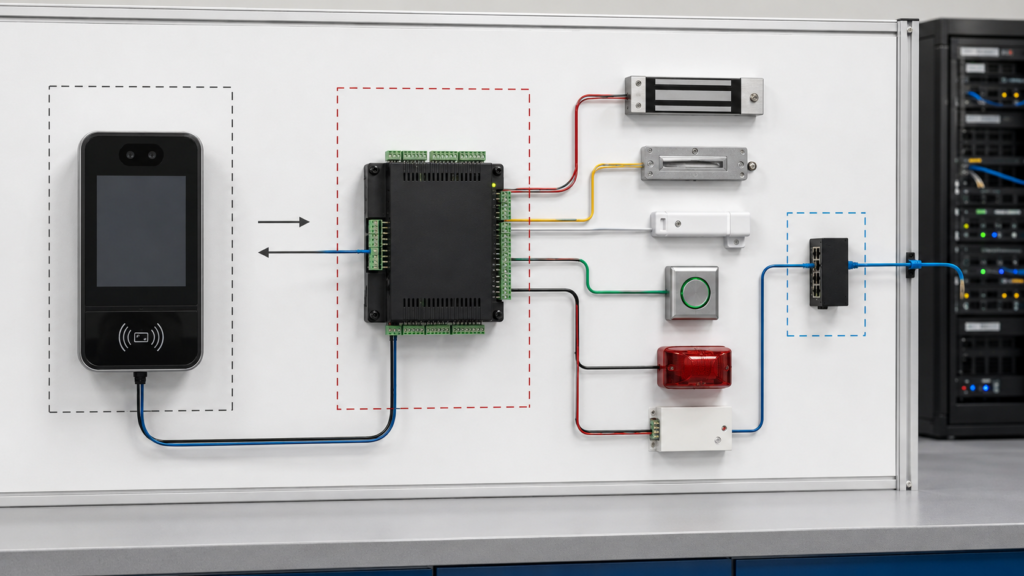
The Security Industry Association describes the Open Supervised Device Protocol as an access-control communications standard intended to improve interoperability among access-control and security products. The current SIA information identifies OSDP v2.2.2 and notes that OSDP has been published as IEC 60839-11-5.3
This does not mean every RJY Display board or proposed terminal supports OSDP. If a project requires OSDP, RS-485, Wiegand, Ethernet, CAN, relay I/O or another communication method, the exact hardware, electrical design, software implementation and certification requirements must be confirmed for that project.
Network loss, server unavailability and door-controller communication loss are different events. The UI should present only the state that the terminal can verify.
Questions to resolve include:
A generic “offline” icon is insufficient if different offline states require different service actions or access policies.
An Android board can provide graphics, networking, camera, audio and application support, but “Android-compatible LCD” is not a complete engineering specification. Compatibility must be established for the exact panel, board revision, bootloader, kernel, BSP, device tree, display driver, touch driver and application image.
The system team should confirm whether each peripheral uses a supported native interface or requires an external bridge or controller. Available connectors do not by themselves prove that every camera, display, touch sensor, credential reader or audio device can operate simultaneously.
Software responsibilities should also be assigned before prototype approval:
RJY Display supports controller-board and firmware discussions for defined display projects, but software adaptation is project-dependent. It should not be treated as an automatic plug-and-play capability.
The terminal front panel must be designed as one mechanical and optical assembly. The LCD active area, touch sensor, camera windows, illumination openings, reader antenna, microphone, speaker, fingerprint sensor, printed border and mounting features all compete for controlled space.
Review the complete drawings for:
Cover glass can be coordinated around an existing display platform, but it does not independently establish impact, ingress or environmental certification for the finished terminal. Those properties depend on the complete enclosure, materials, seals, mounting and qualification program.
A display sample that shows a test image is not yet a validated terminal. The representative prototype should include the intended LCD, touch stack, host board, camera, illumination, credential reader, audio hardware, door-controller interface, power architecture, cable routing, enclosure and software release.
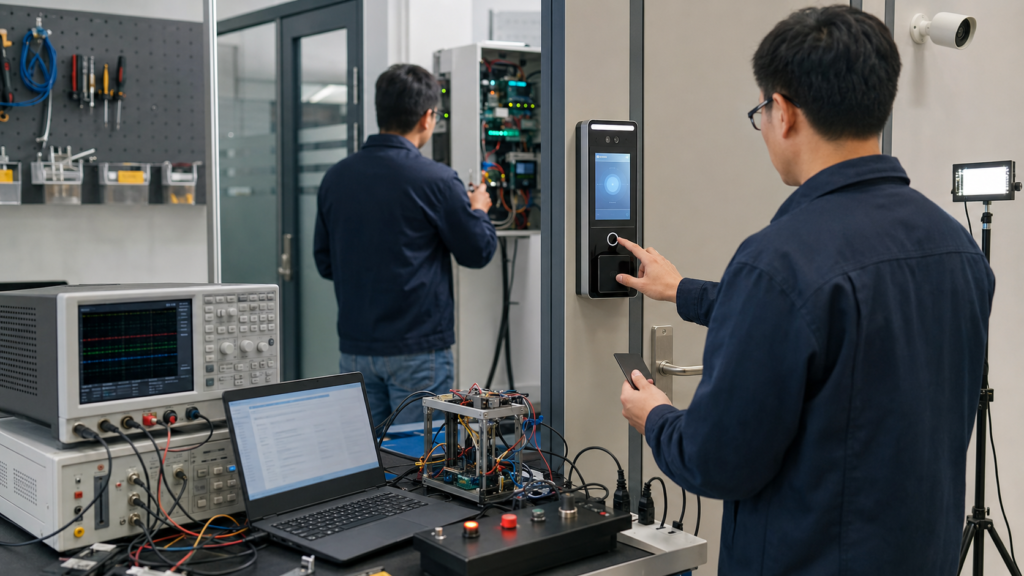
Check every user state from the intended mounting height, viewing distance and approach direction. Test normal and low ambient light, reflections, language variants, long names, error text, screen rotation, dimming, wake-up and privacy timeout.
Verify touch accuracy, edge behavior, reader operation, camera alignment, illumination, fingerprint or keypad access, audio level and microphone performance in the assembled enclosure. Exercise the peripherals together rather than only one at a time.
Test cold start, repeated power cycles, application restart, watchdog recovery, network disconnection, server reconnection, door-controller communication loss, peripheral disconnection where safe, failed software update and rollback. Confirm that the screen never presents an access-granted state without the corresponding approved system event.
The approved configuration should identify the LCD model and revision, touch sensor, cover-glass drawing, camera, reader, audio components, host-board revision, door-interface hardware, cable drawings, firmware, BSP, device tree, application build, configuration files and production test procedure.
A working engineering sample is not reproducible if it depends on an undocumented cable, manually installed driver, temporary register setting or unrecorded touch configuration.
For a useful engineering review, provide:
RJY Display can review available TFT LCD modules, bar displays, touch options, controller boards and customization around an existing display platform. The discussion can include cover glass, backlight, FPC, interface, touch, controller board, firmware and mechanical coordination according to project feasibility.
A compact landscape, portrait or bar-type TFT LCD may be suitable depending on the terminal’s UI, camera, credential reader, keypad, fingerprint sensor and enclosure layout. The correct format should be selected from the complete front-panel architecture rather than display size alone.
No. The TFT LCD displays prompts and results. Camera capture, biometric processing, credential reading, access decisions and door control belong to separate hardware and software functions, even when several functions share one embedded host board.
No. HDMI requires an active receiver, bridge, scaler or controller board to generate the panel-compatible interface, timing and initialization. A passive cable cannot perform that conversion or provide the panel power and backlight functions.
No. Compatibility must be verified for the exact LCD, touch controller, board revision, interface, timing, connector, power, bootloader, kernel, BSP, device tree and software image. Peripheral requirements such as cameras, readers, audio and door-controller communication must also be checked.
Test the complete display and touch stack, camera and illumination, credential reader, audio, door-controller communication, UI states, viewing conditions, startup, repeated power cycles, network loss, controller loss, application recovery, software update behavior, enclosure assembly and the controlled production configuration.
Share your display size, resolution, interface, brightness, touch requirement, controller board requirement, and application environment.
Continue reading related display technology guides and application references.
Talk to RJY’s engineering team for display matching, controller board review, and customization discussion.