Facing a bottleneck in your Embedded Display Project?
Don’t let complex integration or supply chain issues slow your time-to-market. Book a free consultation with the RJY expert team for tailored design and manufacturing support.

An EV charging station display is not simply a screen placed inside a charger enclosure. It is the visible part of a larger human-machine interface that may need to present connection instructions, authentication steps, charging status, energy information, payment guidance, warnings, and recovery messages under changing environmental conditions.
For an equipment manufacturer, selecting the display therefore requires more than choosing a diagonal size and brightness figure. The engineering team must coordinate the TFT LCD, touch sensor, cover glass, optical stack, controller or host board, video interface, touch input, backlight power, enclosure, software, network state, and validation plan.
This guide explains how to define those requirements without confusing a raw LCD module with a controller-board display, an external monitor, or a complete EV charger HMI.
The correct display architecture depends first on where and how the charger will be used. An indoor residential wallbox, a covered commercial charger, and a public outdoor DC charging station do not present the same display problem.
Before selecting a module, document the installation environment, expected viewing position, user journey, operating schedule, enclosure design, local computing platform, network behavior, service strategy, and required information states. A display that performs well on an indoor engineering bench may become difficult to read, difficult to touch, or thermally unstable after it is installed behind a protective front surface in a sealed outdoor enclosure.
| Project condition | Display-system implication |
|---|---|
| Indoor or sheltered charger | Ambient light and weather exposure may be moderate, but viewing position, UI clarity, touch behavior, and lifecycle still require validation. |
| Outdoor public charger | Reflection, direct sunlight, rain, contamination, temperature, vandal exposure, sealing, and thermal load become system-level concerns. |
| Compact wallbox | Mechanical depth, FPC routing, power budget, touch integration, and simplified status presentation may control the design. |
| Large commercial charging terminal | The display may need more visual area, longer viewing distance, richer instructions, accessibility review, and coordination with payment or identification hardware. |
| Unattended operation | Startup recovery, visible error states, remote status synchronization, long screen-on periods, and service diagnostics require explicit testing. |
Resolution should follow the actual information architecture rather than a marketing preference for the highest available pixel count. Prepare representative screens for initial guidance, connector status, user authentication, charging progress, cost or energy information where applicable, completion, interruption, network loss, and service conditions.
Review the smallest text, icons, QR codes, progress indicators, language variants, and touch targets at the intended viewing distance. If several languages are required, confirm that longer translations still fit without reducing critical text to an impractical size.
For UI contrast, engineering teams can use established accessibility guidance as a design reference. WCAG 2.2, for example, specifies a minimum contrast ratio of 4.5:1 for normal text and 3:1 for large text under its Level AA criterion.1 An embedded charger interface is not automatically a web page, and applicable accessibility obligations vary by market, but the underlying contrast and target-size principles are still useful during UI validation.
Do not approve the display from a static design file alone. Render the interface on the actual LCD, behind the intended touch and cover stack, under realistic light. The final perceived contrast may differ substantially from the source artwork.
A high backlight output can help in bright ambient conditions, but brightness alone does not determine outdoor readability. The user sees the combined result of the LCD cell, backlight, polarizers, touch sensor, bonding layer or air gap, cover glass, surface treatment, enclosure angle, ambient reflections, UI colors, and thermal behavior.
Increasing backlight power without reviewing the rest of the stack may raise electrical consumption and internal temperature while leaving strong front-surface reflections unresolved. RJY Display’s existing TFT LCD structure guidance similarly notes that backlight design affects brightness, power consumption, heat, thickness, lifetime, and outdoor readability.
The display review should identify every optical and mechanical layer between the backlight and the user:
Optical bonding can reduce internal reflecting interfaces and improve the mechanical unity of the stack, but it is not a substitute for validating the full assembly. Material compatibility, bonding process, touch behavior, rework strategy, thermal expansion, appearance and environmental tests must be defined for the actual construction.
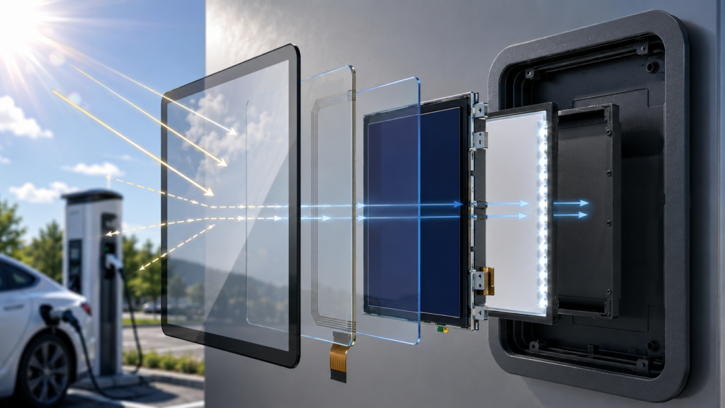
Surface treatments should also be evaluated as a tradeoff. A treatment intended to reduce distracting reflections may affect apparent sharpness, haze, color, cleaning behavior or cosmetic acceptance. Sample evaluation under the real viewing geometry is more reliable than selecting from a generic treatment name.
An interface optimized only for daylight can become uncomfortable at night, while a low-output night setting may be unreadable in direct sun. Define brightness-control states, transition behavior and the source of any ambient-light decision. Confirm what happens if a sensor fails or reports an implausible value.
Brightness control is normally a function of the backlight driver, controller board and software. It should not be assumed to exist merely because the selected panel has an LED backlight.
The touchscreen and LCD serve different functions. The LCD receives image data; the touch controller reports user input to the host. A charger can display a correct image while its touch input is unavailable, offset, noisy or incorrectly mapped.
Projected-capacitive touch is common in modern graphical interfaces, but outdoor behavior depends on the complete sensor design, controller selection, cover construction, grounding, tuning, firmware and enclosure. Water droplets, wet fingers, gloves, contaminants, charger power electronics and cable routing can all change the sensing environment.
Some touch-controller families use both mutual- and self-capacitance measurements to improve touch classification and robustness.2 This is evidence that touch performance depends on controller technology and configuration; it is not evidence that every capacitive touch assembly will automatically support rain or gloves.
The requirement should state whether the user may operate the charger with a bare dry finger, wet finger, work glove or other expected input. It should also define acceptable behavior when water is present: continuing to detect an intentional touch, rejecting false input, or temporarily disabling touch while preserving a safe alternative interaction.
Touch testing should cover:
Depending on the architecture, touch data may use USB, I2C or another supported path. USB touch may be implemented through the Human Interface Device class, but host compatibility still depends on the touch controller, descriptors, operating system, drivers and application behavior. The USB-IF publishes the HID class definition used by compliant USB input devices.3
An LCD described as “HDMI touch” normally uses HDMI for video and a separate USB connection for touch. HDMI itself does not carry the touchscreen coordinates to the host in that arrangement.
A clear delivery boundary prevents major integration errors. The terms display, touch display, monitor and HMI are often used interchangeably in early discussions even though they represent different assemblies.
| Delivery level | Typical contents | Work remaining for the charger manufacturer |
|---|---|---|
| Raw or integrated TFT LCD module | LCD, driver IC, FPC and backlight; touch may or may not be included | Panel timing, power, backlight, interface, touch, cable, host software and mechanical integration |
| LCD plus controller board | Display with an active board that accepts a defined host input and drives the panel | Power, touch path, software, cables, enclosure, thermal design and production configuration |
| External touch monitor | Display electronics, enclosure and external video input; touch usually uses a separate data path | Host computer, application, charger integration, environmental protection and system validation |
| Embedded HMI subsystem | Display, touch, computing board, software image and mechanical assembly to an agreed boundary | Charging-control integration, backend communication, safety architecture, final enclosure and complete product qualification |
RJY Display supplies TFT LCD modules and controller-board options that can be discussed separately or as part of a defined display solution. The project team should agree in writing which party owns the panel configuration, touch driver, backlight behavior, startup sequence, application image, enclosure and production test.
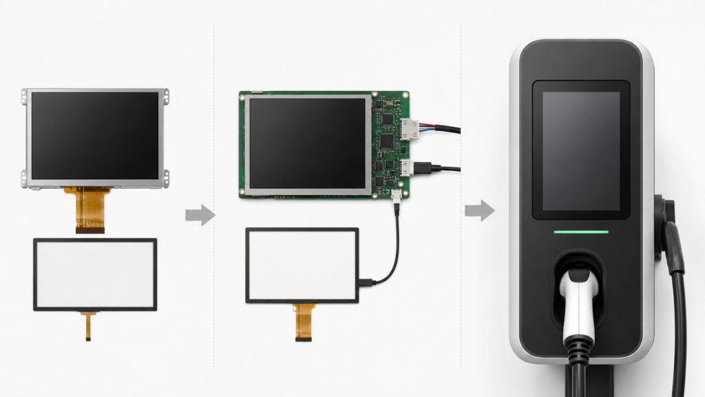
A raw TFT LCD may use MIPI DSI, RGB, LVDS, eDP or another panel interface. An application processor may provide one of these interfaces natively, while another system may need an active bridge, scaler or controller board.
HDMI is normally an external video interface. It cannot be converted into the timing, mapping, power and initialization required by a raw MIPI, RGB, LVDS or eDP panel through a passive cable. An active receiver or controller must accept the HDMI signal and generate the panel-compatible output.
Before selecting the display path, confirm:
If an Android controller board is being considered, compatibility must be established for the exact LCD, board revision and software image. “Android display” is not a panel interface, and an Android board does not automatically support every LCD of the same resolution.
The Open Charge Alliance defines OCPP as the communication protocol between charging stations and charging management systems.4 The local TFT LCD does not itself become OCPP-compatible.
A typical system may contain several separate software and hardware domains:
The HMI application may receive charger status from another controller and present it to the user. Alternatively, the same computing platform may perform several roles. In either case, the interface contract must define the source, timing and validity of each displayed state.
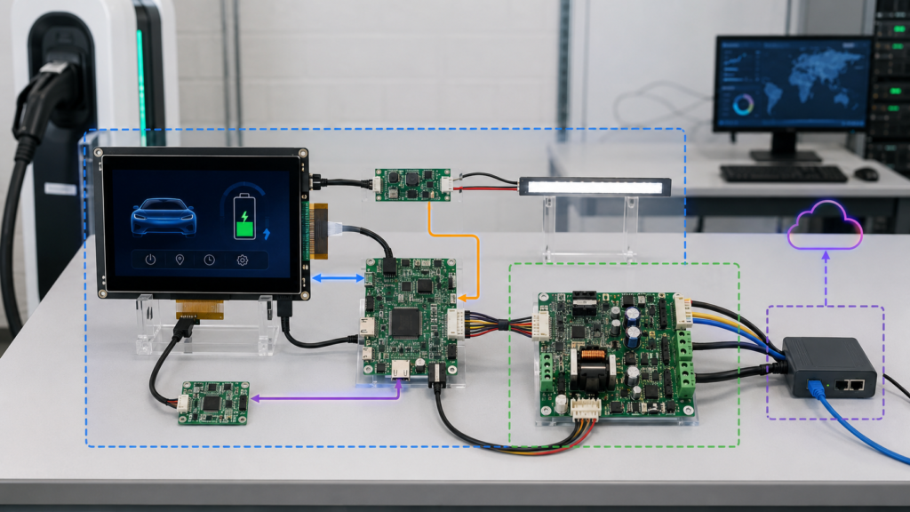
Network loss should not produce a frozen or misleading screen. The UI should distinguish between a display failure, an unavailable backend service, an interrupted transaction, a connector problem and a charger fault according to the product’s approved behavior.
Outdoor charging equipment may combine solar loading, charger heat, display backlight heat, computing-board heat and a sealed enclosure. The temperature at the LCD, polarizer, bonding material and touch controller may differ from ambient temperature.
A higher-output backlight can improve luminance while also increasing power consumption and local thermal load. The enclosure designer should model and measure the assembled system rather than assuming that a panel’s ambient operating range represents the temperature of every component inside the charger.
Thermal validation should include the intended brightness policy, processor workload, charging state, solar exposure, enclosure color and material, ventilation or conduction path, and worst-case installation orientation. The test should also observe image uniformity, color behavior, touch response, backlight control, restart and recovery.
The display drawing should be reviewed together with the enclosure drawing before tooling. Important dimensions include the LCD outline, active area, viewing area, touch-sensor outline, cover-glass shape, printed border, FPC exit, connector location, cable bend, component height, mounting features and required keep-out regions.
The bezel must not hide active information or create excessive shadow at the intended viewing angle. It must also avoid mechanically loading the LCD, touch sensor or bonded stack in an uncontrolled manner.
Environmental protection belongs to the complete charger enclosure and front-panel construction. A protective cover glass alone does not establish an ingress-protection rating for the finished equipment. Seals, joints, cable entries, fasteners, drainage, materials and assembly processes must be evaluated at product level.
A desktop image test is not enough for an outdoor EV charging HMI. The prototype should represent the intended LCD, touch sensor, cover glass, bonding construction, controller board, cable, grounding, enclosure, power system and software release.
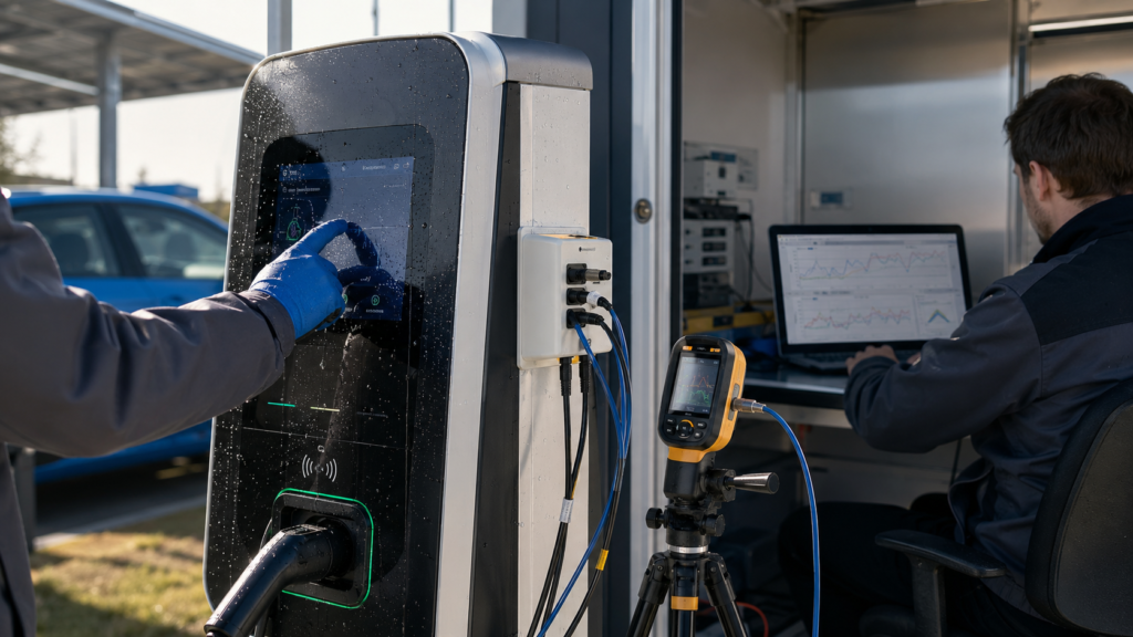
Test the normal interface and every critical state under the expected viewing distance and angle. Include daylight, shade, nighttime operation, reflections, wet cover glass, polarized eyewear if relevant, minimum and maximum brightness states, language variants, QR codes, warnings and error messages.
Verify dry and wet operation, specified gloves, edge accuracy, false-touch rejection, repeated use, cleaning, electrical-noise conditions, startup, sleep and recovery. Record the touch-controller firmware and tuning configuration used for the approved sample.
Test cold start, warm restart, power interruption, brownout behavior, application crash recovery, network loss, backend reconnection, display-cable interruption where safely testable, touch reconnection, brightness transitions and software update recovery.
The released configuration should identify the LCD model and revision, touch sensor, touch controller, cover drawing, bonding process, controller-board revision, cable drawing, backlight circuit, firmware or BSP, device tree, application build and production test procedure.
A prototype that works only with an undocumented bridge register, temporary cable, engineering software image or manually tuned touch file is not yet a controlled production design.
A useful RFQ should describe the required system rather than asking only for an “outdoor EV charger screen.” Provide:
RJY Display can review an existing TFT LCD platform against defined cover-glass, touchscreen, backlight, FPC, interface, controller-board, firmware and mechanical requirements. The practical customization path normally begins with an existing display module rather than the development of an entirely new LCD size or pixel architecture.
A TFT LCD may be suitable when the charger needs a color graphical interface, instructions, status information, QR codes or touch interaction. The exact module must be selected according to the installation environment, optical stack, viewing conditions, host interface, touch requirements, thermal design, enclosure and lifecycle needs.
No single brightness value is correct for every charger. Readability depends on the LCD, backlight, ambient light, reflections, touch sensor, bonding, cover glass, surface treatment, UI contrast, viewing angle and enclosure. The complete assembly should be tested in representative conditions.
No. HDMI cannot passively drive those raw panel interfaces. An active receiver, bridge, scaler or controller board must convert the source video into the timing and electrical format required by the selected LCD while the system separately supplies panel power, initialization and backlight control.
Normally no. In a typical HDMI touch display, HDMI carries video while touch coordinates use a separate connection such as USB. Raw embedded touch controllers may instead use I2C or another supported input interface.
No. OCPP is a communication protocol between a charging station and a charging management system. It is implemented in the charger’s software and network architecture, not by the raw TFT LCD module. The local HMI may display information received from charger control or backend software, but those system roles must remain distinct.
Share your display size, resolution, interface, brightness, touch requirement, controller board requirement, and application environment.
Continue reading related display technology guides and application references.
Talk to RJY’s engineering team for display matching, controller board review, and customization discussion.