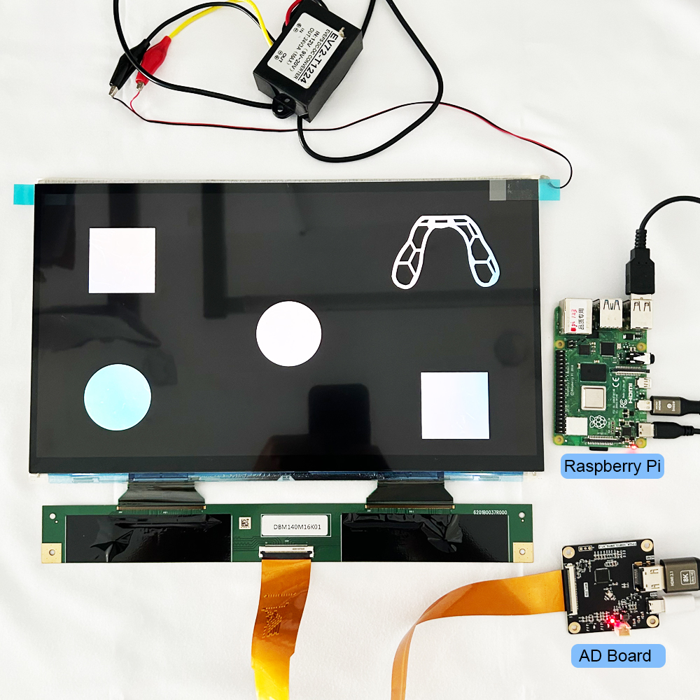
In embedded systems and custom hardware, the display is typically the most sensitive component in the power tree. Driving a thin-film transistor (TFT) liquid crystal display involves more than simply connecting the battery to the VCC pin. Multiple power domains exist between logic gates, LED strings, and liquid crystal bias rails, each requiring specific voltages and strict timing sequences.
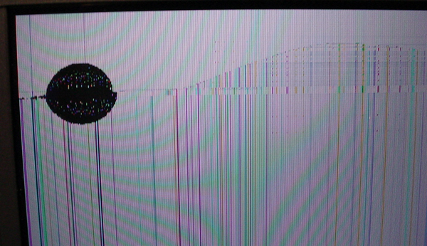
Failure to adhere to these parameters results in “ghosting,” flickering, or even permanent “gate lock-up” damage to the silicon backplane. Therefore, understanding how to properly power up the display is an essential task for both engineers and sales personnel.
1. Deconstructing the Power Domains
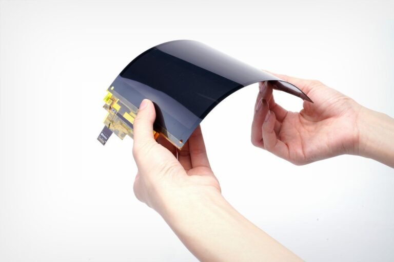
A modern TFT module is essentially three different devices sharing one piece of glass. Each has its own electrical profile:
A. Logic Power(VCC/VDD)
- Voltage: Typically 3.3V. While some legacy 5V modules exist, the industry has standardized on 3.3V to match modern MCUs (ESP32, STM32, ARM).
- Function: Powers the internal controller (e.g., ILI9341, ST7789) and the data interface (SPI/Parallel/RGB).
- Critical Note: If your MCU runs at 5V logic but your TFT is a 3.3V device, you must use a high-speed level shifter (like the 74LVC245) to avoid over-voltaging the display’s CMOS inputs.
B. The Backlight (VBL)
- Nature: Usually an array of white LEDs.
- Requirement: LEDs are current-driven devices. Small displays might have LEDs in parallel (requiring 3.3V @ 60mA), while larger or industrial displays put them in series (requiring 12V–24V @ 20mA).
- Control: Never drive a backlight directly from a GPIO. Use a dedicated Constant-Current LED Driver or a MOSFET-switched PWM circuit.
C. Bias Rails (AVDD, VGH, VGL, VCOM)
- Advanced Panels: Industrial and high-resolution panels require specific voltages to twist the liquid crystals.
- VGH: ~+15V to +20V
- VGL: ~-7V to -10V
- Generation: Most hobbyist modules integrate “Charge Pump” circuits on the flex cable to generate these from the 3.3V rail. However, bare industrial panels require an external PMIC (like the TPS65150).
2. Power Sequencing: The Golden Rule
Liquid crystals are susceptible to DC polarization. If you apply data signals before the logic is stable, or leave the bias rails on after the logic is killed, you can cause permanent “burn-in.”
The Standard Turn-On Sequence:
- $V_{CC}$ (Logic): Turn on and wait for stability (usually 10ms–50ms).
- Reset: Pull the
RST pin high.
- Software Initialization: Send the “Wake Up” and “Display On” commands via SPI/Parallel.
- Rétroéclairage : Enable the backlight last. This prevents the user from seeing “garbage data” or flickering during the boot phase.
The Shutdown Sequence: Reverse the order. Turn the backlight off first, then send the “Sleep” command, then kill VCC.
3. Practical Implementation Scenarios
Scenario A: The Prototyping Setup (ESP32/Arduino)
For a standard 2.8″ SPI display, the logic can be pulled from the 3.3V regulator of the MCU. However, the backlight should be powered via a BJT or MOSFET (like the 2N7002) connected to a PWM-capable pin for brightness control.
Warning: Attempting to power a 100mA backlight directly from an MCU pin will eventually brown out the processor or fry the GPIO.
Scenario B: Battery-Powered Wearables
When running off a Li-Po battery (3.7V–4.2V), you need two paths:
- Step-Down (Buck): A high-efficiency regulator to drop the battery voltage to a steady 3.3V for logic.
- Step-Up (Boost): A boost converter to generate the ~12V–19V required for series-connected backlight LEDs.
4. Hardware Integrity Best Practices
- Decoupling: Place a 10µF tantalum and a 0.1µF ceramic capacitor as close to the display’s $V_{CC}$ pin as possible. This suppresses the switching noise from the TFT’s internal charge pumps.
- Ground Plane: Separate your “Dirty Ground” (backlight PWM switching) from your “Clean Ground” (SPI/I2C logic). Join them at a single point (Star Ground) near the power supply.
- EMI Mitigation: For long ribbon cables (FPC), add a 10–50 Omega series resistor on the data lines to dampen signal reflections and EMI.
Questions fréquemment posées
Q: Why is my TFT screen white even though it’s powered?
A : A “White Screen” usually means the backlight is on, but the logic isn’t initialized. Check your $V_{CC}$ levels and ensure your software reset sequence matches the datasheet.
Q: Can I use a current-limiting resistor for the backlight?
A : For small displays (under 2.4″), a small resistor (e.g., 10–22 $\Omega$) is acceptable for 3.3V power. For anything larger, you must use a constant-current driver to prevent thermal runaway and brightness fluctuations as the LEDs heat up.
Q: My display flickers when the SD card is reading. Why?
A : Backlights and SD cards are both “bursty” power consumers. Your 3.3V rail is likely sagging during the SD read. Use a larger bulk capacitor (100µF+) on the power rail or use separate regulators.
Ressources de référence
Newhaven Display: TFT LCD Support and Knowledge Base
DisplayMate: Display Technology Comparisons
Texas Instruments: TPS65150 Datasheet (TFT Power Solutions)
STMicroelectronics: AN4861: LCD-TFT Display Controller Application Note