Facing a bottleneck in your Embedded Display Project?
Don’t let complex integration or supply chain issues slow your time-to-market. Book a free consultation with the RJY expert team for tailored design and manufacturing support.

In the world of embedded systems engineering, the interface between your logic and your user is everything. As graphical interfaces move from simple character LCDs to high-resolution TFTs, the choice of communication protocol becomes a pivot point for project success. Among the options, spi displays have emerged as the “Goldilocks” solution—balancing speed, complexity, and cost.
Whether you are a professional developer working on an industrial HMI or a hobbyist perfecting a retro gaming handheld, this exhaustive guide explores every technical facet of spi displays.
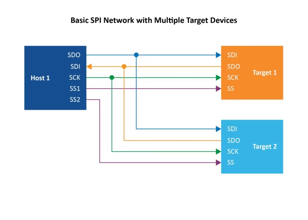
To understand the value of spi displays, one must first understand the “Serial Peripheral Interface” protocol itself. SPI is a synchronous, full-duplex, four-wire serial data link. In a display context, the microcontroller (Master) dictates the timing, and the display controller (Slave) receives the pixel data.
A standard interface for spi displays typically consists of the following:
Not all spi displays are created equal. They operate on different “Modes” (Mode 0 through Mode 3) depending on the clock polarity (CPOL) and phase (CPHA). Most modern drivers like the ILI9341 default to Mode 0, where data is sampled on the rising edge of the clock.
The single biggest “Pro” for spi displays is speed. While the I2C communication protocol is limited to roughly 400kbps, a hardware SPI bus can easily sustain 20Mbps to 40Mbps.
Let’s look at the math for a standard 320×240 TFT:
Total Pixels: $320 \times 240 = 76,800$
Bits per Pixel (RGB565): $16$ bits
Total bits per frame: $1,228,800$
On a 400kHz I2C bus, it would take 3.07 seconds to draw one frame. On a 20MHz SPI bus, it takes only 0.06 seconds, enabling a smooth 16 FPS. With DMA (Direct Memory Access), this jumps even higher.
From the low-power MSP430 to the high-performance STM32 series, almost every MCU has a dedicated hardware SPI peripheral. This means spi displays are incredibly portable across different hardware ecosystems.
Compared to parallel display interfaces (which require 8, 16, or 24 data lines), spi displays require only 4 to 6 lines. This significantly reduces the complexity of multi-layer PCB design and minimizes the risk of trace length mismatches and signal skew.
While simpler than parallel, spi displays are “pin-hungry” compared to I2C. A typical setup (CS, DC, RST, SCK, MOSI, BL) consumes 6 GPIO pins. On a small-form-factor MCU like the ATtiny, this might represent 75% of your available I/O.
SPI is not a differential signal (unlike USB or Ethernet). As your clock speeds increase, the signal becomes highly sensitive to electromagnetic interference (EMI). If your spi displays are more than 15cm away from the MCU, you will likely encounter:
In I2C networking, each device has a software address. In SPI, you need a physical Chip Select (CS) pin for every device. If you are building a complex IoT gateway with multiple sensors and two spi displays, your pin management becomes a logistical nightmare.
Choosing the right controller for your spi displays is as important as the protocol itself. Here is a breakdown of the “Big Three” in the industry:
| Driver Chip | Display Type | Max Resolution | Best Use Case |
| ILI9341 | TFT LCD | 320×240 | Most common, massive library support. |
| ST7789 | IPS LCD | 240×240 | Superior colors, high-speed SPI (50MHz+). |
| SSD1306 | OLED | 128×64 | Low power, high contrast, great for wearables. |
The ILI9341 is the king of spi displays. It is the most documented chip in the world. If you encounter a bug, there is a 99% chance a fix exists on the Arduino forums. It supports a wide range of orientations and has built-in gamma correction.
If you want your spi displays to feel as responsive as a smartphone, you cannot rely on standard “bit-banging” libraries. You must utilize Direct Memory Access (DMA).
Normally, the CPU has to “hand-carry” every byte of pixel data to the SPI buffer. This consumes 100% of the CPU’s attention. With DMA optimization, the CPU simply tells the DMA controller: “Here is the memory address of my image; go send it to the SPI display while I do something else.”
For high-end microcontroller projects (like those using the ESP32-S3 with PSRAM), you can implement Double Buffering.
One of the most common reasons spi displays fail in the field is improper hardware integration.
Most spi displays (especially TFTs) are 3.3V devices. If you connect them directly to a 5V Arduino Uno, you will likely fry the display’s logic gates.
The Solution: Always use a logic level shifter (like the 74LVC245) or a dedicated voltage divider for the SCK and MOSI lines.
The backlight of a 3.5-inch spi display can pull up to 150mA. This is often more than an MCU’s LDO regulator can handle without overheating.
When your screen remains white or displays “static,” follow this checklist:
SPI_CLOCK to 4MHz for testing.In projects like the GameBoy Nano, the use of spi displays is mandatory. The high FPS allows for 60Hz scrolling, while the low pin count leaves enough GPIOs for the D-pad and buttons.
For an industrial IoT dashboard, reliability is key. Spi displays provide a more robust connection than I2C in environments with heavy motor noise, especially when paired with shielded cables.
Q: Can I run spi displays over a long distance?
A: Not easily. Standard SPI is intended for “on-PCB” or “short-cable” communication. For distances over 1 meter, you should consider RS485 or converting the SPI signal to differential pairs using a dedicated driver chip.
Q: Why is my SPI display so much slower on Arduino Uno than ESP32?
A: The Arduino Uno has an 8-bit processor running at 16MHz, with a maximum SPI clock of 8MHz. The ESP32 is a 32-bit processor running at 240MHz with an 80MHz SPI clock. The raw processing power makes a massive difference in how fast the embedded GUI libraries can calculate pixel data.
Q: Do spi displays support touchscreens?
A: Yes. Many modules come with an XPT2046 touch controller on the same board. These controllers usually have their own SPI interface, which shares the MOSI/MISO/SCK lines with the display but requires a separate CS pin.
Q: What is the best software library for beginners?
A: If you are using an Arduino-compatible board, start with Adafruit_GFX. If you need professional speed on an ESP32 or STM32, move to TFT_eSPI or LVGL.
The decision to use spi displays comes down to the balance of your project’s needs. If you require high frame rates, vibrant colors, and have a moderate amount of GPIO pins available, the SPI protocol is unbeatable. While it requires more attention to signal integrity and logic level shifting than simpler interfaces, the performance gains are undeniable.
By mastering DMA optimization and choosing the right driver (like the ST7789), you can transform a simple microcontroller project into a high-end graphical experience.
Share your display size, resolution, interface, brightness, touch requirement, controller board requirement, and application environment.
Continue reading related display technology guides and application references.

Explore product pages related to this article topic.
Talk to RJY’s engineering team for display matching, controller board review, and customization discussion.









