Facing a bottleneck in your Embedded Display Project?
Don’t let complex integration or supply chain issues slow your time-to-market. Book a free consultation with the RJY expert team for tailored design and manufacturing support.

A variable-frequency-drive control panel may include a motor drive, control electronics, communications, power conversion, cooling, wiring, enclosure hardware, and an operator interface. A TFT LCD can make that interface clearer and easier to use, but it is only one layer of the completed system.
For an equipment manufacturer, the selection question is not simply whether a display can show speed, alarms, or a parameter page. The display must fit the operator workflow, the available host interface, the cabinet construction, the intended touch behavior, and the electrical environment created by the surrounding equipment.
This guide explains how to evaluate a TFT LCD for an industrial VFD control panel HMI without treating the display, touch sensor, drive-control logic, motor power stage, and safety functions as interchangeable.
An HMI helps an operator view machine state and issue permitted requests. A VFD or motor-drive control system manages the motor-drive functions defined by the equipment design. The power stage handles energy conversion for the motor. These functions can be packaged in one cabinet, but they should be specified as separate layers.
The TFT LCD displays information. The touch sensor or physical controls report user input. An embedded host or HMI controller renders the interface and handles the application layer. The drive-control architecture determines how operator requests are interpreted, permitted, communicated, and acted upon. The display itself does not provide motor-control performance, safe stopping, electrical isolation, or EMC compliance.
This distinction is particularly important when requirements are written. “The screen must control the VFD” is not a useful engineering requirement. A better requirement identifies the intended operator action, the command path, the allowed machine state, the response presented to the operator, and the defined recovery behavior.
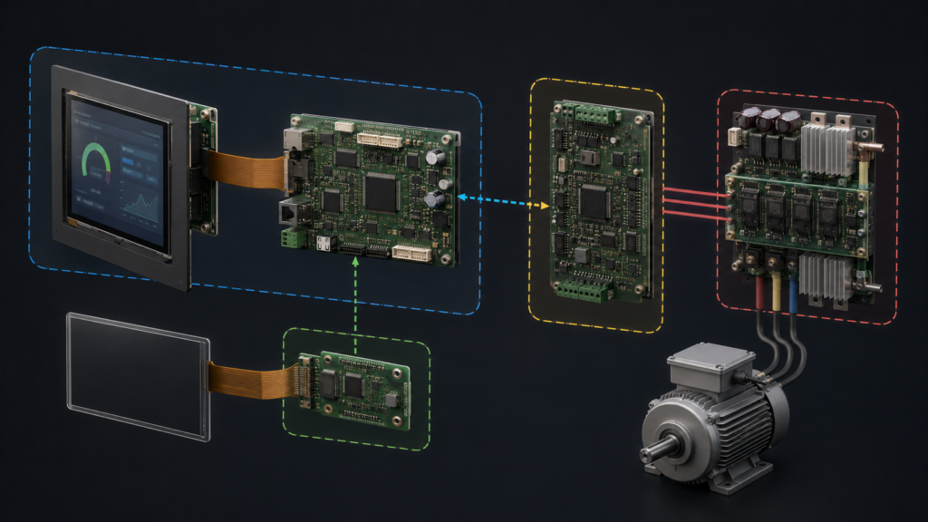
Industrial HMI design is generally concerned with presenting information that enables operators to monitor and interact with equipment; it is not synonymous with the underlying power or automation control layer.1
Panel size and resolution should follow the operator’s real tasks. A compact drive controller may need only a clear running state, a selected speed reference, local or remote status, alarm acknowledgement, and guided setup. A larger equipment panel may need multiple motors, process values, trends, maintenance views, recipe selection, permissions, and diagnostic pages.
Create representative screens before selecting the display. Include the actual number of values, alarm messages, navigation depth, language requirements, touch targets, and operating distance. This exposes whether the HMI needs a compact native TFT, a larger panel-mounted display, or a separate engineering service interface.
Do not assume that every parameter belongs on the normal operator screen. A useful drive-panel HMI makes the current machine state, active mode, alarm priority, and permitted next action understandable. Advanced configuration should be deliberately separated from normal operation according to the equipment’s documented access-control and risk-management approach.
A raw TFT LCD module normally uses a native display interface such as RGB, LVDS, MIPI DSI, or eDP. The selected HMI host must support the exact panel interface, timing, pixel format, voltage requirements, connector arrangement, initialization sequence, backlight control, and software configuration.
Interface selection cannot be based on connector appearance alone. Before selecting samples, verify the panel datasheet and host documentation together: pin assignment, display timing, image orientation, power-up sequence, driver support, FPC routing, backlight enable behavior, and long-term availability expectations.
If a host provides HDMI while the intended TFT module uses a raw MIPI DSI, RGB, LVDS, or eDP input, a passive cable cannot convert the source into the native panel interface. The project requires an active controller or bridge compatible with both the source and the specific panel. That active hardware becomes part of the power, firmware, startup, thermal, mechanical, and lifecycle design.
Processor display peripherals also require matching software support. For example, NXP’s LCD interface documentation describes a display-interface driver within a defined software environment; it does not make unrelated boards and panels inherently compatible.2
A touchscreen is not the same electrical path as the panel video interface. A projected-capacitive or resistive touch sensor has its own controller, connection, firmware, grounding considerations, and host software path. The TFT interface carries pixels to the panel; the touch system reports user input back to the host.
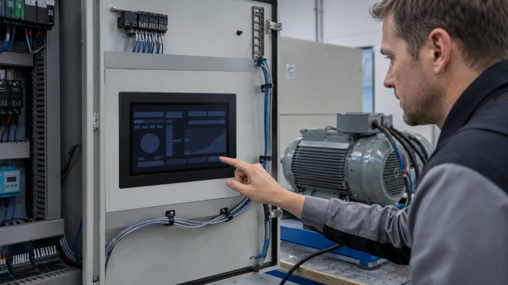
Touch selection should be based on the expected use condition. Consider glove type, contamination, cleaning process, moisture, touch-target size, cover-lens material, grounding arrangement, nearby equipment, and the consequences of unintended input. For frequently used or safety-relevant machine actions, physical controls may be required by the completed equipment design; that decision is separate from choosing a display module.
Evaluate the touch stack in the intended cabinet door or front panel. A bench demonstration with a bare module does not validate touch response after the final cover lens, mounting frame, wiring, and nearby electrical equipment have been introduced.
The display must fit the final cabinet, not only an open development bench. Review the visible area, cutout, cover lens, mounting method, panel thickness, gasket or sealing strategy where applicable, connector access, cable routing, FPC bend limits, service approach, and thermal environment around the completed assembly.
A practical control-panel architecture usually separates the low-power HMI electronics from the higher-energy drive and motor wiring as required by the system design. The exact cabinet layout, protective measures, cable routing, grounding, shielding, filtering, insulation coordination, and test program must be defined by qualified engineers for the finished equipment.
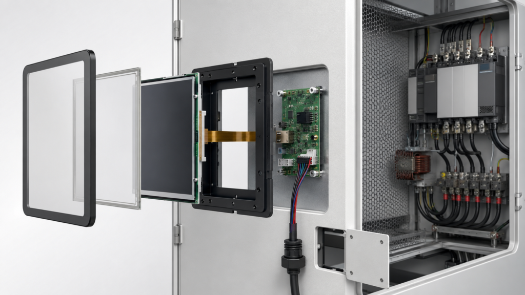
Variable-speed drive systems can be subject to EMC requirements under applicable standards, but a TFT module does not establish compliance on its own. The relevant drive system, enclosure, wiring, connected equipment, and intended installation need their own compliance evaluation.3
The display should remain readable in the real installation position. Assess viewing distance, mounting angle, reflections from factory lighting, operator height, ambient light, and whether the user must read information while standing beside moving equipment. Brightness, contrast, viewing-angle behavior, surface treatment, and cover-lens choices must be evaluated against the intended environment rather than selected from a generic checklist.
Also define what the interface should show during startup, communication loss, host restart, drive fault, and recovery. A stale speed value or frozen status screen can create confusion. The finished HMI application should make its state and communication condition clear within the equipment’s broader design.
Graphics requirements should be written around the operator workflow. A panel that only presents status and a limited parameter set has different host, memory, and update requirements from an HMI that displays multiple trends, diagnostics, service documentation, or remote-support screens.
Validation should use the intended display, touch stack, host board, cabinet construction, harness, application software, motor-drive equipment, and representative operating conditions. The purpose is to confirm that the operator interface works as designed in context; it is not to infer motor performance or safety compliance from the display selection alone.
A project-specific validation plan can cover representative GUI content, viewing positions, ambient lighting, intended touch conditions, power-up behavior, backlight operation, touch initialization, communication interruption, cabling retention, service access, and recovery after expected faults. Acceptance criteria should be written before design freeze.
Terms such as “readable,” “fast response,” and “glove operation” need context. Define the viewing condition, content type, expected interaction, target size, glove or contamination condition, and required recovery behavior so the display-integration decision is testable.
For a VFD control-panel display review, provide the cabinet drawing, target active area, display orientation, representative GUI, host processor or board, available native display interfaces, touch requirements, cover concept, expected lighting, cable constraints, power sequence, project stage, and estimated demand range.
RJY Display can review applicable existing display platforms and project-specific integration options around touch, cover lenses, backlight, interface, FPC, controller-board coordination, and mechanical fit. Feasibility depends on the confirmed module and application requirements. It should not be interpreted as a commitment to create any arbitrary LCD cell size from zero or to qualify a completed motor-drive system.
Request a VFD control-panel display compatibility review with the panel, host, interface, touch, optical, and mechanical requirements so the display layer can be evaluated in its proper system context.
No. A TFT LCD presents information. The HMI host, drive-control architecture, power stage, and completed equipment design determine how operator requests are handled and how the motor is controlled.
No. A passive cable cannot convert HDMI into a raw MIPI, RGB, LVDS, or eDP panel interface. A compatible active controller or bridge is required and must support the source and the exact panel requirements.
No. The touch sensor normally has a separate controller, connection, firmware, and software path. The display interface drives pixels to the panel, while the touch system reports user input to the host.
No. EMC compliance depends on the completed drive system, cabinet, wiring, connected equipment, intended installation, and applicable evaluation process. A display module alone does not establish system compliance.
Provide the cabinet drawing, target active area, representative GUI, host platform, native display interface options, touch and cover requirements, lighting conditions, cable constraints, power sequence, project stage, and expected demand range.
Share your display size, resolution, interface, brightness, touch requirement, controller board requirement, and application environment.
Continue reading related display technology guides and application references.
Talk to RJY’s engineering team for display matching, controller board review, and customization discussion.