Facing a bottleneck in your Embedded Display Project?
Don’t let complex integration or supply chain issues slow your time-to-market. Book a free consultation with the RJY expert team for tailored design and manufacturing support.

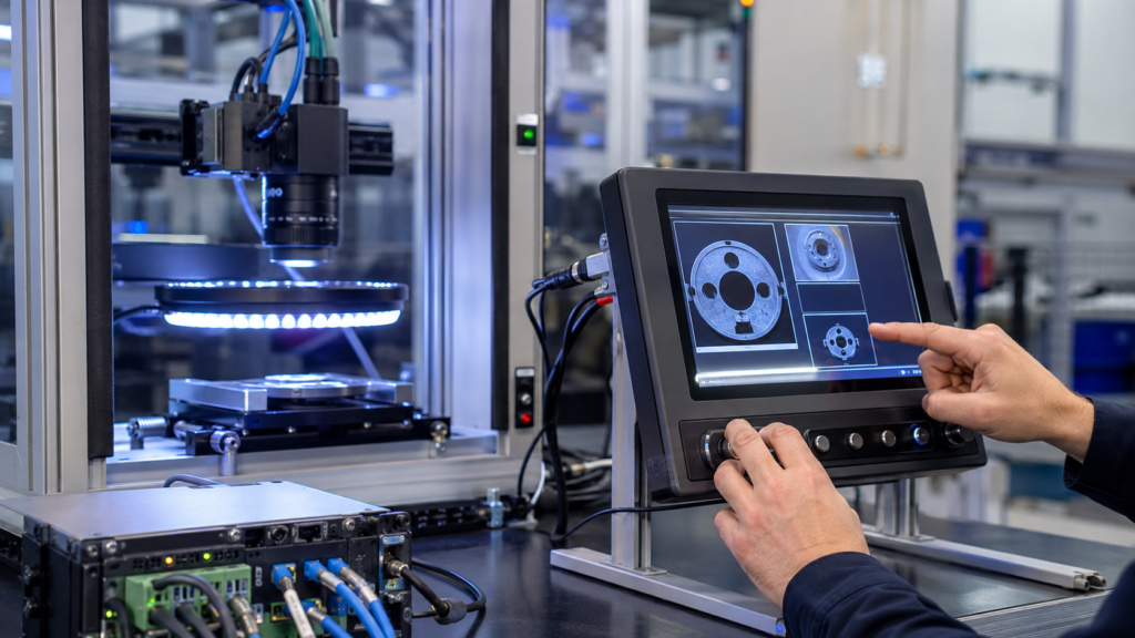
A machine vision inspection system may combine industrial cameras, controlled illumination, optics, image acquisition, vision software, motion or machine controls, and an operator interface. The TFT LCD is important to that system, but it is not the camera, the inspection algorithm, or proof that a defect decision is correct.
For an equipment OEM, the useful question is not simply “Which display has the highest resolution?” It is how the display supports the operator’s real workflow: starting the machine, selecting approved recipes, reviewing images where appropriate, understanding machine state, responding to alarms, and recovering from defined faults without confusing the display layer with the inspection function itself.
This guide explains how to select a TFT LCD and its supporting HMI architecture for a machine vision inspection system while keeping the camera path, vision computer, touch input, external monitor, and embedded display interfaces distinct.
A practical inspection machine contains several different paths. The camera and illumination create the image-acquisition path. A vision computer or embedded processing platform receives and processes image data. The HMI presents operator information and accepts input. In some projects, a separate external monitor is used for engineering review, commissioning, or image analysis.
These functions may share an enclosure, but they should not be treated as interchangeable. A TFT LCD does not capture the inspected image, and a touch panel does not perform image processing. Likewise, a large external monitor can be useful for setup or detailed review without being the same product as a compact embedded machine HMI.
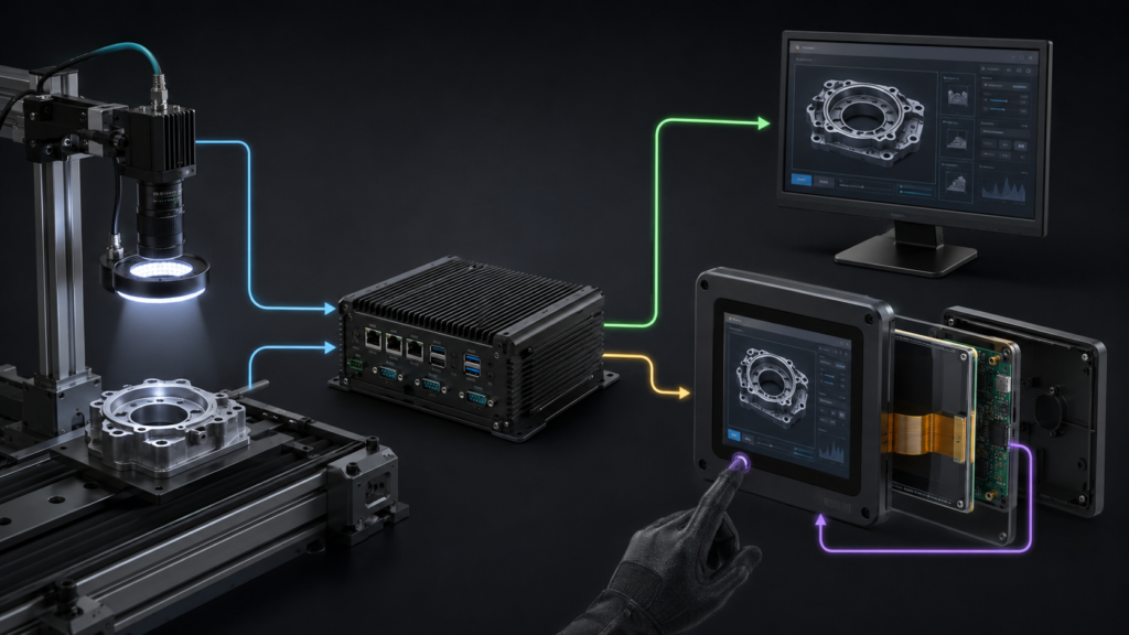
Machine-vision camera software often uses defined camera-control and transport interfaces. For example, GenICam is intended to provide a common programming interface for cameras across several interface technologies.1 That camera-facing software interface is separate from the native electrical interface used to drive an LCD panel.
Documenting these boundaries early prevents common specification errors, such as requesting an LCD module to “support the camera,” assuming a touch display provides the inspection software, or treating an HDMI connector as universal compatibility with a raw panel.
The display requirements should follow the operator’s task sequence. An automated optical inspection station may need a clear ready state, current recipe identification, guarded setup functions, alarm priority, production state, image-review controls, and maintenance information. A packaging inspection machine may need different emphasis from a precision assembly or surface-defect system.
Build representative screens using the actual information hierarchy. Include realistic part images, overlays where the application requires them, thumbnail review areas, alarms, recipe names, machine state, operator permissions, and translations. This helps the team decide whether the interface needs a compact embedded display, a wider format, a separate review monitor, or a combination of these elements.
Do not equate camera resolution with HMI resolution. A high-resolution camera can acquire substantially more data than an operator needs to view continuously. The operator display may show a scaled live image, a selected region, a review image, or only the machine state. The correct panel resolution depends on viewing distance, font size, decision complexity, image-review workflow, graphics performance, and the host’s ability to update the user interface reliably.
Inspection equipment can present a large amount of information. A useful HMI must make the next operator action understandable without forcing the user to interpret every camera image or diagnostic detail. Place the most time-sensitive machine state and alarm information where it remains visible during normal operation. Use image areas, thumbnails, controls, and engineering views only when they support a defined task.
Visual hierarchy matters when an operator is standing at the machine, wearing gloves, or working under changing factory lighting. Consider the normal viewing distance, screen mounting angle, reflections from overhead luminaires, expected operator position, and whether the user must make selections while monitoring the process.
The application should clearly distinguish displayed information from the machine’s approved decision logic. A colored status region or a displayed image can communicate a result determined by the completed system, but the LCD itself does not establish detection performance, traceability, measurement accuracy, or machine safety.
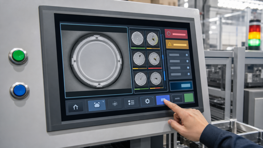
A hybrid input arrangement is often worth evaluating. Touch is useful for flexible navigation, image movement, setup menus, and contextual controls. Physical keys, rotary controls, or dedicated machine controls may be preferable for frequent actions or workflows requiring tactile feedback. Their use must be determined by the equipment design and its risk controls.
Raw TFT LCD modules commonly use a native interface such as RGB, LVDS, MIPI DSI, or eDP. The selected HMI host must support the exact panel interface, timing, power sequence, pixel format, connector arrangement, backlight control, operating-system driver, and software configuration.
A connector that appears to fit is not proof of compatibility. Engineers should verify the panel datasheet, pin assignment, voltage levels, lane or bus configuration, initialization sequence, display timing, orientation handling, and touch-controller connection before sample selection.
If the chosen host provides HDMI while the LCD module requires raw MIPI DSI, RGB, LVDS, or eDP, a passive cable cannot make the conversion. The design needs an active controller or bridge that is compatible with both the video source and the exact panel. That active device becomes part of the electrical, firmware, startup, thermal, EMC, and lifecycle plan.
Display-controller documentation also illustrates why the graphics path must be specified deliberately. NXP’s LCD-interface documentation, for example, describes an LCDIF peripheral driver used with a display interface; it does not imply that every processor, panel, cable, or software stack is mutually compatible.2
A projected-capacitive touch sensor, resistive touch sensor, or other input method has its own controller, firmware, connection, grounding requirements, and software path. It does not carry the panel’s pixel data. Similarly, the LCD video connection does not by itself define touch behavior.
Touch selection should reflect the actual operating condition: gloves, contamination, cleaning materials, moisture, target size, grounding, enclosure materials, and electrical noise. A generic statement that a panel “has capacitive touch” is not enough to establish reliable use in a particular inspection machine.
Evaluate touch with the intended cover stack and enclosure. Check deliberate taps, edge targets, drag actions, rejected touches, recovery after power cycling, and the effect of nearby equipment. If the project needs physical controls for specific machine actions, treat their electrical and functional requirements separately from the display module.
The vision computer may be busy acquiring images, applying inspection logic, recording results, communicating with automation controls, and updating the HMI. A display requirement should therefore be written around the intended operator experience, not around an unsupported assumption that every camera frame must be rendered at full resolution on the TFT.
Define what the operator needs to see during automatic operation, changeover, setup, fault recovery, and maintenance. Consider whether image presentation is live, event-driven, stored for later review, scaled to fit, or handled on a separate engineering monitor. The answer affects framebuffer memory, graphics bandwidth, host processing load, storage behavior, and UI design.
Also define startup and fault behavior. The user should not mistake a frozen image, stale recipe indication, or delayed communication screen for a current inspection state. Review power-on sequencing, display availability, backlight enable, host startup, touch initialization, loss of camera communication, and controlled recovery as system-level behavior.
The finished HMI must fit the machine, not merely operate on an open development bench. Review the enclosure window, active area, viewing angle, cover glass, mounting, connector access, FPC bend radius, strain relief, service approach, internal cable routing, and thermal conditions around the final assembly.
Factory lighting can introduce reflections that are not obvious in a desk test. Use the real mounting angle and representative illumination when evaluating readability. If the enclosure includes a touch layer or cover lens, assess the completed optical stack rather than relying only on a bare-panel specification.
Machine wiring, cameras, lighting controllers, motors, and power supplies can create an electrically demanding environment. The TFT, backlight, touch controller, host board, power conversion, grounding, shielding, connectors, and external harness all need a project-specific integration review. A display module alone does not define the machine’s EMC performance or environmental suitability.
Validation should progress from electrical bring-up to the intended enclosure, host, touch stack, cables, application software, and inspection equipment. The goal is to confirm that the operator interface works under representative conditions; it is not to infer inspection accuracy or compliance from the presence of a display.
A practical validation plan can include representative screen content, image-display behavior under expected graphics load, operator viewing positions, ambient lighting, intended touch conditions, physical-control operation, connector and harness retention, power interruption and restart, camera and host communication loss, and service access.
Write acceptance criteria before design freeze. Phrases such as “real-time display,” “glove operation,” or “easy to read” need defined context: the image content, expected response, lighting condition, glove type, target size, user position, and recovery condition.
When requesting an HMI display review, provide the enclosure drawing, target active area, orientation, representative GUI, host processor or board, available native display interfaces, desired touch behavior, cover concept, viewing distance, factory-lighting conditions, image-review workflow, cable constraints, power sequence, project stage, and expected demand range.
RJY Display can review applicable display platforms and customization around existing modules, such as touch, cover, backlight, interface, controller-board, FPC, and mechanical coordination. Feasibility depends on the confirmed module and project requirements. It should not be interpreted as a promise to create any arbitrary LCD cell size from zero or to qualify a complete vision system.
Contact RJY Display for a machine vision HMI display review with the camera, host, interface, optical, touch, mechanical, and operator-workflow requirements so the display layer can be evaluated in its proper system context.
No. Camera resolution and operator-display resolution serve different purposes. The HMI should be selected for the information, image detail, viewing distance, and workflow that the operator must handle. A system may scale images, show selected regions, or use a separate monitor for detailed review.
No. The LCD presents information. Image acquisition, processing, defect logic, result handling, and machine control belong to the camera, illumination, vision computer, software, and completed equipment architecture.
No. A passive cable cannot convert HDMI into a raw MIPI, RGB, LVDS, or eDP panel interface. A compatible active controller or bridge is required and must support the source and exact panel requirements.
No. Touch input normally uses a separate sensor, controller, connection, firmware, and software path. The video interface drives pixels to the LCD, while the touch system reports user input to the host.
Provide the enclosure and active-area target, representative GUI and image workflow, host platform, native interface options, touch and cover requirements, mounting and lighting conditions, cable constraints, power sequence, project stage, and expected demand range.
Share your display size, resolution, interface, brightness, touch requirement, controller board requirement, and application environment.
Continue reading related display technology guides and application references.
Talk to RJY’s engineering team for display matching, controller board review, and customization discussion.