Stehen Sie bei Ihrem Embedded-Display-Projekt vor einer Herausforderung?
Lassen Sie nicht komplexe Integration oder Lieferkettenprobleme Ihre Markteinführung verzögern. Vereinbaren Sie eine kostenlose Beratung mit dem RJY-Expertenteam für maßgeschneiderte Design- und Fertigungsunterstützung.
So wählen Sie ein TFT-LCD für die HMI einer Industriekühlmaschine aus
Veröffentlicht:
11 Minuten Lesezeit
Aktualisiert:
Eine industrielle Wasserkältemaschine kann Kältemittel- und Wasserkreisläufe, Sensoren, Aktoren, eine Gerätesteuerung, Verdichter, Pumpen, optionale Frequenzumrichter, Kommunikations-Gateways und eine Gebäudeautomationsanbindung kombinieren. Ein lokales TFT-Display kann den Betrieb und die Wartung der Anlage erleichtern, ist jedoch nicht die Kältemaschinensteuerung, der Motorantrieb, die BACnet-Schnittstelle, das Schutzsystem oder die entfernte Gebäudemanagement-Workstation.
Die Display-Auswahl sollte daher mit der Arbeit beginnen, die direkt an der Kältemaschine ausgeführt wird. Bediener benötigen möglicherweise eine prägnante Geräteübersicht. Inbetriebnahme-Ingenieure benötigen möglicherweise Anlauf- und Kommunikationsinformationen. Servicepersonal benötigt möglicherweise Alarmhistorie, Subsystemstatus und eine geführte Wartungsnavigation. Diese Aufgaben bestimmen die nutzbare aktive Fläche, Auflösung, Eingabemethode, Host-Architektur, optischen Aufbau, Montage und den Validierungsplan.
Dieser Leitfaden erläutert, wie ein TFT-LCD für eine industrielle Kältemaschinen-HMI ausgewählt wird, während die Grenzen zwischen dem Rohdisplay, der Touch-Eingabe, dem eingebetteten HMI-Host, der Kältemaschinensteuerung, dem optionalen Antrieb, dem Gebäudenetzwerk und der entfernten BAS eingehalten werden.
Trennen Sie die lokale Anzeige von der Kältemaschinensteuerung und der Gebäudeautomation (BAS)
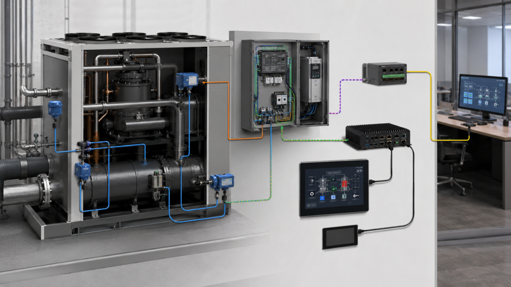
Ein praktisches Architekturdiagramm sollte jede funktionale Ebene identifizieren, bevor ein Display-Muster ausgewählt wird. Sensoren liefern Informationen an die entsprechende Gerätesteuerung. Die Kältemaschinensteuerung führt die Steuerungslogik des Herstellers aus und koordiniert die Maschine innerhalb ihrer konstruktiven Betriebsgrenzen. Separate Antriebe können Motoren steuern. Ein Gateway oder eine Steuerungsschnittstelle kann freigegebene Informationen an ein Gebäudeautomationsnetzwerk bereitstellen. Der lokale HMI-Host rendert ausgewählte Informationen auf dem TFT-LCD und interpretiert zulässige Benutzereingaben.
BACnet ist ein Datenkommunikationsprotokoll, das für Gebäudeautomations- und Steuerungssysteme entwickelt wurde, einschließlich HLK-Anwendungen.1 Es kann den Austausch von Objekten, Alarmen, Zeitplänen, Trends und Steuerinformationen unterstützen, ist jedoch keine Display-Video-Schnittstelle. Ein Roh-TFT-LCD empfängt keine BACnet-Nachrichten und wandelt diese nicht selbstständig in Pixel um.
Die Dokumentation der Kältemaschinensteuerung des Erstherstellers zeigt ebenfalls, dass lokale und Netzwerkzugriffspfade verwandt, aber getrennt sind. Daikin Applied dokumentiert Kältemaschinensteuerungspunkte, die über eine lokale HMI und über definierte BACnet- oder Modbus-Schnittstellen zugänglich sein können, wobei die Verfügbarkeit von der jeweiligen Schnittstelle und Implementierung abhängt.2 Dies bedeutet nicht, dass jede Kältemaschine dieselbe Architektur verwendet, zeigt jedoch, warum der lokale Bildschirm, die Gerätesteuerung, die Kommunikationsschnittstelle und die entfernte Workstation nicht als austauschbar behandelt werden sollten.
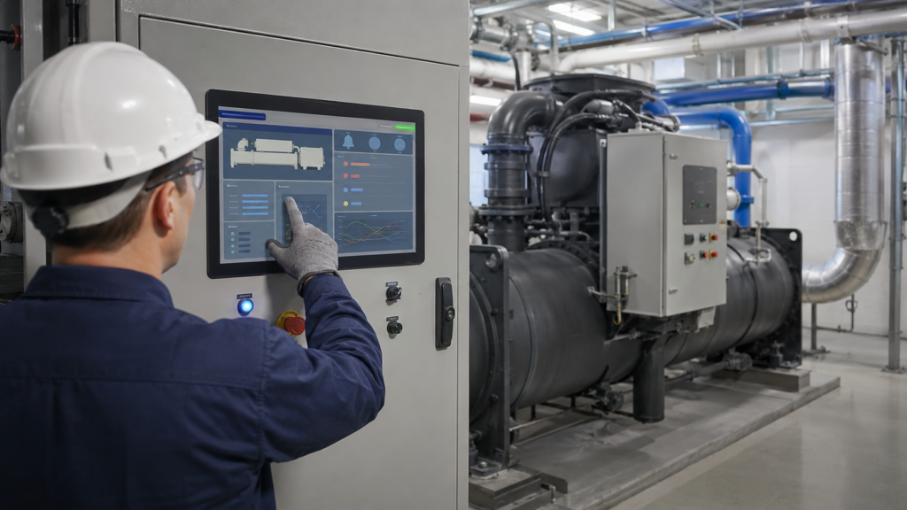
Serviceingenieur unter Verwendung einer Kältemaschinen-TFT-HMI mit Gerätestatus, Alarm- und Wartungsbereichen
Das TFT-LCD stellt nur Pixeldaten dar, die über seinen kompatiblen Display-Pfad geliefert werden. Es misst keinen Kältemitteldruck, bestimmt keine Austrittswassertemperatur, sequenziert keine Verdichter, validiert keinen Sollwert, schützt keinen Motor und stellt keine Gerätesicherheit her. Diese Verantwortlichkeiten verbleiben im vollständigen Kältemaschinen-Design.
Beginnen Sie mit dem lokalen Bediener- und Service-Workflow
Eine nützliche lokale HMI sollte definierte Entscheidungen an der Maschine unterstützen, anstatt jede Seite einer entfernten BAS-Workstation zu reproduzieren. Beginnen Sie damit, zu dokumentieren, wer sich der Kältemaschine nähert, warum er den Bildschirm benötigt, welche Informationen er anzuzeigen berechtigt ist und welche Aktionen die Gerätearchitektur lokal zulässt.
Eine routinemäßige Bedieneransicht kann die Geräteverfügbarkeit, den Betriebsmodus, aktive Alarme, den aktuellen Kommunikationsstatus und eine begrenzte Anzahl freigegebener Befehle priorisieren. Inbetriebnahme- und Wartungsbenutzer benötigen möglicherweise eine tiefere Navigation, einschließlich Subsystemstatus, Ein- und Ausgangsinformationen, Alarmhistorie, Konfigurationsidentifikation und Serviceverfahren. Der Zugriff auf diese Funktionen sollte durch die Anwendungs- und Steuerungsarchitektur geregelt werden, nicht durch den Touch-Sensor.
Erstellen Sie repräsentative Bildschirme, bevor Sie die Diagonale wählen. Fügen Sie tatsächliche Gerätenamen, lange Alarmmeldungen, mehrere Kreisläufe wo zutreffend, nicht verfügbare Werte, Bestätigungsdialoge, Übersetzungen, Berechtigungszustände, Trends und Anforderungen an die virtuelle Tastatur ein. Platzhalter-Dashboards lassen ein kleines Display oft geeigneter erscheinen, als es mit Produktionsinhalten sein wird.
Kältemaschinen-HMI-Architektur, die Sensoren, Gerätesteuerung, Antrieb, Display-Host, Touch, Netzwerk-Gateway und BAS-Workstation trennt
Die Schnittstelle sollte auch das Betrachten von der Autorisierung unterscheiden. Die Anzeige eines Sollwerts beweist nicht, dass dieser gültig ist. Das Anzeigen eines grafischen Befehls bedeutet nicht, dass das Gerät bereit ist, ihn anzunehmen. Die Anwendung muss die Benutzerrolle, den aktuellen Maschinenzustand, die Steuerungsantwort und jede erforderliche Bestätigung bewerten, bevor sie auf Touch-Eingaben reagiert.
Wählen Sie Größe und Auflösung anhand der realen Betrachtungsbedingungen
Industrielle Kältemaschinen werden oft bedient, während der Benutzer vor einem Schaltschrank steht, anstatt das Display in Tablet-Distanz zu halten. Montagehöhe, Betrachtungsabstand, Schranktiefe, umgebende Rohrleitungen, Servicezugang und persönliche Schutzausrüstung können die nutzbare Bildschirmgröße beeinflussen.
Überprüfen Sie die GUI bei ihren vorgesehenen physischen Abmessungen. Stellen Sie sicher, dass Benutzer die ausgewählte Kältemaschine, den Kreislauf, den Betriebszustand, die Alarmpriorität, die Quelle eines Werts und das Alter der angezeigten Informationen identifizieren können. Touch-Ziele müssen nutzbar bleiben, ohne die Statusinformationen zu überladen oder übermäßige Navigation zu erzwingen.
Die Auflösung sollte lesbare Typografie und notwendige Grafiken unterstützen, ohne eine unnötige Belastung für den eingebetteten Host zu erzeugen. Eine Erhöhung der Pixelanzahl kann die Anforderungen an Framebuffer, Speicherbandbreite, Rendering, Boot-Zeit und thermische Bedingungen erhöhen. Panel-Auflösung, Prozessorfähigkeit, Betriebssystem, Grafik-Framework, Anwendungsverhalten und Lebenszyklusplan sollten gemeinsam bewertet werden.
Ein lokaler eingebetteter Bildschirm muss auch nicht jeden Multi-Geräte-Trend oder Anlagenplan reproduzieren, der auf einer größeren Engineering-Workstation verfügbar ist. Das richtige Display ist dasjenige, das seinen definierten lokalen Workflow zuverlässig unterstützt.
Passen Sie die native TFT-Schnittstelle an den HMI-Host an
Ein Roh-TFT-LCD-Modul kann RGB, LVDS, MIPI DSI, eDP oder eine andere definierte native Schnittstelle verwenden. Ein gemeinsamer Schnittstellenname ist nur der Beginn der Kompatibilität. Panel und Host müssen auch hinsichtlich elektrischer Pegel, Auflösung, Pixelformat, Lane- oder Buskonfiguration, Display-Timing, Initialisierung, Steckerbelegung, Hintergrundbeleuchtungssteuerung und Einschaltsequenz übereinstimmen.
Die Prozessor-Schnittstellendokumentation zeigt, warum diese Parameter für die genaue Plattform bestätigt werden müssen. Die LCDIF-Treiberdokumentation von NXP zeigt beispielsweise Display-Schnittstellenkonfigurationsstrukturen und Timing-Verhalten, anstatt universelle Kompatibilität mit jedem Panel zu behaupten.3 Das Geräteteam muss den ausgewählten Prozessor oder das Rechenmodul, das Panel-Datenblatt, das Kabel, die Firmware, das Betriebssystem und die Display-Konfiguration dennoch verifizieren.
Wenn der HMI-Computer HDMI bereitstellt, während das ausgewählte Roh-TFT MIPI DSI, RGB, LVDS oder eDP erfordert, kann ein passives Kabel die Umwandlung nicht durchführen. Das System erfordert einen aktiven Controller oder eine Brücke, die das Quellformat und die genauen Panel-Anforderungen unterstützt. Dieser Controller wird Teil des Anlauf-, Firmware-, Stromversorgungs-, Hintergrundbeleuchtungs-, thermischen, EMV-, Kabel- und Lebenszyklusplans.
Ein fertiger HDMI-Monitor und ein rohes eingebettetes TFT sind unterschiedliche Liefergegenstände. Der fertige Monitor enthält Empfangs- und Display-Steuerelektronik. Ein Rohpanel hängt von einem kompatiblen nativen Display-Ausgang oder einem bewusst ausgewählten aktiven Umwandlungspfad ab.
Halten Sie die Touch-Eingabe getrennt von den Video- und Steuerungspfaden
Die LCD-Videoschnittstelle überträgt Pixeldaten. Ein projiziert-kapazitives oder resistives Touch-System verwendet einen separaten Sensor, Touch-Controller, elektrische Verbindung, Firmware-Konfiguration und Software-Eingabepfad. Die mechanische Integration von Touch-Sensor und LCD kombiniert diese elektrischen Verantwortlichkeiten nicht.
Die Touch-Anforderungen sollten den tatsächlichen Maschinenraum-Workflow widerspiegeln. Relevante Bedingungen können Handschuhtyp, Kondensation, Oberflächenfeuchtigkeit, Reinigungsmittel, Zielgröße, Abdeckglasdicke, Gehäuseerdung, nahegelegene Leistungselektronik und die Körperhaltung des Bedieners umfassen. Eine allgemeine Aussage, dass ein Modul kapazitives Touch enthält, beweist keinen zuverlässigen Betrieb mit jedem Handschuh oder jeder nassen Oberfläche.
Bewerten Sie bewusste Tippvorgänge, Randziele, Ziehen wo verwendet, abgelehnte Kontakte, Bedienung der virtuellen Tastatur, Startverhalten und Wiederherstellung nach einem Touch-Controller- oder Anwendungsneustart. Führen Sie diese Bewertung mit dem vorgesehenen Abdeckglas, der Verklebung oder dem Luftspalt, den Gehäusematerialien, der Erdung und der Produktionskabelanordnung durch.
Physische Schalter und andere dedizierte Maschinensteuerungen sollten getrennt bleiben, wenn dies durch das Gerätedesign oder die Risikobewertung erforderlich ist. Ein Bildschirmsteuerelement kann durch ein defektes Display, einen Touch-Controller, eine Anwendung, eine Stromschiene oder einen Kommunikationspfad beeinträchtigt werden.
Unterscheiden Sie die lokale HMI von einer entfernten BAS-Workstation
Eine lokale Kältemaschinen-HMI und eine entfernte Gebäudeautomations-Workstation können Informationen anzeigen, die von derselben Anlage stammen, bedienen jedoch in der Regel unterschiedliche Benutzer und Kontexte. Die lokale Schnittstelle ist physisch einer Maschine zugeordnet und kann während Inbetriebnahme, Inspektion, Fehlersuche oder kontrollierter Wartung verwendet werden. Die BAS-Workstation kann viele Kältemaschinen, Pumpen, Luftbehandlungsanlagen, Zähler und Gebäudezonen aggregieren.
Das lokale Display sollte seine aktuelle Geräteidentität und seinen Kommunikationsstatus klar machen. Die entfernte Workstation kann eine andere Navigationshierarchie, ein anderes Berechtigungsmodell, einen anderen Alarm-Workflow und ein anderes Datenaufbewahrungssystem verwenden. Kein Bildschirm sollte als synchronisierte Steuerung, Redundanz oder Failover angenommen werden, nur weil beide verwandte Informationen anzeigen können.
Die Produkte sind auch elektrisch unterschiedlich. Ein eingebettetes Roh-TFT erfordert eine native Panel-Schnittstelle, Panel-Stromversorgung, Hintergrundbeleuchtungssteuerung, Touch-Verbindung und mechanische Integration. Eine entfernte Workstation treibt in der Regel einen fertigen Monitor über ihren eigenen Computer und einen standardisierten externen Videopfad an.
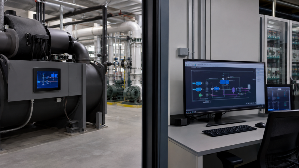
Eingebettete Kältemaschinen-HMI und eine separate entfernte Gebäudeautomations-Workstation
Definieren Sie, welche Informationen lokal verfügbar bleiben müssen, wenn das Gebäudenetzwerk nicht verfügbar ist. Entscheiden Sie umgekehrt, welche Funktionen auf die Steuerung oder das autorisierte entfernte System beschränkt bleiben sollten. Diese Entscheidungen gehören zur Kältemaschinen- und BAS-Architektur, nicht zum LCD-Modul.
Integrieren Sie die Anzeige für die Umgebung des Maschinenraums
Ein Panel, das auf einem offenen Entwicklungsprüfstand arbeitet, ist noch keine produktionsreife Kältemaschinen-HMI. Überprüfen Sie die Gehäuseöffnung, Sichtbarkeit der aktiven Fläche, Abdeckglas, Montagemethode, Steckerzugang, FPC-Biegeradius, Kabelzugentlastung, Spannungsentlastung, Servicefreiraum, Erdung, Abschirmung und Wärme von Display, Host, Stromumwandlung und angrenzenden Steuerungen.
Maschinenräume können ungleichmäßige Beleuchtung, reflektierende Metalloberflächen, Streiflicht bei flachem Winkel, Schmutz, Reinigungsaktivität, Feuchtigkeit und begrenzte Standpositionen kombinieren. Bewerten Sie die Lesbarkeit mit dem vorgesehenen Bildschirminhalt, Montagewinkel, Abdeckungsaufbau und repräsentativer Beleuchtung. Helligkeit allein begründet keine Lesbarkeit, da Oberflächenreflexionen, Kontrast, Betrachtungsrichtung, Abdeckmaterialien und GUI-Farben das Ergebnis ebenfalls beeinflussen.
Kondensations- und Feuchtigkeitsrisiken müssen durch das vollständige Gehäuse und die Installation adressiert werden. Ein abgedecktes oder touch-integriertes LCD begründet nicht automatisch eine Schutzart. Jede Aussage zu Abdichtung, Wasserbeständigkeit, Chemikalienbeständigkeit oder Umgebungsbedingungen muss sich auf eine definierte Baugruppe und eine anwendbare Validierung beziehen.
Motoren, Antriebe, Schütze, Stromversorgungen, Netzwerkverdrahtung, Sensoren und lange Kabelstrecken können eine elektrisch anspruchsvolle Umgebung schaffen. Display-Stabilität, Touch-Verhalten, Erdung, Kabelführung, EMV und Neustartverhalten müssen im produktionsnahen Schaltschrank bewertet werden. Das LCD-Modul allein kann keine Konformität für die vollständige Kältemaschine herstellen.
Machen Sie Anlauf, Datenalter und Kommunikationsverlust verständlich
Eine lokale HMI kann mit Strom versorgt bleiben, während die Kältemaschinensteuerung, das Kommunikations-Gateway oder die BAS-Verbindung nicht verfügbar ist. Die Anwendung sollte gespeicherte Daten nicht als aktuell darstellen. Definieren Sie, wie nicht verfügbare, verzögerte, ungültige oder teilweise aktualisierte Werte erscheinen und wie der Benutzer die Quelle und den Zeitstempel identifiziert, wo relevant.
Die Anlaufplanung sollte die Panel-Stromversorgung, Initialisierung der nativen Schnittstelle, Aktivierung der Hintergrundbeleuchtung, HMI-Host-Boot, Verfügbarkeit des Touch-Controllers, Anwendungsstart, Steuerungskommunikation und den Empfang gültiger Maschinendaten abdecken. Der Bediener sollte ein initialisierendes Display von einer betriebenen Kältemaschine unterscheiden können.
Testen Sie.
Repeated power cycling, incomplete startup, application restart, controller restart, touch recovery, and restoration of the correct equipment context should be included in system testing.
Validieren Sie die produktionsrelevante HMI-Baugruppe
Validation should progress from electrical bring-up to the selected display, touch stack, HMI host, active bridge where used, cables, power supply, enclosure, application, controller communication, and intended chiller environment.
Verwenden Sie repräsentative Bediener- und Service-Workflows. Prüfen Sie Geräteübersicht, Berechtigungen, Alarme, Langmeldungen, Trends wo erforderlich, Kommunikationsstatus, nicht verfügbare Daten, Hochlauf, Neustart, Stromunterbrechung und Wiederherstellung. Bewerten Sie die Lesbarkeit bei der erwarteten Montagehöhe und Blickpositionen, und testen Sie die Touch-Funktion mit den vorgesehenen Handschuhen, Feuchtigkeitsbedingungen, Abdeckungskonstruktion und Erdung.
Die mechanische Validierung sollte Toleranzen, Ausrichtung der Abdeckung, Sichtbarkeit des aktiven Bereichs, Haltekraft der Steckverbinder, FPC-Führung, Schranktürbewegung sofern zutreffend, Zugentlastung, thermische Bedingungen und den Austausch im Servicefall umfassen. Wenn das Design einen aktiven Display-Controller verwendet, schließen Sie dessen Firmware, Startverhalten, Grafikverarbeitung, Stromversorgung, thermische Last, EMV-Beitrag und Verfügbarkeit in denselben Plan ein.
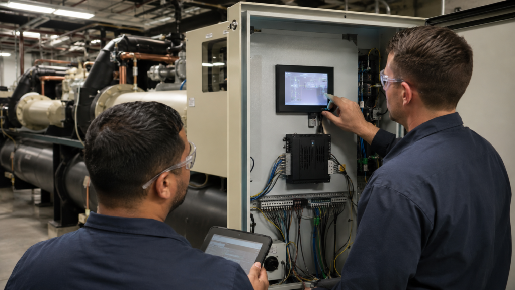
Produktionsnahes Chiller-TFT-HMI, das einer optischen, Touch-, Kabel-, Schrank- und Kommunikationsvalidierung unterzogen wird.
Definieren Sie messbare Abnahmekriterien vor dem Design-Freeze. Begriffe wie “Handschuhbedienung”, “wassergeschützt”, “hohe Lesbarkeit”, “Echtzeit” oder “Industriequalität” sind unvollständig ohne definierte Umgebung, Inhalte, Benutzerbedingungen, Systemgrenzen, Testmethode und gefordertes Ergebnis.
Erstellen Sie eine aussagekräftige Anforderungsspezifikation für das Kältemaschinen-Display
Geben Sie den Ziel-Aktivbereich, die Gehäusezeichnung, Montageposition, Ausrichtung, repräsentative GUI, Betrachtungsabstand, Host-Prozessor oder Rechenboard, verfügbare native Display-Ausgänge, Betriebssystem, Touch- und Abdeckungsanforderungen, Handschuh- und Reinigungsbedingungen, erwartete Feuchtigkeitseinwirkung, Kabelspezifikationen, Einschaltsequenz, Projektphase und den erwarteten Bedarfsumfang an.
Identifizieren Sie die angeforderte Liefergrenze: ein rohes TFT-LCD-Modul, eine LCD- und Touch-Baugruppe, eine abgedeckte Display-Baugruppe, ein LCD mit aktivem Video-Controller, eine eingebettete Rechenplattform oder ein vollständigeres HMI-Subsystem. Dies sind unterschiedliche Produkte und erfordern unterschiedliche Kompatibilitäts-, Firmware-, mechanische und Softwareinformationen.
RJY Display kann bestehende geeignete Display-Plattformen und projektspezifische Anpassungen prüfen, die Touch, Abdeckungskonstruktion, Hintergrundbeleuchtung, FPC, Schnittstelle, Controller-Board und mechanische Koordination umfassen. Die Machbarkeit hängt von der ausgewählten Plattform und den bestätigten Anforderungen ab. Dies bedeutet nicht, dass eine beliebige neue LCD-Zellengröße aus dem Nichts erstellt werden kann oder dass RJY das gesamte Kühlsystem, die Steuerung, das BAS oder das Sicherheitssystem qualifiziert.
Ist ein TFT-LCD dasselbe wie eine Kühlersteuerung oder ein vollständiges HMI?
Nein. Das TFT-LCD stellt Pixel dar. Ein vollständiges HMI erfordert zusätzlich einen Host, Anwendungssoftware, Eingabegeräte, Stromversorgung, Kommunikation, mechanische Integration und eine definierte Interaktion mit der Kühlersteuerung.
Kann BACnet ein TFT-LCD direkt ansteuern?
Nein. BACnet überträgt Gebäudeautomatisierungsdaten, keine nativen LCD-Pixelsignale. Ein Controller, Gateway oder HMI-Host muss die zulässigen Daten abrufen, die Oberfläche rendern und das TFT über einen kompatiblen Display-Pfad ansteuern.
Can HDMI directly drive a raw MIPI, RGB, LVDS, or eDP panel?
Nein. Ein passives Kabel kann HDMI nicht in eine rohe MIPI-, RGB-, LVDS- oder eDP-Panel-Schnittstelle umwandeln. Ein kompatibler aktiver Controller oder eine Brücke ist erforderlich und muss die Quelle und die genauen Panel-Anforderungen unterstützen.
Is the touchscreen connection the same as the LCD video interface?
No. The video interface sends pixel data to the LCD. Touch normally uses a separate sensor, controller, connection, firmware configuration, and software input path.
Was sollte ein Kühler-OEM für eine Display-Überprüfung bereitstellen?
Stellen Sie das Gehäuse und den Ziel-Aktivbereich, die repräsentative GUI, Montage- und Betrachtungsbedingungen, die Host-Plattform, native Display-Ausgänge, das Betriebssystem, Touch- und Abdeckungsanforderungen, Handschuh-, Feuchtigkeits- und Reinigungsbedingungen, Kabel- und Stromversorgungsbeschränkungen, die Projektphase und den erwarteten Bedarfsumfang bereit.