Understanding the Power Domains of a TFT LCD
A typical TFT LCD module requires:
- Logic Power (VCC) — usually 3.3 V or occasionally 5 V, powering the internal controller and data interface.
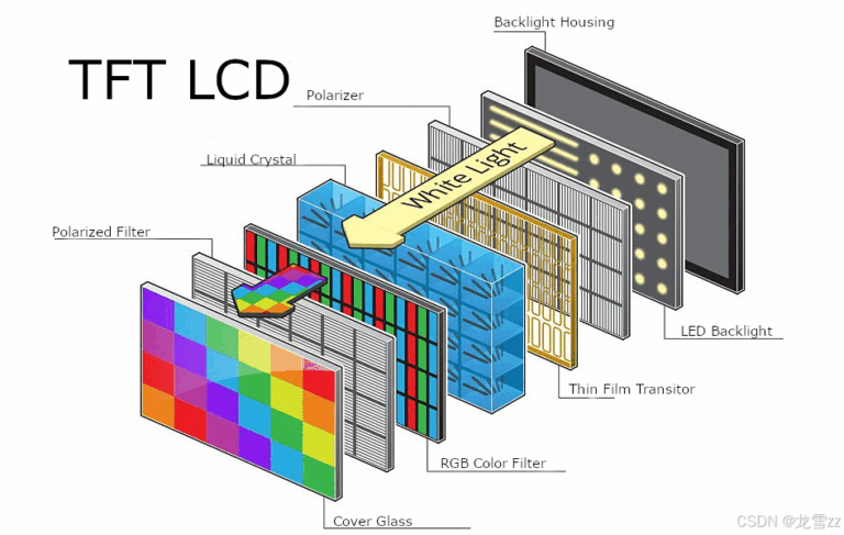
- Backlight Power — LEDs often need higher voltage (e.g., 12 V or more in series), whereas traditional CCFLs require an inverter.
- Bias Voltages for Advanced Panels — some automotive or industrial TFTs require AVDD, VGH/VGL, VCOM rails generated by charge-pump circuits.
Backlight: The Major Power Draw
The backlight is often the TFT’s most power-hungry element.
- LED backlights typically need 30–80 mA, depending on brightness and module design.
- Adjusting brightness is usually done via PWM control, often routed through a MOSFET driver or internal regulator.
Conseil : If driving series LEDs, a constant-current driver or MOSFET is ideal; otherwise use a current-limiting resistor (~18 Ω) to protect both the LEDs and driver.
Logic Voltage: The Essential Rail
Logic voltage powers the TFT controller:
- Commonly 3.3 V, though older modules may use 5 V.
- Ensure the MCU’s logic levels (e.g., SPI or parallel interface) match the display’s requirement—or use level shifters if needed.
Backlighting and logic can share input power, but it’s safer to separate them for stability and reduce noise.
Managing Multiple Voltage Rails
Advanced TFT panels may require multiple bias voltages, including AVDD, VGH/VGL, and VCOM, often in the range of ±6V to ±24V. These are typically generated by dedicated driver ICs such as the TPS65150 series to ensure precision and proper sequencing.
Power Sequencing: Order Matters
Correct turn-on/off sequence prevents damage or visual artifacts:
- Power the logic rail (VCC) first.
- Stabilize the panel.
- Enable backlight last.
- During shutdown, reverse the order—turn off backlight first.
Manufacturer datasheets may specify precise timings.
Practical Example Scenarios
A. Basic TFT with LED Backlight (Arduino/ESP):
- Logic: 3.3 V regulated for the controller
- Backlight: 12 V or higher through MOSFET and PWM for brightness control
B. Battery-Powered Display:
- Use a DC‑DC converter to generate regulated 3.3 V logic and boost 5–12 V for the backlight.
C. Automotive or Industrial Panel:
- Input from 12–18 V (vehicle battery range)
- Use robust step-down and charge-pump drivers for logic and bias rails to meet stringent sequencing and voltage requirements.
Wiring Best Practices
- Use decoupling capacitors (0.1 µF + 10 µF) close to power pins for stability.
- Isolate ground paths—separate logic and backlight grounds and merge them at a single point.
- Add a reverse polarity diode and EMI filters to protect module integrity.
Questions fréquemment posées
Q: Can I use a single 3.3V supply for both logic and backlight?
A : Only if the module includes an integrated constant-current or backlight driver—otherwise a separate high-voltage source or driver is needed.
Q: Why do some TFTs need 12V backlight when the panel runs on 3.3V?
A : Because the LEDs are arranged in series and require higher voltage to reach the desired current levels efficiently.
Q: Are charge pumps essential for all TFTs?
A : Not always; only advanced or high-voltage panels requiring multiple bias rails need charge-pump circuits.
Final Recommendations
- Start by reading the TFT’s datasheet—pinouts, power requirements, and sequence are usually specified.
- Design proper power rails: separate logic and backlight, use regulators and MOSFETs when necessary.
- Follow proper sequencing and grounding practices to ensure display reliability and longevity.


