組込み表示プロジェクトでボトルネックに直面していませんか?
複雑な統合作業やサプライチェーンの問題が市場投入までの時間を遅らせないようにしましょう。RJYの専門家チームによる無料コンサルテーションを予約し、お客様に合わせた設計・製造サポートをご利用ください。.

A TFT LCD datasheet may describe the display mode as normally black または normally white. These terms sound simple, but they are frequently misunderstood. Some buyers assume they describe the color of an unpowered module. Others interpret normally black as a guarantee of better contrast or normally white as a sign of older technology.
Neither assumption is reliable by itself.
Normally black and normally white describe how the LCD optical system controls light in its reference or non-activated state. The behavior is determined by the liquid-crystal arrangement, polarizers, electrode structure and driving method. It does not describe the entire performance of the finished display.
Understanding the distinction helps engineers interpret datasheets, compare candidate TFT modules and diagnose what happens during startup, signal loss or abnormal operation.
A liquid-crystal display does not produce light at each pixel. In a transmissive TFT LCD, the backlight produces light and the LCD stack controls how much of that light reaches the viewer.
The liquid-crystal layer sits between polarizing elements. Changing the electrical state of a pixel changes how light passes through this optical system.
In a normally black mode, the reference optical state blocks most of the transmitted light. Applying the intended pixel drive changes the liquid-crystal orientation so that controlled amounts of light can pass through.
The term “normally black” therefore refers to a dark reference state—not to the black color of the cover glass, bezel or entire unpowered module.
In a normally white mode, the reference optical state allows more light to pass. The applied pixel drive changes the liquid-crystal orientation to reduce transmission and create darker gray levels.
“White” in this term means a light-transmitting state when the backlight and optical system are operating. It does not mean the module will emit white light after all electrical power has been removed.
The words “normally black” and “normally white” are sometimes interpreted as instructions for a simple power-off test. In practice, the appearance of an unpowered module can be more complicated.
When equipment is fully powered off, its backlight is normally off as well. Without illumination from the backlight, the viewer may see reflections from the polarizers, cover glass and internal optical layers rather than the intended transmissive state.
The visible appearance may be:
Residual charge and the exact power-down sequence can also affect the pixels briefly after power is removed. Therefore, the display mode should be confirmed from the panel specification rather than judged only by looking at an unconnected LCD.
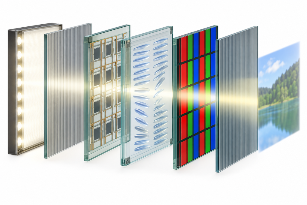
A simplified transmissive TFT LCD includes:
The two polarizers and liquid-crystal layer work together as an optical valve. The TFT circuit controls the voltage associated with each subpixel, while the liquid crystals modify the polarization state of light. The front polarizer then transmits or blocks part of that light.
Red, green and blue color filters form the visible color image. Gray levels are produced by controlling light transmission through the subpixels, not simply by switching every pixel completely on or off.
The word “normally” describes the reference behavior of the electro-optical mode. During ordinary operation, an active-matrix display continually refreshes pixel voltages. The visible black and white portions of the user interface are therefore driven image states.
This distinction matters when diagnosing a screen that becomes light, dark or irregular during startup. The observed state may be affected by the controller, initialization sequence, data enable, timing, power rails and backlight—not only by whether the panel is classified as normally black or normally white.
| Comparison | 通常は黒 | Normally white |
|---|---|---|
| Reference optical state | Primarily light-blocking | Primarily light-transmitting |
| Light-state creation | Pixel drive increases controlled transmission | Reference state already transmits more light |
| Dark-state creation | Associated with the reference optical state | Pixel drive reduces light transmission |
| Appearance without backlight | Not necessarily ideal black | Not necessarily visible white |
| Display-quality conclusion | Cannot be determined from mode alone | Cannot be determined from mode alone |
Normally black configurations are often associated with a darker reference state. However, the black appearance of a finished display also depends on the LCD technology, polarizer efficiency, cell design, backlight leakage, viewing angle, optical bonding and ambient reflections.
A normally black label does not guarantee perfect black. Transmissive TFT LCDs use a backlight, and some light leakage may remain in dark image areas.
Likewise, a normally white display should not automatically be considered low quality. It may be suitable for an application when its complete optical performance, viewing characteristics, cost and operating conditions meet the product requirements.
TN, or twisted nematic, LCDs are commonly encountered in normally white configurations. In a simplified normally white TN cell, the liquid-crystal twist changes the polarization of light in the reference state, allowing it to pass through the front polarizer. Applying a voltage reduces that twist and changes transmission.
However, TN technology and normally white operation are not identical definitions. TN describes the liquid-crystal mode, while normally white describes the electro-optical state. The actual display mode must be confirmed from the specific panel documentation.
It is safer to say:
IPS-family and VA-family LCDs are commonly associated with normally black operation. Their liquid-crystal structures differ from the conventional TN arrangement, and many implementations use a dark reference state.
Once again, the technology name should not replace the datasheet. IPS, VA and related commercial terms cover multiple implementations. A buyer should confirm the exact module’s display mode, viewing characteristics and optical specifications.
IPS is often selected when an application requires more consistent appearance across wider viewing positions, but the words “IPS” and “normally black” do not by themselves confirm brightness, contrast, color gamut, response time or outdoor readability.
Not automatically. Contrast is a relationship between the luminance of bright and dark image states under defined measurement conditions. Normally black operation can support a dark reference state, but the finished result depends on more than the reference mode.
Factors affecting perceived contrast include:
A panel with strong laboratory contrast may still look washed out behind reflective cover glass in a bright room. Conversely, suitable optical integration can improve the perceived result without changing the normally black or normally white classification.
The display mode can influence how dark and light states behave at different angles, but viewing angle depends on the complete LCD architecture.
A normally white TN display may exhibit contrast inversion or color changes when viewed from an unfavorable direction. For this reason, TN datasheets often specify a preferred viewing direction.
A normally black IPS-family display may maintain a more consistent image across a wider set of positions, but it can still exhibit brightness or color changes at oblique angles. Cover glass, bonding and reflections also influence what users actually see.
When selecting a display, engineers should define:
Physical samples should be evaluated from the real operating positions. A display-mode label cannot replace this test.
Product teams sometimes select a normally black display because they expect the screen to remain dark whenever the host is inactive. The actual startup appearance depends on the complete system sequence.
A TFT LCD module can involve several separately controlled functions:
If the backlight turns on before valid image data and correct panel initialization are established, the user may see a gray, white, dark or unstable intermediate state. This should not automatically be interpreted as evidence that the panel was incorrectly specified.
Similarly, loss of the video signal does not necessarily return every TFT LCD to its reference optical state in a controlled way. The display may retain its last frame briefly, show an undefined pattern or behave according to its timing controller and system design.
Equipment that requires a controlled startup appearance should manage the backlight, reset, display initialization and image source as one sequence.
For safety-related or highly controlled equipment, it is risky to assume that a normally black LCD will always become black after every system fault.
A fault can affect only part of the system. For example:
If a specific failure appearance is required, it must be designed and validated at the system level. The normally black classification alone is not a safety mechanism or failure-state guarantee.
The normal mode is part of the LCD optical design. It is not normally changed through a menu setting, firmware command or simple inversion of the image data.
Software can invert displayed colors, turning white user-interface regions black and black regions white. This changes the content, not the underlying electro-optical mode.
Changing polarizer orientation or replacing optical layers is also not a practical field conversion. Polarizers are selected and laminated as part of the panel design. Modifying them can affect contrast, color, viewing behavior, durability and manufacturing yield.
If the project requires a different normal mode, the appropriate path is to evaluate another LCD module or discuss a feasible display configuration based on an existing platform.
Look for fields such as display mode, LCD mode, normally black, normally white, transmissive type, TN, IPS or VA. Do not rely only on the seller’s product title.
The LCD mode is an optical property of the panel. The controller board supplies the signals and sequencing required for operation. A board cannot convert the physical liquid-crystal mode through software alone.
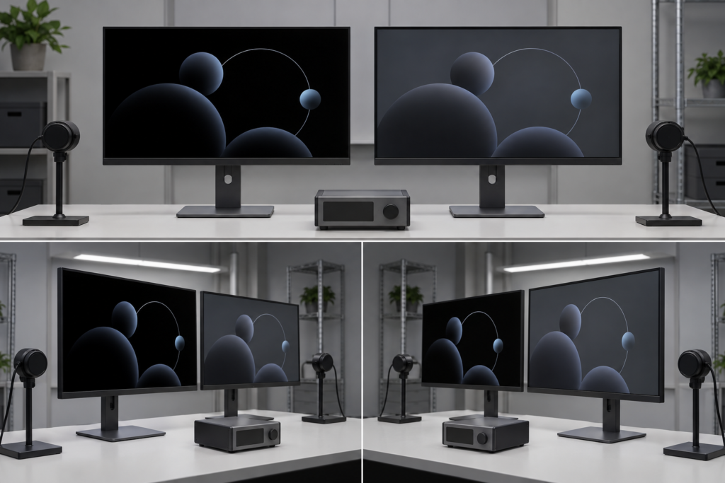
Compare black, white, gray and color patterns from the intended viewing positions. Keep the content, backlight setting and ambient lighting consistent when comparing samples.
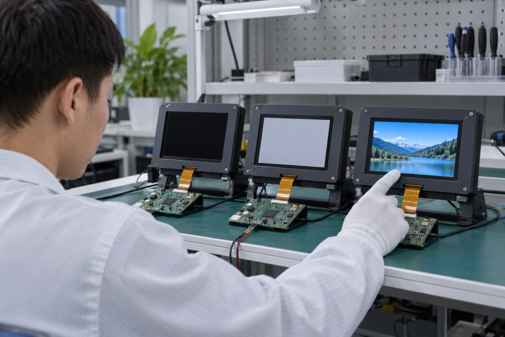
Record when logic power, image data and the backlight become active. If an unwanted flash appears, investigate sequencing and firmware before assuming that changing the LCD mode will solve the problem.
Cover glass, touch layers, bonding, bezel pressure and enclosure reflections can change the perceived image. Complete the final evaluation with the display installed in a representative enclosure.
The correct choice depends on the application rather than a universal ranking.
A dark user interface may benefit from a display with a strong dark-state appearance, especially when large black areas remain visible. A predominantly light interface may place greater emphasis on white uniformity, brightness and power requirements.
Industrial panels mounted below eye level, handheld devices, wall controls and central tabletop products have different viewing requirements. The LCD mode should be considered together with the panel technology and specified viewing direction.
If a product must avoid a bright flash at startup, the engineering team should examine both the panel and the backlight-control sequence. Selecting normally black may help define the intended optical state, but system sequencing still requires validation.
A capacitive touchscreen, thick cover glass, anti-glare treatment or air gap may affect perceived black level and reflection. Compare the complete assembly rather than making the decision from a bare LCD sample.
Display mode is only one line in a datasheet. The selected module must also satisfy the required size, resolution, interface, pin definition, brightness, viewing characteristics, backlight, touch, temperature and mechanical constraints.
For a project-specific TFT LCD review, prepare:
Normally black and normally white explain the reference optical state of an LCD. They do not, on their own, determine contrast, viewing angle, image quality, startup behavior or application suitability.
A useful selection process considers the LCD mode together with panel technology, optical performance, viewing position, backlight, cover glass, touch integration, controller timing and enclosure conditions.
If you are comparing TFT LCD modules for an embedded product, explore RJYカスタムディスプレイソリューション または RJYにお問い合わせください with the panel, host and mechanical requirements for an engineering review.
A normally black LCD uses a primarily light-blocking reference optical state. Applying the intended pixel drive controls how much light passes through the LCD. The term does not guarantee perfect black or define the appearance of the complete unpowered module.
A normally white LCD uses a primarily light-transmitting reference optical state. Pixel drive is used to reduce transmission and create darker levels. It does not mean the screen produces white light without an operating backlight.
No. Suitability depends on panel technology, contrast, viewing direction, brightness, interface design, optical integration and operating conditions. The display should be evaluated against the complete product requirements.
Many TN LCDs use normally white operation, but the terms are not interchangeable. TN describes a liquid-crystal mode, while normally white describes an electro-optical state. Confirm the actual mode from the panel datasheet.
No. Software can invert the colors of the displayed content, but it does not change the underlying liquid-crystal mode or polarizer configuration.
ディスプレイサイズ、解像度、インターフェース、輝度、タッチ要件、コントローラーボード要件、およびアプリケーション環境を共有してください。.
関連するディスプレイ技術ガイドとアプリケーションリファレンスを引き続きお読みください。.
RJYのエンジニアリングチームにご相談いただき、ディスプレイマッチング、コントローラーボードの確認、およびカスタマイズについて話し合ってください。.