As of October 26, 2026, OLED-on-silicon developments give near-eye designers more architectures to evaluate, not a single specification to rank. Recent announcements span high-voltage backplanes, direct RGB demonstrations, and RGBW research with different driving modes. These developments concern different design choices; they are not three mutually exclusive architectures.
A higher pixels-per-inch figure does not establish how much detail the user sees through an optical system. A peak luminance figure does not establish the brightness available at the eye during sustained use. For product planning, connect each component claim to the intended field of view, content, optical path, and operating conditions.
This analysis concerns silicon OLED microdisplays, often called OLEDoS or micro-OLED. It focuses on near-eye component and system trade-offs. It does not assume that an exhibition device, a research platform, and a catalog component have the same commercial status.
What changed in the 2026 evidence
Three dated announcements illustrate the range of development. The organizations’ claims below remain attributed statements. The implications in the final column are our analysis of what an engineering team still needs to establish.
| Date and source | Reported development | Planning implication and limit |
|---|---|---|
| April 21, 2026 — Fraunhofer IPMS | The institute announced initial results for a 2K OLED microdisplay using its high-voltage backplane concept, with evaluation kits available.1 | This creates an evaluation path for a specific design. Initial results and kits do not establish routine volume supply or performance in another optical assembly. |
| June 17, 2026 — Samsung Display | The manufacturer announced RGB OLEDoS demonstrations at AWE USA, including a panel described as reaching 40,000 nits and prototype smart glasses.2 | The luminance is a vendor claim in an exhibition panel context. It is not an at-eye measurement, a sustained operating guarantee, or proof of long-term availability. |
| September 21, 2026 — Fraunhofer IPMS | The institute reported an RGBW microdisplay on a 28 nm CMOS process, with frame-based and memory-based driving concepts.5 | The research makes content and drive strategy relevant comparison points. It does not establish a universal power advantage or an interchangeable commercial product. |
Sony’s current OLED microdisplay catalog provides a separate reference: it lists models with different applications, interfaces, luminance conditions, and availability status.3 This is a current product listing, not another new 2026 announcement. A listed status also does not replace confirmation of the exact model and project terms.
Together, these sources suggest a more useful market question than “Who has the largest number?” Which architecture and drive strategy can deliver the required image through the intended optics, with the available power and thermal budget?
Compare color architectures against the content
Sony describes a top-emission structure using white emission and color filters on a silicon backplane.3 That is a different color implementation from direct RGB emission. An RGBW pixel arrangement adds a white channel to the color channels. It describes the channel layout, while white emission with filters and direct RGB describe how color is produced. Establish both for each candidate instead of treating the labels as mutually exclusive options.
Fraunhofer’s September design includes a backplane block that calculates the white subpixel from RGB input. Its announcement links frame-based operation to continuous updates and memory-based operation to static content.5 Treat those as features of the reported implementation. Do not assume that every RGBW display uses the same conversion or drive behavior.
Build a comparison around actual images. A mostly white information overlay, saturated symbols, small colored text, and full-motion video exercise different combinations of channels and updates. Request measurements using those patterns at the required apparent size and image quality.
For example, a white-heavy interface may make the white channel worth investigating. That does not establish an advantage for saturated content. Likewise, a direct RGB demonstration may justify evaluation without proving better power, color accuracy, or lifetime in the intended enclosure. Keep the measured result attached to the architecture, operating point, and content that produced it.
Separate pixel density from the image seen by the eye
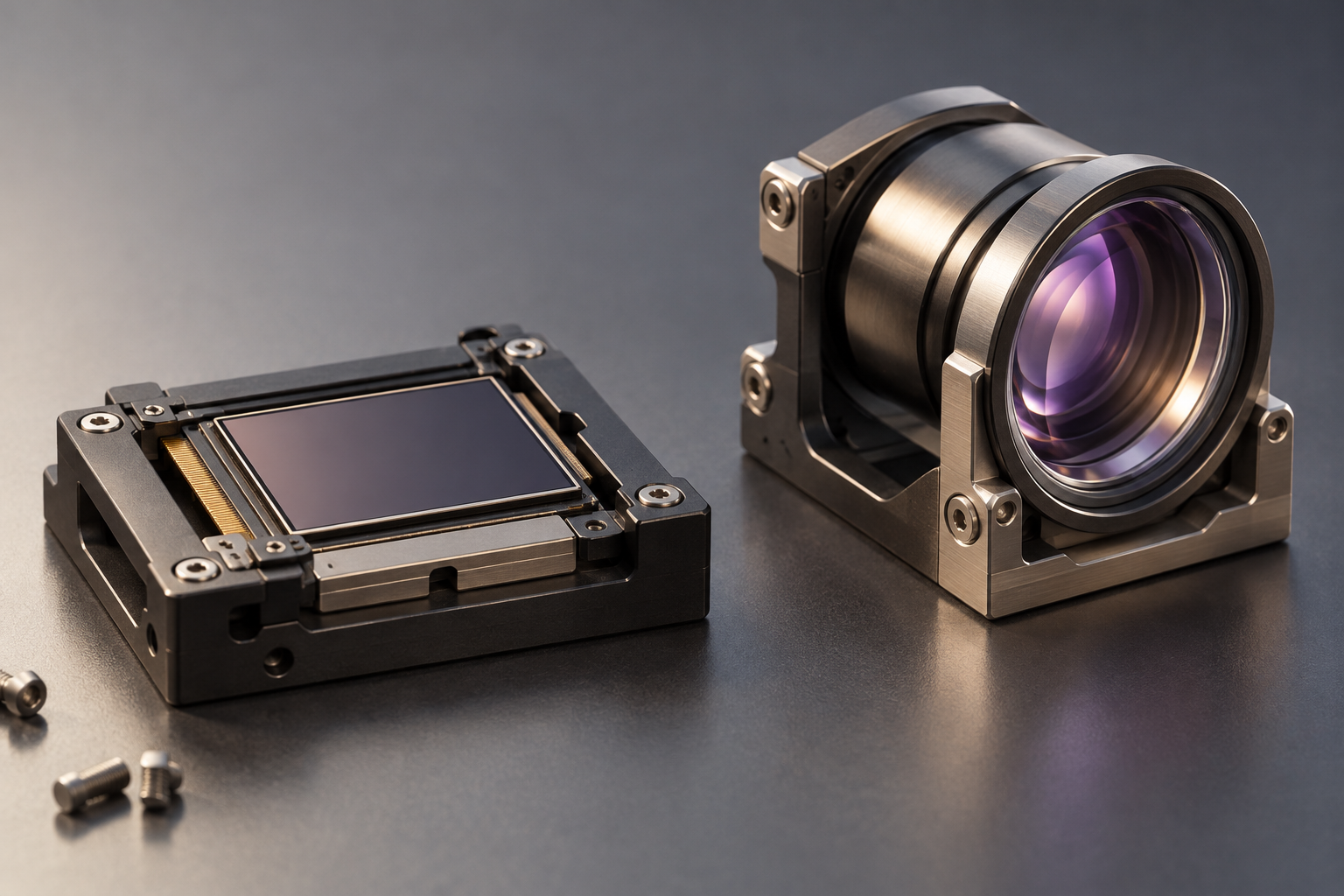
PPI describes physical pixel density. Addressable image dimensions give the pixel count along each axis; total pixel count gives the number of image pixels. Subpixel pitch describes spacing within a specified arrangement. Pixels per degree (PPD) describes angular pixel sampling under a defined image mapping. It does not establish the detail that the optics actually resolve. These quantities answer different questions.
The September Fraunhofer announcement offers a useful example. It reports 720 × 540 pixels, up to 5,040 PPI, and a 2.52 × 2.52 micrometer subpixel size.5 Keep those figures attributed to the research announcement. The subpixel dimension must not be relabeled as full-pixel pitch. The density claim also does not change the stated image dimensions.
For an OEM comparison, first establish the active image, full-pixel structure, and usable pixel count. Then define the intended field of view and where fine detail must remain readable. A display used for a compact information window faces a different task from one spread across a broad visual field.
Test the optical result with text, line patterns, and edge targets at relevant locations. Record the image mapping and any cropping or resampling. A center image can look sharp while detail elsewhere fails the requirement. Panel PPI alone cannot resolve that question, and increasing it cannot prove that the optics preserve the extra detail.
Keep panel luminance and at-eye measurements separate
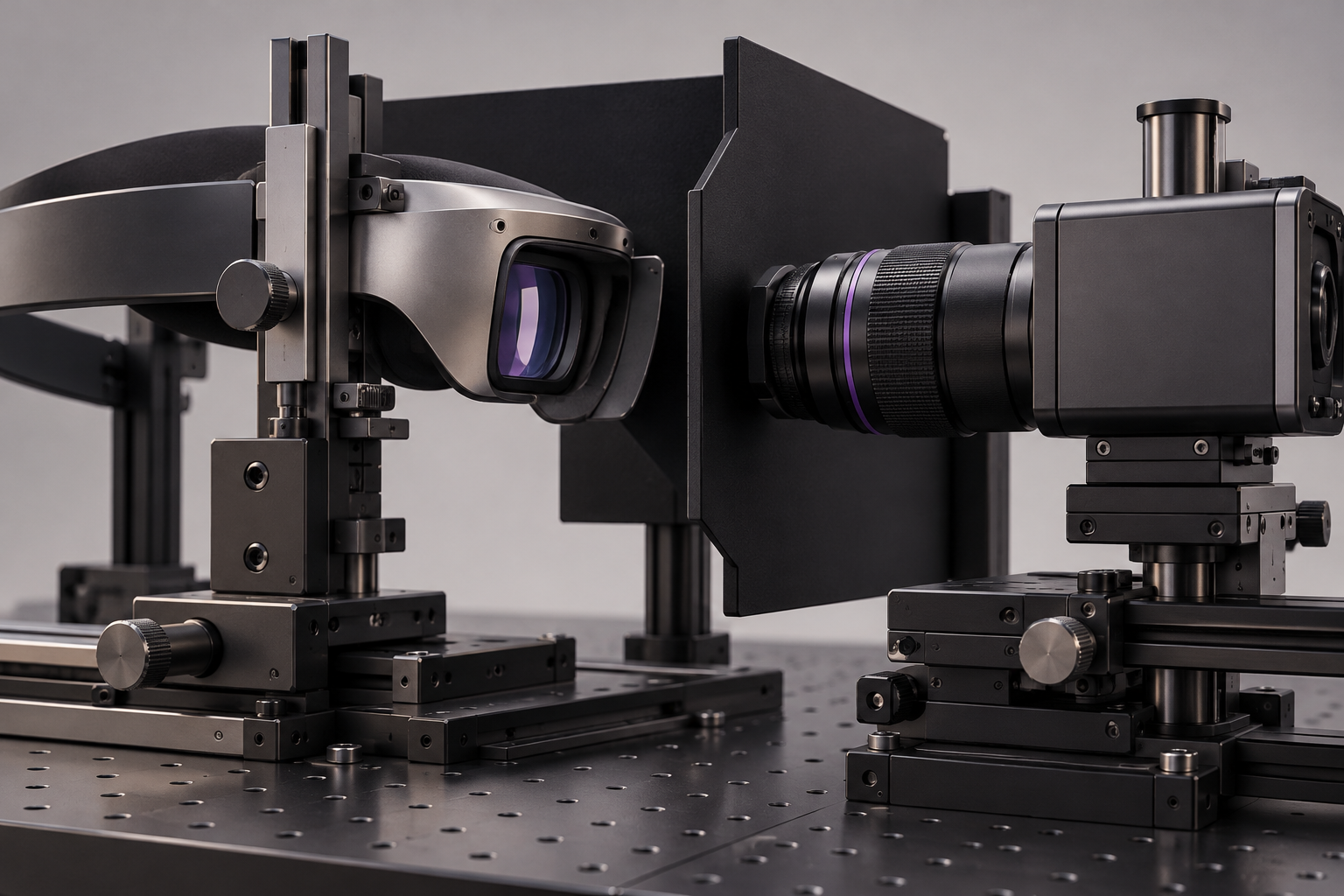
A panel specification describes a component under stated conditions. A near-eye assembly adds an optical path and a defined viewing position. Do not compare a bare-panel luminance figure directly with a result measured through a headset, or apply one assumed transmission percentage to every design.
Radiant Vision Systems describes near-eye measurement with the instrument’s entrance pupil placed at the eye location. Its AR/VR measurement offering includes luminance, chromaticity, contrast, modulation transfer function (MTF), and distortion analysis.4 MTF characterizes how well the system preserves contrast at different spatial detail levels.
The following comparison method is our proposed engineering approach, not a requirement set by the measurement supplier. Fix the optical assembly, eye relief, measurement aperture, and pupil position. Select measurement positions across the intended eye box, the region in which the design is intended to provide a usable image. Define the usable-image criteria for this project. Keep the test pattern, drive settings, and ambient conditions with the results.
For an overlay application, include the background conditions under which information must remain legible. For an enclosed viewing system, include image uniformity, dark content, and the required field. An eye-center reading alone may miss position-dependent behavior. Compare candidates under the same task and measurement geometry before interpreting a brightness difference.
Attach brightness to duty, drive, power, and time
Sony’s lineup pairs maximum luminance with duty ratio and lists model-specific video interfaces.3 Preserve those conditions when using a catalog value. Do not borrow a brightness figure from one model and an interface or operating mode from another.
Define what “peak” means in the proposed test: pattern area, channel values, emission duty, refresh rate, temperature, and duration. Record whether output remains at the reported level after warm-up and throughout the intended session. A brief bright pattern and a sustained information screen are different workloads even when their highest pixel value matches.
Measure power at a stated boundary. Panel-only power excludes some of the electronics that a finished device must support. Record the included driver, power conversion, and host activity rather than comparing figures with different boundaries. Use the same content sequence and update policy for each candidate.
Ask for lifetime evidence at the proposed operating point, including the failure or degradation criterion. A claim without temperature, luminance history, duty, and content conditions cannot establish the required service behavior. This is also why a demonstration brightness should not become a lifetime design target without supporting data.
Treat host integration as part of the optical workload
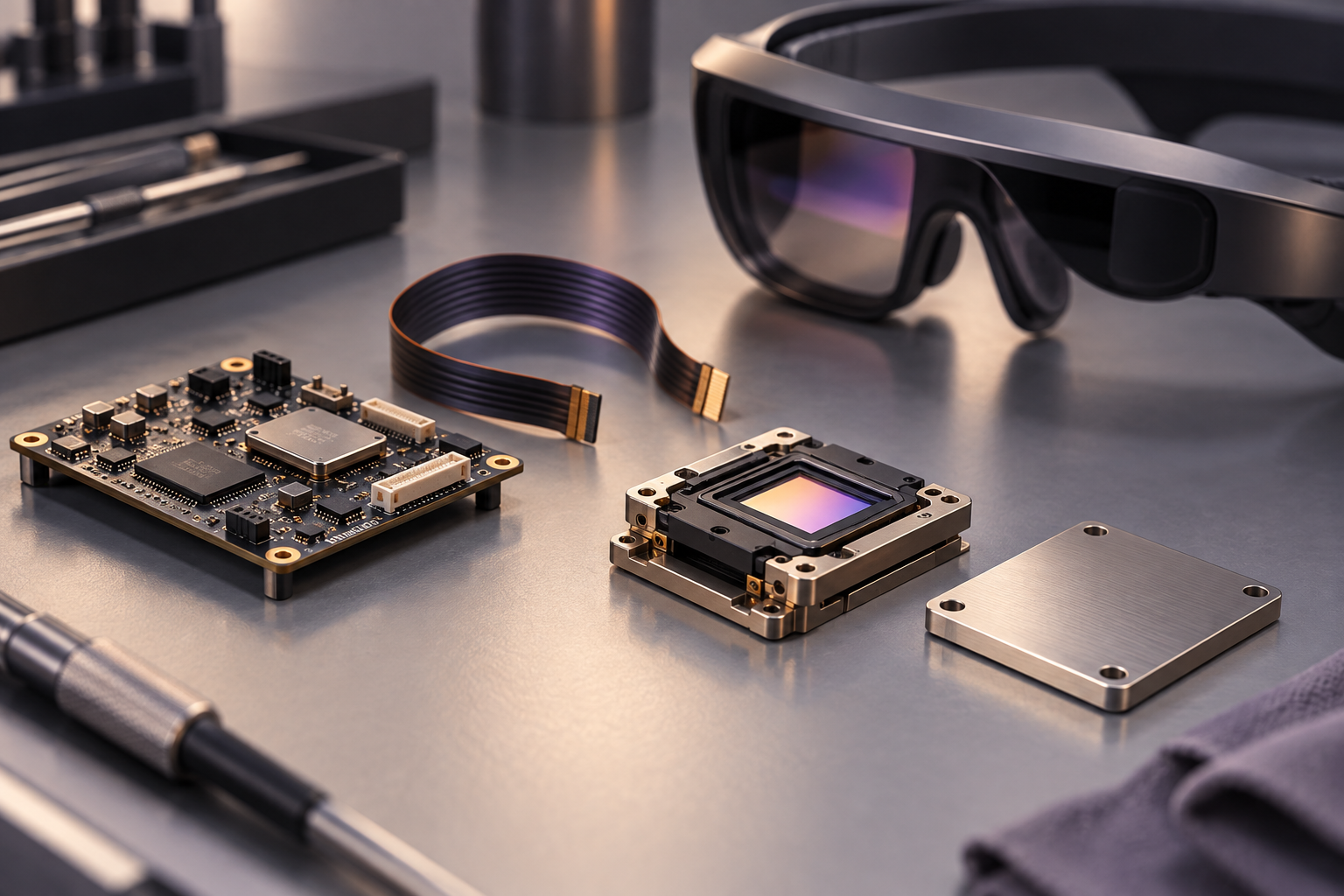
Fraunhofer’s April platform combines an on-chip LVDS interface with a module power concept, according to the institute.1 It illustrates how integration details can change alongside the emitter and backplane. The exact component documentation must define what the host actually supplies.
For each candidate, map the required image dimensions, frame timing, input encoding, and supported drive modes to the host. Establish whether the application can use a static-content mode, what updates it still requires, and what happens when content changes. A mode that looks attractive for a stationary symbol may offer less benefit during frequent redraws.
Replay a representative session rather than one still image. Include transitions between sparse overlays, dense text, and motion where applicable. Log the host state, display settings, power, and temperature together. This makes it possible to identify whether a benefit comes from the panel, reduced update activity, or a different workload.
A conditional outlook for 2027–2028
The following is original conditional analysis, not a shipment, share, or product-release forecast. Our reading of the 2026 evidence favors separate use-case comparisons over a claim that one architecture will dominate all near-eye displays.
Sparse overlays may favor content-aware drive choices
If static or slowly changing information occupies much of a product’s use time, memory-oriented driving and color-channel strategy could become stronger selection factors. Supporting evidence would be lower measured session energy at the required image quality and brightness. Frequent updates that remove the benefit, or added host activity that offsets it, would weaken this scenario.
Bright-background overlays may prioritize useful optical output
If a design must preserve readable information against demanding backgrounds, higher panel output could expand the evaluation options. This scenario strengthens when a complete optical assembly meets contrast and pupil-position requirements within its thermal budget. It weakens when the extra panel output fails to improve the usable image or cannot be sustained under the intended conditions.
Broad-field viewing may reward balanced spatial performance
If a product spreads detailed content across a broad field, total usable pixels, optical detail transfer, and host capability could matter more than the highest PPI label. Evidence would include readable targets across the required field during representative motion. A dense panel that loses detail through the selected optics would argue against ranking density first.
These paths can develop at different speeds. Update the comparison when a new architecture offers measured benefits for the actual use case. A stronger headline specification alone is insufficient reason to change a design assumption.
Keep conventional TFT projects on their own requirements path
A direct-view TFT HMI has a different viewing geometry and integration task. For that work, review LCD module interface options e standard display candidates against the host and mechanical requirements.
Contact RJY Display about an existing TFT LCD requirement or project-dependent adaptation. This inquiry path concerns LCD projects; it does not imply that RJY supplies micro-OLED devices or has a relationship with the organizations cited here.
Referências
- Fraunhofer IPMS: Innovative 2K OLED microdisplay for near-eye applications, April 21, 2026.
- Samsung Display: Samsung Display Sets Sights on Next-Gen XR Innovations at AWE USA, June 17, 2026.
- Sony Semiconductor Solutions: OLED Microdisplay, current catalog accessed October 26, 2026.
- Radiant Vision Systems: AR/VR Lens, accessed October 26, 2026.
- Fraunhofer IPMS: Full-Color RGBW Microdisplays: Next Generation for Brilliant, Energy-Efficient Visualization, September 21, 2026.