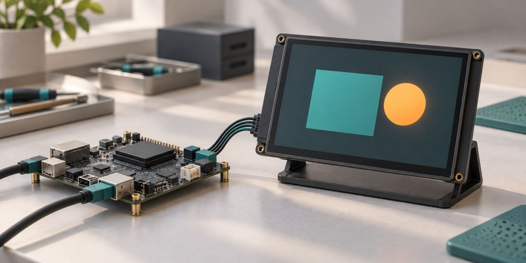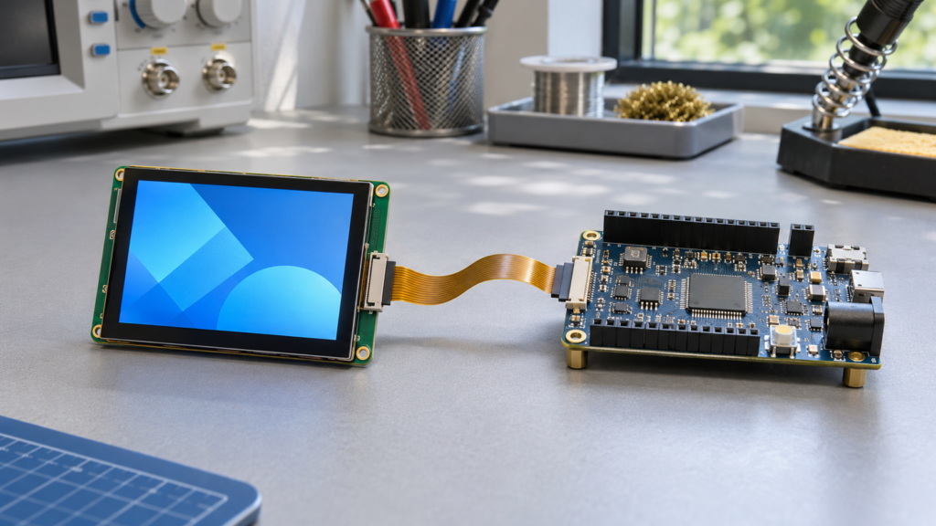
An I²C touchscreen that works on a short bench setup can fail after installation because the complete product changes the electrical and software conditions. A longer cable, an additional device on the bus, a different power sequence, or a missing host configuration may stop touch reports even while the LCD image looks normal.
Start by treating the display and touch interfaces as separate paths. A working image establishes that the display path is operating; it does not prove that the touch controller is powered, communicating, or supported by the host. RJY’s TFT LCD touch-module guide explains the wider integration requirements.
What changes when the screen is installed?
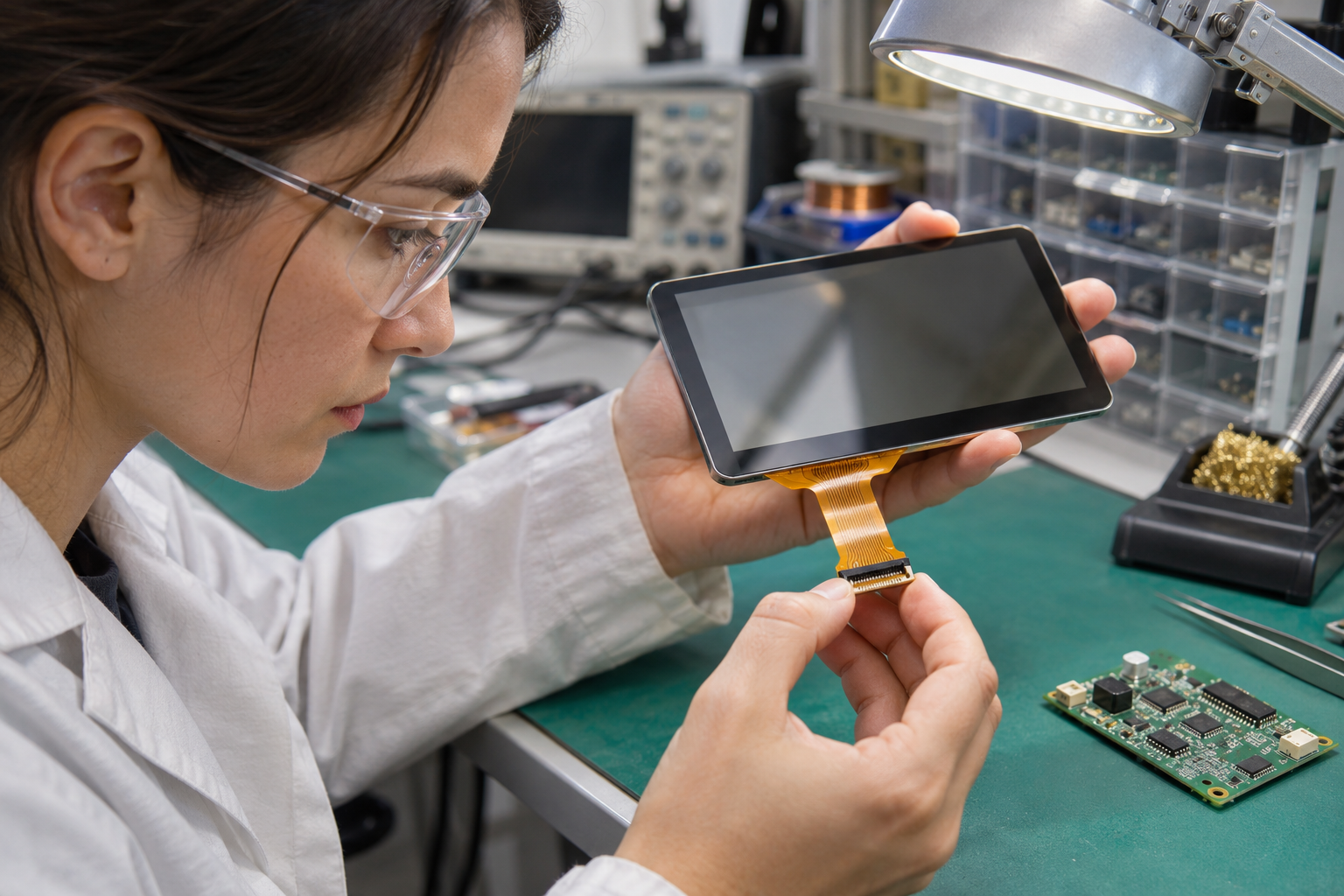
The production enclosure can introduce a longer flex cable, extra connectors, another I²C device, a different ground return, or noise from nearby electronics. The target board may also use different supply rails and startup timing from the evaluation board. Any one of these changes can reduce communication margin or expose an incorrect assumption about the touch controller.
Record the panel and touch-controller model, host board, cable, firmware, operating system, and the exact conditions in which touch fails. Compare the bench and installed assemblies before changing several settings at once.
Check pull-ups and bus rise time
I²C data and clock lines normally use pull-up resistors to return the bus to a high level after a device releases it. Cable, connector, and device capacitance affect how quickly that happens. A waveform that rises too slowly may not meet the timing or input requirements of the devices on the bus.
Pull-ups may already exist on both the host board and the touch module. Resistors connected in parallel to the same rail produce a lower effective resistance: for example, two equal resistors produce half the value of one. A lower resistance can improve rising edges, but it also increases the current a device must sink to produce a valid low level. Calculate both limits for each line: the maximum resistance is constrained by bus capacitance and allowed rise time; the minimum is constrained by pull-up voltage and the connected devices’ low-level sink capability. Texas Instruments’ pull-up resistor calculation note explains both limits. Check the actual devices and I²C mode rather than choosing a value by habit.
Verify power, reset, and host configuration
Check the touchscreen controller’s supply and I/O voltage against its own datasheet. Confirm that pull-ups connect to a suitable rail and that level translation, if used, supports the devices and I²C operation. Check the required power-on, reset, and interrupt behavior; a display may start while its touch controller remains in reset or has not completed initialization.
Then review the host’s I²C bus selection, address, device configuration, touch driver, interrupt settings, and firmware. The correct settings depend on the controller and host; a connector that fits is not proof of compatibility. Avoid assuming that a failed address probe alone identifies the root cause.
Compare the installed waveform with the bench setup
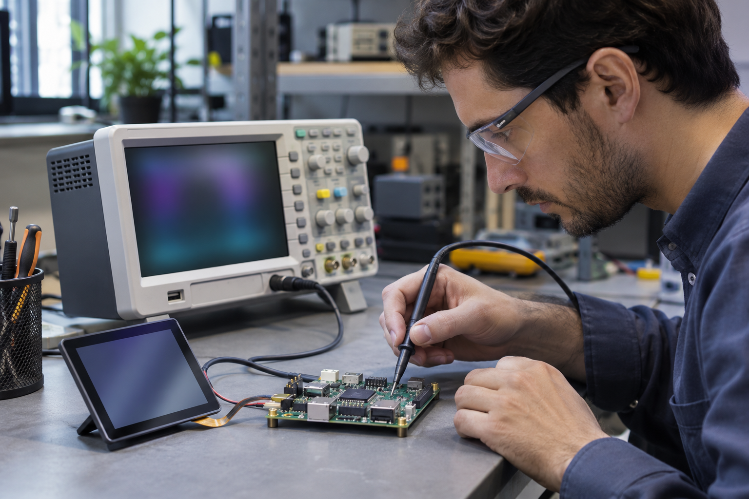
Use a suitable oscilloscope and probe at accessible points on the real assembly. Compare supply, SDA, SCL, and reset, where accessible, at startup and during a failed transaction. Look for slow rising edges, invalid high or low levels, noise, missing activity, or an unexpected reset. Measure rise time and low level against the applicable bus mode and device limits. Probe capacitance and grounding can change the measurement, so use the probe manufacturer’s guidance and account for loading.
If documentation and the controller permit it, a lower I²C clock rate can be a useful diagnostic comparison. Improvement may indicate a timing or signal-integrity problem, but it does not prove which component caused it or make an out-of-spec bus acceptable. Test representative cable routing and adjacent operating loads in the finished enclosure.
Make the next change measurable
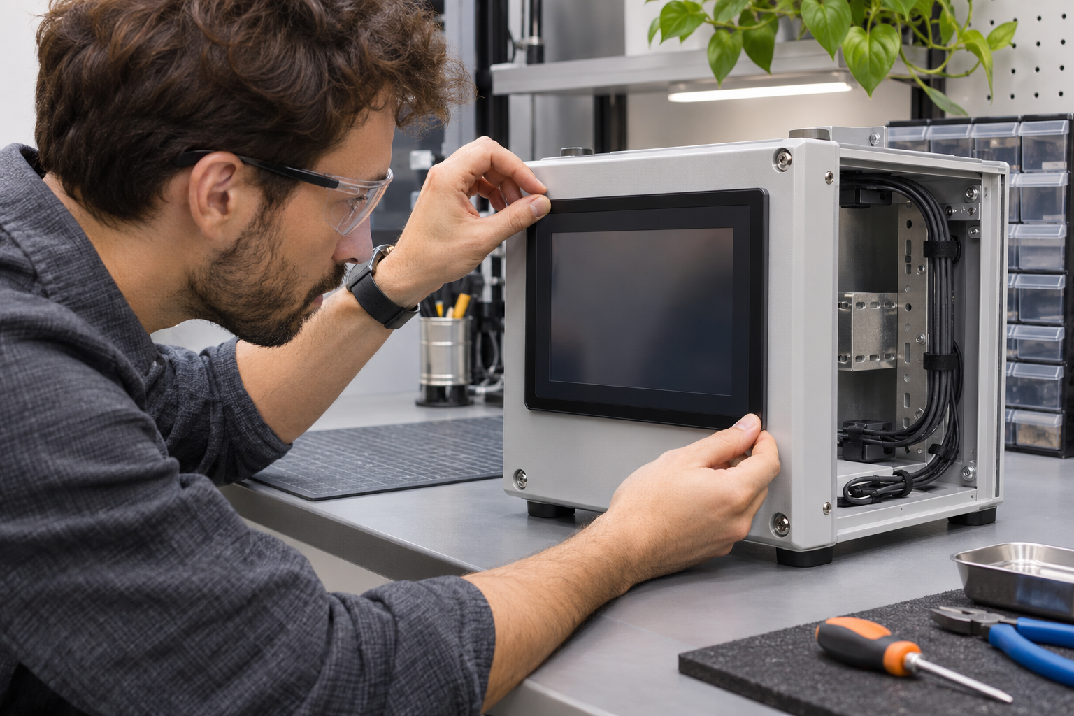
Change one factor at a time and repeat the same touch test. For example, compare the original and installed cables, confirm the effective pull-up network, or verify reset timing. Power down before changing connections and handle the module using appropriate electrostatic discharge precautions. After a change, check communication across startup, normal use, and expected operating conditions. If the bus is healthy but touches are still unreliable, investigate sensor configuration, grounding, cover stack, and environmental interference. A touch response on one power cycle is not enough to establish a reliable design.
For other display and touch symptoms, see the industrial display diagnosis guide. For an integration review, в RJY Display with the panel and touch-controller model, host interface, wiring, power sequence, and measured bus behavior. Any proposed match depends on the actual module and system.
Часто задаваемые вопросы
Does a working LCD image prove that I²C touch is connected correctly?
No. Display and touch often use separate signals, controllers, power requirements, and software paths.
Should I always use a smaller pull-up resistor?
No. A smaller value may improve the rise time but can exceed a device’s ability to pull the line low. Check both limits for the actual bus.