Facing a bottleneck in your Embedded Display Project?
Don’t let complex integration or supply chain issues slow your time-to-market. Book a free consultation with the RJY expert team for tailored design and manufacturing support.

A display in a handheld test instrument does more than present a large number. It may need to render continuously changing waveforms, dense menus, status indicators, thermal images, cursors, alarms, and touch controls while sharing a limited power and thermal budget with the measurement electronics.
That combination makes display selection a system-level engineering task. Resolution, interface, backlight, touch technology, graphics performance, mechanical integration, and electromagnetic behavior should be considered together. A panel that looks suitable on a datasheet can still create problems if the host cannot sustain the intended interface, if the backlight dominates battery consumption, or if display activity interferes with a sensitive acquisition path.
The right display architecture depends first on what the operator must see and do. A handheld multimeter may emphasize one primary reading, secondary values, range status, and warning indicators. A portable oscilloscope may need several traces, a graticule, cursors, decoded buses, trigger controls, and frequent screen updates. A thermal imager may place a color image, palette, spot measurements, and menus on the screen simultaneously.
These workloads produce different requirements even when the enclosure dimensions are similar. Before selecting a module, the development team should build representative screens using realistic fonts, traces, icons, and controls. This reveals whether the intended resolution supports usable information density without making touch targets or critical values too small.
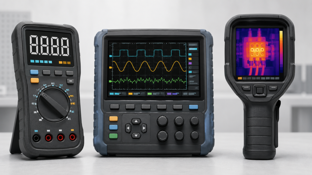
Aspect ratio also affects the workflow. A wide display can suit long waveform windows and side panels, while a squarer active area may fit compact instruments with controls below or beside the screen. The decision should follow the enclosure, grip orientation, control layout, and actual GUI—not a consumer-display convention.
Handheld instruments are rarely viewed only from a centered, perpendicular position. The operator may place the unit on a bench stand, hold it below eye level, rotate it during troubleshooting, or share the result with another person. Viewing-angle behavior should therefore be evaluated with the planned screen content and mechanical orientation.
Nominal brightness alone is not a complete readability specification. Cover glass, touch sensors, air gaps or optical bonding, surface reflections, backlight control, ambient illumination, and the use of dark or light GUI themes all affect the result. A higher backlight setting can improve visibility, but it can also increase battery drain and internal heat.
For indoor instruments, teams should validate readability under expected laboratory and factory lighting. For field equipment, they should also assess glare and outdoor visibility using a representative stack. Contrast stability, color shifts, minimum usable brightness, and reflections can be more informative than a single headline value.
RJY Display’s guide to TFT LCD viewing angles provides additional background, but the final acceptance test should use the selected module, touch or cover stack, enclosure, GUI, and viewing positions.
Display resolution affects more than image sharpness. It determines the number of pixels that the processor must generate, store, transfer, and update. Higher resolution can improve waveform detail and menu organization, but it can also increase framebuffer memory, bandwidth, rendering time, and power consumption.
The host architecture must be evaluated with the real GUI workload. A simple meter screen may run efficiently on an MCU using partial updates. A dense oscilloscope or thermal-image interface may require more memory bandwidth, graphics acceleration, or an MPU-class platform. The correct answer depends on color depth, update area, layer count, anti-aliasing, image processing, and the target interaction response—not simply the processor clock.
NXP’s display-system documentation illustrates an important architectural principle: a host display controller fetches graphics from memory and transfers them through a compatible display interface to the panel.1 The panel does not generate the application graphics or compensate for an undersized framebuffer architecture.
Prototype testing should include worst-case screens: several active traces, pop-up menus, rapid parameter changes, image palettes, and any animated status elements. Measure whether the GUI remains responsive while acquisition, storage, communication, and analysis tasks are running.
A TFT LCD module may use an MCU-style interface, RGB, LVDS, MIPI DSI, eDP, or another defined electrical and protocol path. Selection must begin with the native capability of the host processor or the controller architecture planned for the instrument.
Connector shape is not proof of compatibility. The team must confirm interface type, lane or bus configuration, voltage domains, pixel format, timing, initialization requirements, pin assignment, FPC geometry, and software support. Where a bridge or controller board is required, it becomes an active part of the system and adds power, startup, firmware, layout, and lifecycle considerations.
An HDMI source cannot drive a raw MIPI, RGB, LVDS, or eDP panel through a passive cable. Conversion requires an appropriate active controller or bridge designed and configured for the source and the exact panel. Likewise, an Android or embedded computing board is a host platform; it is not the LCD module itself, and touch input normally follows a path separate from video.
Early interface validation should use the intended host, cable or FPC length, power sequence, software build, and representative update pattern. A static test image is not sufficient to prove reliable operation under continuous waveform or image updates.
The LCD is outside the measurement chain, but it can still influence the surrounding electronics. Pixel clocks, serial display links, DC-DC converters, LED backlight drivers, touch scanning, and fast edge rates can create conducted or radiated energy. Sensitive analog front ends, high-impedance inputs, low-level sensors, or wide-band acquisition circuits may respond to that energy if the system is poorly partitioned.
This does not mean that a particular display interface is inherently unsuitable. It means the complete instrument needs deliberate power, grounding, routing, shielding, filtering, and mechanical planning. Display and touch flex cables should not be routed casually through sensitive input areas. Backlight current paths, converters, high-speed display signals, acquisition clocks, and analog references should be reviewed together.
Pre-compliance checks should compare measurement noise and accuracy-related behavior across relevant display states: screen off, minimum and maximum planned backlight, static screen, rapid waveform updates, active touch, and communication activity. Any observed coupling must be solved at the system level rather than hidden by reducing the test coverage.
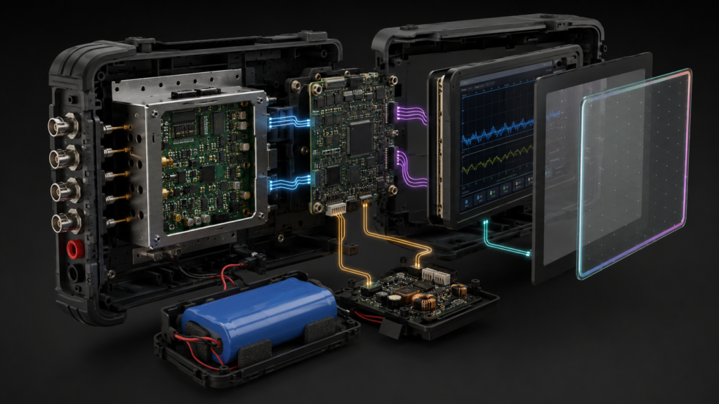
The LCD module does not establish an instrument’s measurement accuracy, calibration, input protection, or safety compliance. IEC 61010-1 covers general safety requirements for electrical test and measurement equipment, while IEC 61010-2-030 addresses equipment containing measuring circuits connected to external circuits.23 Compliance remains the responsibility of the finished equipment design and its applicable assessment process.
For a battery-powered instrument, the display subsystem can include the LCD rails, LED backlight, touch controller, host graphics workload, external memory, interface circuitry, and any bridge board. Focusing only on the panel logic current can therefore understate the system impact.
A useful power model separates operating states rather than assuming one fixed value. Examples include startup, active measurement at normal brightness, temporary high brightness, dimmed idle, display sleep, and full instrument standby. The planned transition behavior should be tested because power sequencing and wake recovery can affect both user experience and display reliability.
NXP has published examples in which the display controller and MIPI DSI subsystem are switched off and restored as part of a low-power mode.4 That example is platform-specific, but the broader lesson applies: display power management depends on coordination among panel commands, host controllers, power rails, memory, software state, and the backlight.
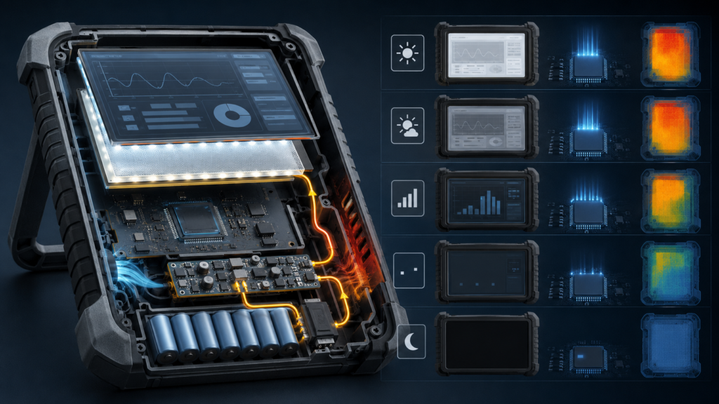
Brightness control should be tied to a defined use case. Confirm minimum stable brightness, dimming behavior, wake appearance, thermal behavior, and whether rapid modulation creates visible artifacts in the intended environment. RJY Display’s article on powering a TFT LCD display offers a starting point for module-level power planning.
Touch can make hierarchical menus, cursors, file browsing, annotation, and configuration easier. It does not automatically replace physical controls. Operators may need to adjust a range or acknowledge a hazardous condition without looking away from a probe position. Gloves, moisture, accidental contact, and bench use also change the interaction requirements.
A hybrid interface is often practical: touch for context-sensitive navigation and direct manipulation, with buttons, a rotary control, or other tactile inputs for frequent and safety-relevant actions. Touch-target dimensions should be validated on the final physical screen rather than only in design software.
Touch integration also introduces a separate electrical path. The team should confirm the sensor technology, controller interface, cover-glass stack, bonding approach, firmware behavior, grounding, noise immunity, and host-driver support. A video-compatible display connection does not prove touch compatibility.
Handheld equipment can experience grip pressure, drops, cable loads, vibration during transport, cleaning, and repeated connector use. The display should be integrated as part of the enclosure structure rather than treated as a decorative opening.
Review the active area, bezel, module outline, component keep-outs, FPC exit, bending radius, connector retention, mounting points, touch tail, backlight area, and tolerance stack. Cover glass can support impact protection and a product-specific user interface, but its thickness, printing, bonding, reflections, and touch performance must be evaluated together.
Optical bonding may be considered when reflection control, mechanical behavior, or environmental needs justify it, but it changes the assembly and service strategy. The choice should follow project requirements and validation, not a general assumption that every instrument needs the same stack.
A productive supplier review begins with system information. At minimum, provide the target active area and enclosure window, orientation, representative GUI, host processor, available display interfaces, resolution range, touch requirements, operating environment, backlight-control needs, cover or bonding concept, FPC constraints, project stage, and expected demand range.
The response should distinguish mandatory requirements from preferences. If an existing module satisfies the optical and electrical needs but requires a revised FPC, cover glass, backlight configuration, touch stack, or compatible controller solution, that may be a more controlled path than assuming a completely new LCD cell size can be created for the project.
RJY Display can evaluate projects around existing TFT LCD modules and applicable customization options, including cover glass, touch integration, backlight, FPC or interface changes, controller solutions, and mechanical coordination. Availability and feasibility remain dependent on the selected module and confirmed project requirements.
Evaluation should progress from module bring-up to an enclosure-level prototype and then to the intended production configuration. Testing only an open-frame sample on a development board misses optical, electrical, thermal, mechanical, and software interactions.
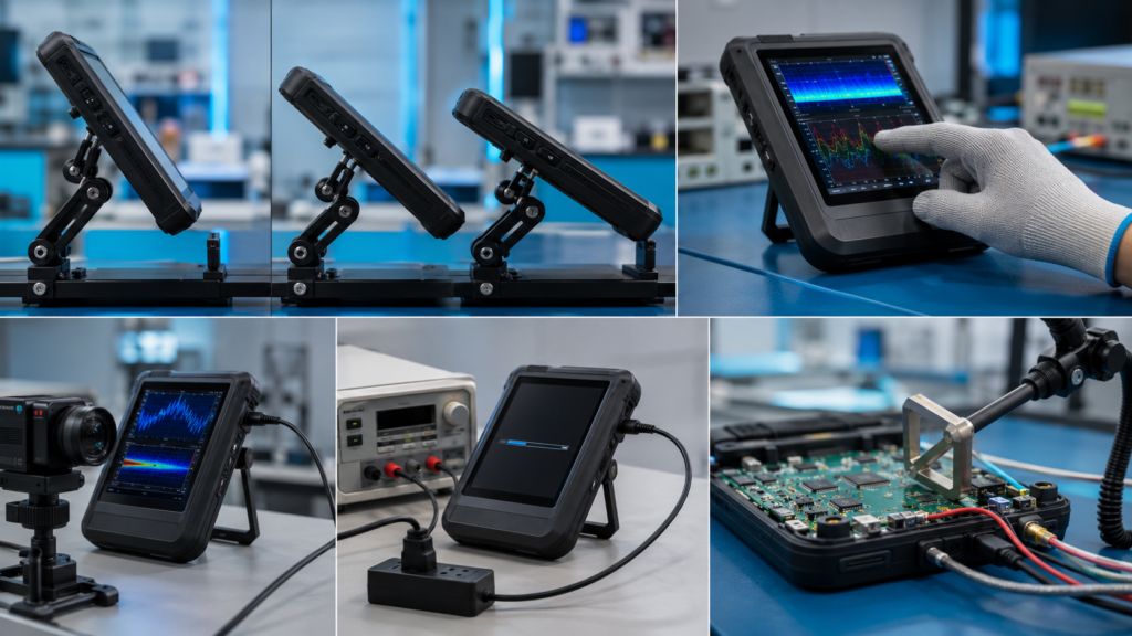
A practical validation plan should cover:
Acceptance criteria should be recorded before design freeze. This prevents subjective decisions such as “the display looks good” from replacing measurable system requirements.
The most suitable TFT LCD is not necessarily the panel with the highest resolution or brightest backlight. It is the module that supports the instrument’s information hierarchy, host architecture, power budget, physical use, measurement integrity, and lifecycle plan with manageable integration risk.
If you are selecting a display for a handheld oscilloscope, meter, data logger, thermal imager, analyzer, or related test instrument, prepare the host-interface details, enclosure drawing, target GUI, environmental conditions, and touch requirements before contacting a supplier.
Contact RJY Display for a project review to discuss an existing TFT LCD platform and relevant customization options. The review should confirm feasibility for the specific module and system rather than assume universal interface or mechanical compatibility.
There is no universally best interface. The correct choice depends on the host processor, resolution, pixel throughput, memory architecture, available pins, cable or FPC arrangement, power budget, software support, and the native interface of the selected panel. Compatibility must be verified at the electrical, timing, protocol, pinout, and software levels.
No. A passive cable cannot convert HDMI into a raw MIPI, RGB, LVDS, or eDP panel interface. The design requires an appropriate active controller or bridge that supports the source, the panel interface, the exact panel timing, power sequencing, and initialization requirements.
Not necessarily. Touch is useful for menus, cursors, file operations, and direct manipulation, but tactile controls may remain preferable for frequent adjustments, gloved operation, or actions that must be performed without looking at the screen. Many instruments benefit from a hybrid touch-and-physical-control interface.
The LCD does not perform the measurement or determine calibration, but the display subsystem can introduce switching noise through its interface, backlight driver, power rails, touch scanning, or cable routing. The complete instrument should be tested across relevant display states to identify and control coupling into sensitive measurement circuitry.
Provide the target active area and enclosure window, orientation, host processor, native interface options, representative GUI, resolution range, touch and cover-glass needs, FPC constraints, power and backlight requirements, operating environment, mechanical drawings, project stage, and expected demand range. Customization should be evaluated around a suitable existing LCD platform and confirmed project requirements.
Share your display size, resolution, interface, brightness, touch requirement, controller board requirement, and application environment.
Continue reading related display technology guides and application references.
Talk to RJY’s engineering team for display matching, controller board review, and customization discussion.