Capacitance sensing detects changes in electrical coupling. It can be used for buttons, proximity sensors, and liquid-level detection as well as touchscreens. In a touch display, the controller measures electrodes behind a cover, detects changes caused by a finger, and estimates its position.
Self and mutual capacitance measure different relationships. This affects how a sensor scans electrodes and interprets touches. The design must also distinguish a touch from noise.
What does capacitance sensing measure?
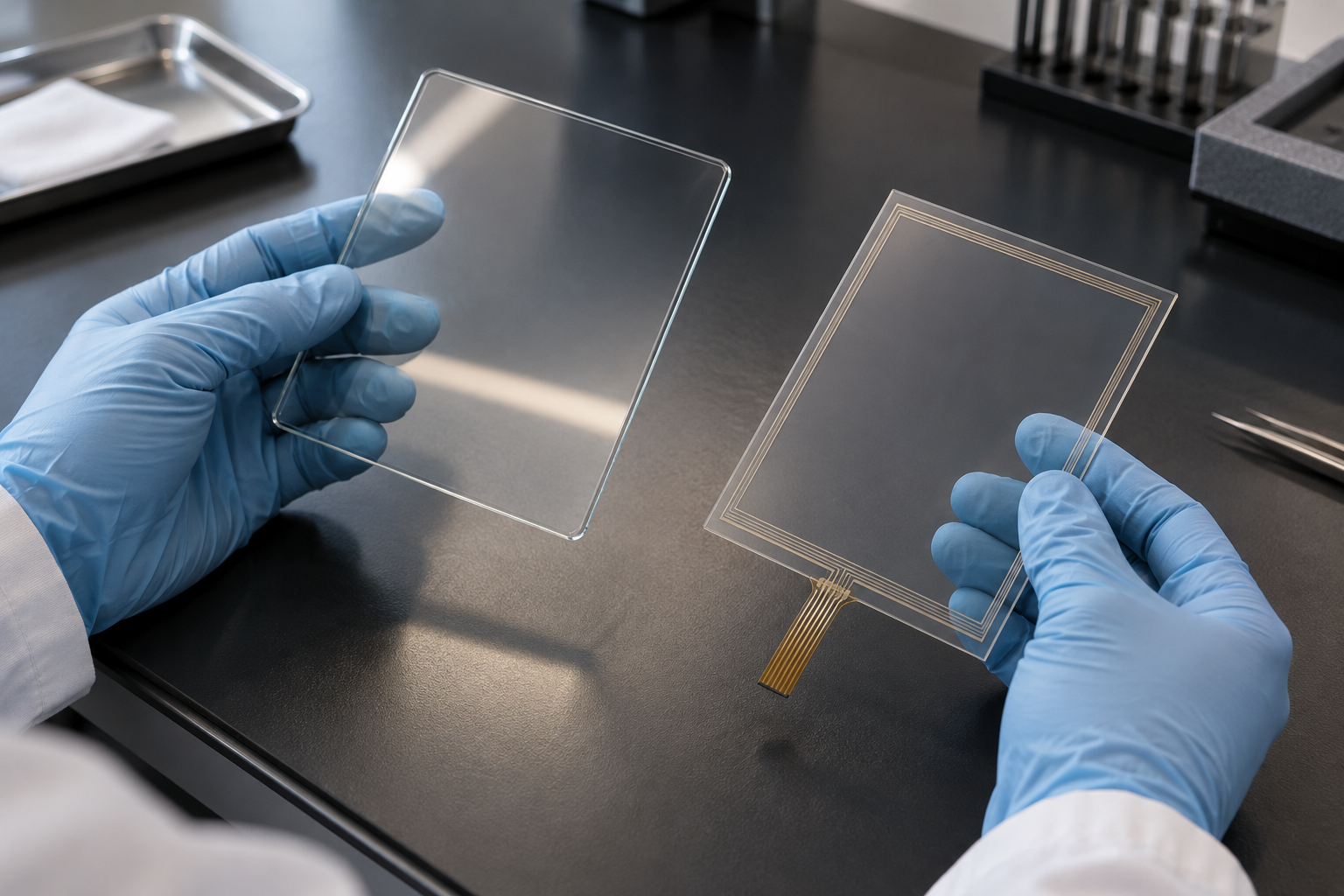
Capacitance describes how conductors store charge for a given voltage difference. A touch sensor uses electrodes separated from the finger by insulating materials, often including a cover lens. The controller measures a response related to capacitance. The finger need not press or make electrical contact with the electrode.
The untouched sensor has a baseline response. The controller compares later measurements with that baseline to find a meaningful change, often called the touch delta. It may track slow baseline changes over time and apply filtering and detection thresholds. The units and whether the reported count rises or falls depend on the electronics and software. A Texas Instruments example shows how one implementation relates raw readings, baseline, and threshold.[1]
Self capacitance and mutual capacitance
Self-capacitance sensing measures the apparent capacitance of an individual electrode relative to the sensing circuit’s reference. A finger couples to that electrode, while the person’s body also couples capacitively to its surroundings. A normal touch typically increases the measured capacitance. A person does not need a physical wire to earth for this interaction.[2]
Mutual-capacitance sensing measures the apparent coupling between a transmit electrode and a receive electrode. A finger near their interaction area changes the electric field and introduces another coupling path through the body and its surroundings. For an ordinary human touch, the measured mutual coupling typically decreases. The interaction has competing effects, so not every nearby conductive object produces the same response.[3]
| Self capacitance | Mutual capacitance | |
|---|---|---|
| Measurement | One electrode relative to the sensing circuit reference | Coupling between a transmit and a receive electrode |
| Typical effect of a finger | Apparent capacitance increases | Apparent mutual capacitance decreases |
| Position data | Individual electrode readings can be combined to estimate location | Individual transmit/receive intersections can provide a two-dimensional signal map |
These are measurement principles, not a guarantee about the number of supported touches. Projected capacitive touch, often called PCAP, describes a broader family of sensor implementations. For a general introduction to the structure, see PCAP touch screen technology.
How does a scan become a touch point?
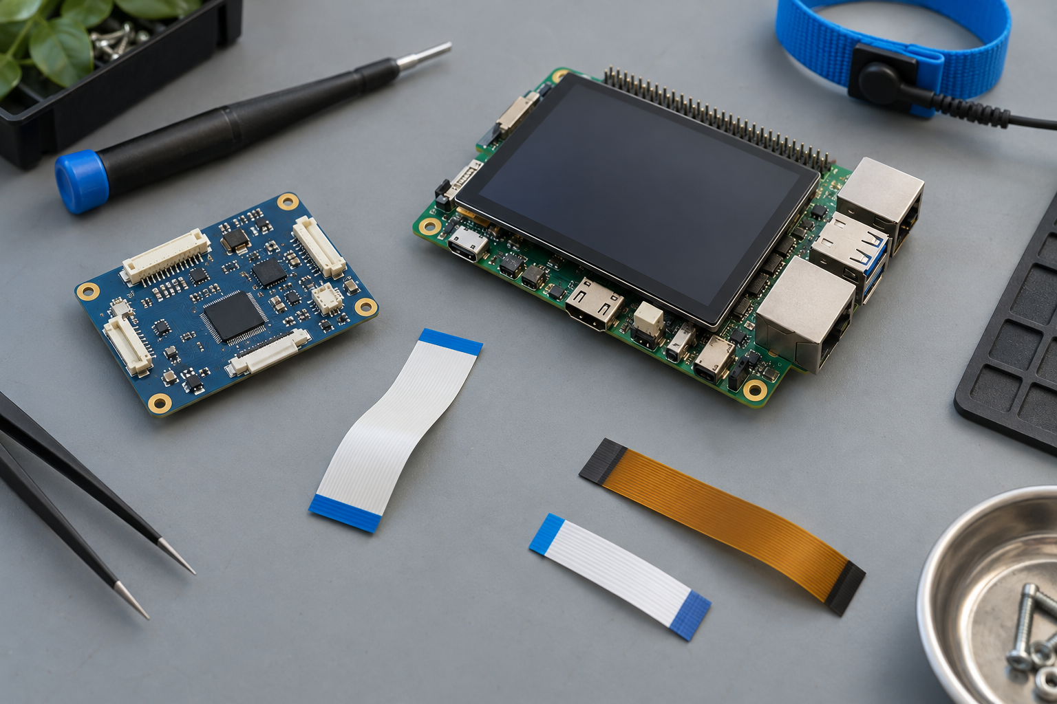
The controller scans sensor channels, compares their responses with untouched values, and identifies regions with a sufficient change. It estimates a position from those signals and reports coordinates to the host. Host software maps the coordinates to the displayed image and orientation.
In one simple self-capacitance matrix, the controller reads rows and columns separately. A single touch can be located by combining a row response with a column response. With two simultaneous touches in different rows and columns, the same readings can correspond to more than one pairing, creating ambiguous or ghost positions. This limitation applies to that matrix approach; it does not prove that every self-capacitance system is incapable of recognizing multiple touches.[4]
In a mutual-capacitance matrix, the controller can scan individual transmit/receive intersections. This provides position information at each measured node and can support multiple contacts without the same row-and-column pairing ambiguity. Actual touch count, separation, accuracy, and response depend on the sensor, controller, firmware, and operating conditions.[4] For the controller’s wider role, see what a touch IC does.
Why do the cover, layout, and surroundings matter?
Cover material and thickness, adhesive, air gaps, electrode geometry, cables, nearby conductors, and the display assembly can affect the measurement. A thicker cover generally weakens finger coupling; electrode and controller design may compensate within the system’s limits.[5]
Grounding and shielding also involve trade-offs. Nearby grounded structures can help control interference but can add parasitic capacitance and reduce sensitivity. Power supplies, display electronics, cables, and the user’s body can provide paths for electrical noise.[5]
Glove material and thickness change the interaction with the sensor. Water and moisture can change coupling and may produce unwanted detections. Confirm the required behavior with the actual cover, sensor, controller settings, and environment.
How should an OEM verify detection?
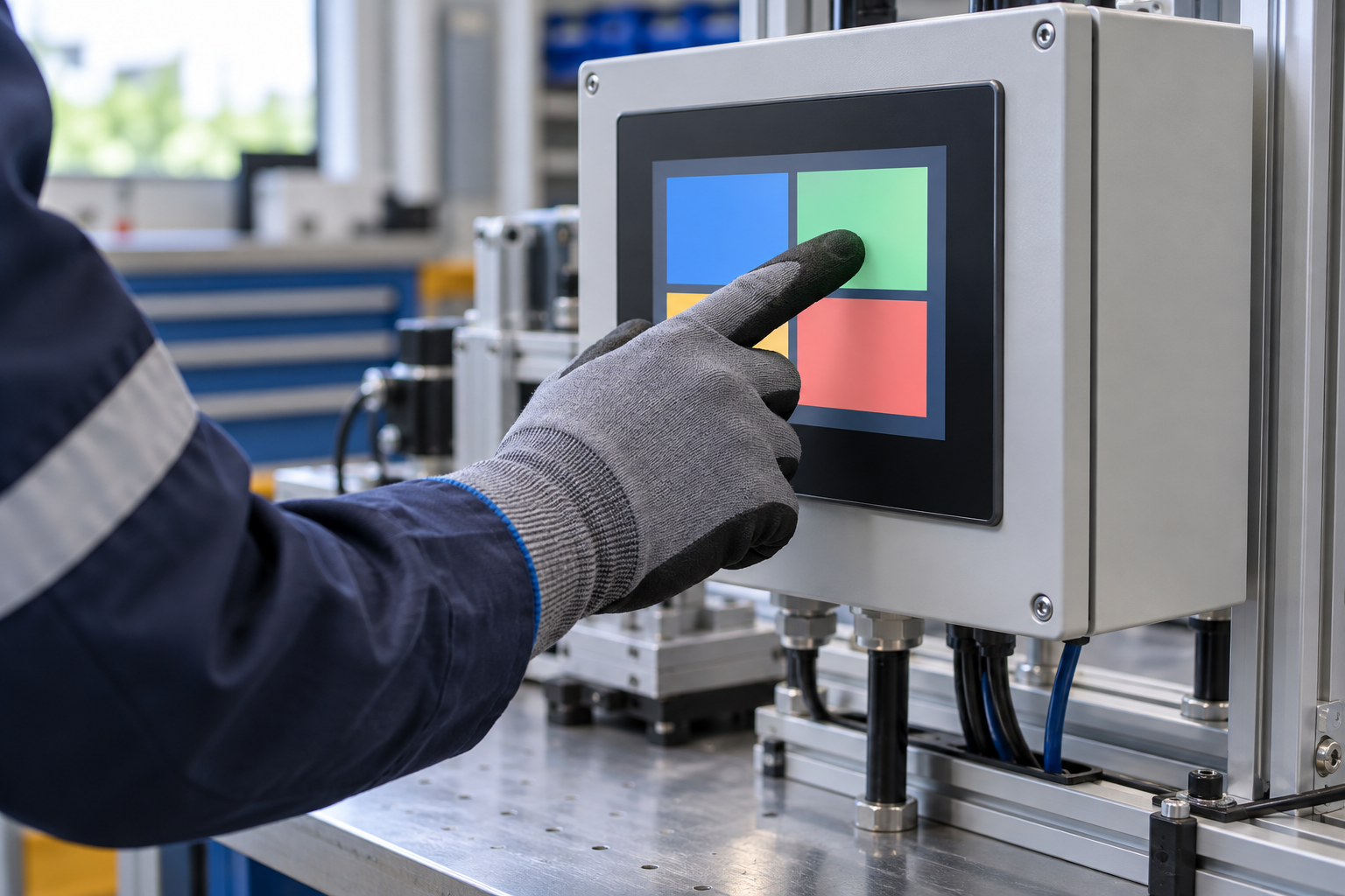
Test a representative finished assembly rather than relying only on a bare sensor. Record the display and touch revisions, cover and bonding stack, cables, grounding arrangement, host software, and controller settings. Agree the test conditions and acceptance limits before testing.
- Where the controller provides signal diagnostics, record untouched signal variation and the weakest valid touch signal at defined locations, including edges. Otherwise, record reported touch events and ask the supplier what diagnostic data is available.
- Measure missed touches, unintended touches, coordinate error, and response under the intended display and power conditions.
- Repeat relevant checks with specified gloves, moisture, temperature, or electrical disturbances when the application requires them.
- Reassess the test when a cover, cable, grounding path, display, or controller setting changes.
Filtering, threshold changes, and frequency selection can help a controller handle noise, but they also affect detection and response. Features and trade-offs are device-specific; Microchip describes one frequency-hopping implementation.[6] Requiring a larger touch delta can suppress weak valid touches as well as unwanted signals. Establish limits through the complete system test.
For display and touch selection considerations beyond sensing, see the TFT LCD module with touch screen guide. To discuss a specific design, contact RJY Display with the display, cover, host interface, use conditions, and touch requirements. Support depends on the particular project and components.
Frequently asked questions
Does a capacitive touchscreen measure finger pressure?
Capacitance sensing measures a change in electrical coupling. A basic capacitive measurement alone does not directly measure applied force; any pressure feature needs its own supported method.
Can self-capacitance sensing support multiple touches?
Some implementations can, but a simple self-capacitance row-and-column matrix can have ambiguous combinations when several points are touched. Check the specific sensor and controller design.
Does mutual capacitance guarantee multi-touch?
No. Scanning individual mutual-capacitance nodes can support multiple contacts, but the number and separation of contacts depend on the hardware, firmware, and test conditions.
Will a thicker cover or gloves always prevent touch?
No. They change the signal and may require a suitable sensor and tuning. Verify the specified cover and gloves on the completed assembly.
References
- Texas Instruments, Sensor Controller: Capacitive Touch.
- Texas Instruments, CapTIvate Technology Guide: Capacitive Sensing Basics.
- Microchip, QTouch Modular Library: Mutual Capacitance.
- Infineon, AN85951: PSoC 4 and PSoC 6 MCU CAPSENSE Design Guide, matrix buttons and touchpads.
- Microchip, AN2934: Capacitive Touch Sensor Design Guide.
- Microchip, Glossary of Touch Terms: Frequency Hop Parameters.