Facing a bottleneck in your Embedded Display Project?
Don’t let complex integration or supply chain issues slow your time-to-market. Book a free consultation with the RJY expert team for tailored design and manufacturing support.

Agricultural machinery displays operate at the intersection of outdoor optics, vehicle electronics, embedded graphics, touch input, machine control, and mechanical durability. A terminal in a tractor or combine may need to show guidance lines, field maps, implement settings, operating data, cameras, diagnostics, and alarms while the machine moves through changing light and terrain.
That workload cannot be reduced to a single brightness figure or screen size. The TFT LCD, touch layer, host computer, vehicle communication interface, wiring harness, enclosure, physical controls, and application software must be treated as coordinated but distinct parts of the HMI.
This guide explains how an OEM can define those requirements without assuming that one panel fits every vehicle or that an LCD module by itself provides ISOBUS functionality, machine control, environmental protection, or safety compliance.
Display requirements should begin with the operator’s tasks. A compact tractor terminal may emphasize machine status and implement adjustment. A combine display may combine harvesting data, machine settings, yield information, guidance, and camera views. A universal terminal may need to present interfaces supplied by different connected implements.
Build representative screens before choosing the panel. Include realistic maps, guidance paths, alarm messages, implement controls, status regions, camera windows, fonts, languages, and day/night themes. This reveals how much active area and resolution are actually required.
A higher resolution can improve map detail and information organization, but it also increases framebuffer memory, graphics bandwidth, rendering load, interface throughput, and potentially power consumption. The correct resolution is the one the selected host can update reliably under the worst combined workload—not necessarily the highest available specification.
Screen aspect ratio should follow the interface. A wide format may suit mapping and split-screen views, while another application may benefit from a more compact rectangular or square active area. The enclosure, mounting position, steering wheel, windshield pillars, operator sightlines, and nearby physical controls all constrain the choice.
Agricultural displays can encounter direct sunlight, bright cloud cover, reflections from cab glass, low-angle sunrise or sunset glare, shadows, dust, fingerprints, and nighttime use. Nominal panel luminance is only one part of readability under those conditions.
The visible result depends on the LCD’s contrast and viewing behavior, the backlight, touch sensor, cover lens, gaps or bonding layers, surface reflections, GUI colors, font weight, mounting angle, and ambient light direction. Increasing the backlight may improve the contrast between emitted screen light and ambient illumination, but it does not eliminate front-surface reflections and can add power and thermal load.
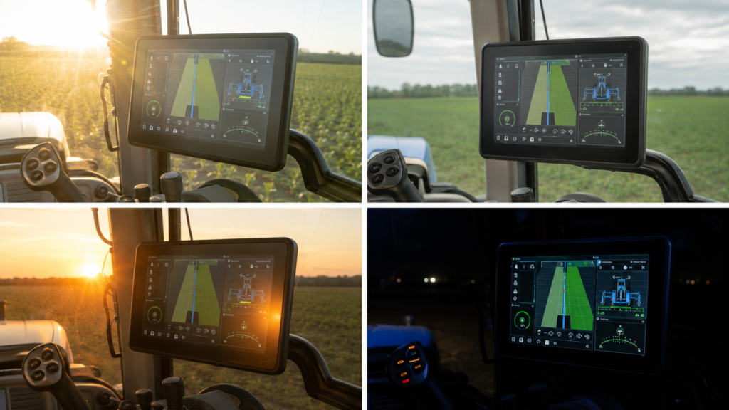
OEMs should define several real viewing conditions instead of one generic “outdoor” requirement:
Evaluate the final display stack in those conditions. RJY Display’s resources on sunlight-readable displays and TFT LCD viewing angles provide starting points, but a category label or panel datasheet does not replace vehicle-level optical validation.
A display selected only for maximum daytime output can still produce an unsatisfactory nighttime interface. The system must support a usable dimming range, appropriate GUI themes, controlled startup appearance, and predictable transitions between operating states.
Backlight control should be coordinated among the LCD module, driver circuitry, host software, ambient-light strategy, and vehicle power state. The team should check minimum stable brightness, visible modulation, image readability, color behavior, wake transitions, and whether the backlight changes affect nearby electronics.
The GUI should not rely solely on color to communicate important conditions. Day and night palettes should preserve hierarchy, contrast, alarm recognition, and map legibility. Test representative dirty screens and reflected cab interiors rather than reviewing the GUI only on a desktop monitor.
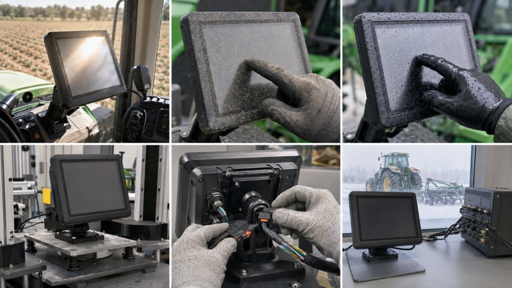
Touch can be useful for maps, menus, implement setup, data entry, and contextual controls. Agricultural machinery, however, may be operated with work gloves, dirty hands, moisture on the surface, vibration, and frequent attention directed outside the cab.
A hybrid interface is often worth evaluating. Touch can handle flexible navigation, while a joystick, rotary control, or physical keys can support high-frequency operations that benefit from tactile feedback. The appropriate division depends on the machine, risk analysis, operator workflow, and software design.
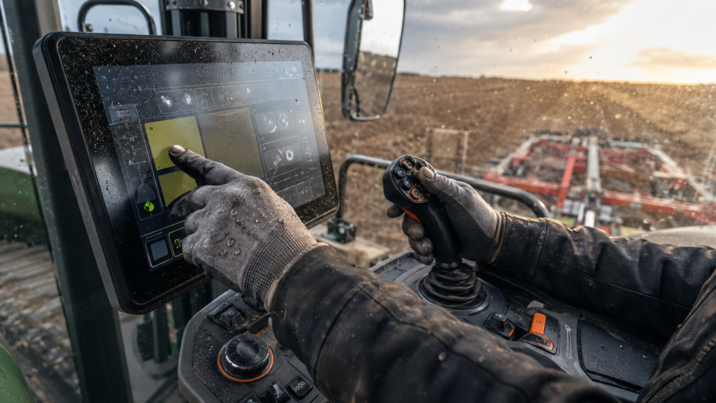
Touch performance cannot be inferred from the words “capacitive touchscreen.” The final behavior depends on the sensor, controller, firmware, cover material, stack thickness, grounding, noise environment, glove, water, contamination, target size, and mounting. Not every capacitive system supports every glove or wet-use condition.
Validate deliberate touches, dragging, edge targets, multi-touch if required, palm contact, droplets, dust, and vibration with the production-intent stack. Controls that are difficult to activate while stationary may become significantly harder to use when the machine is moving.
An agricultural HMI typically contains several separate functions:
A CAN or ISOBUS connection does not directly drive raw pixels into an LCD panel. Vehicle or implement data is received and interpreted by a compatible host system, which renders the interface and then drives the LCD through its native display path.
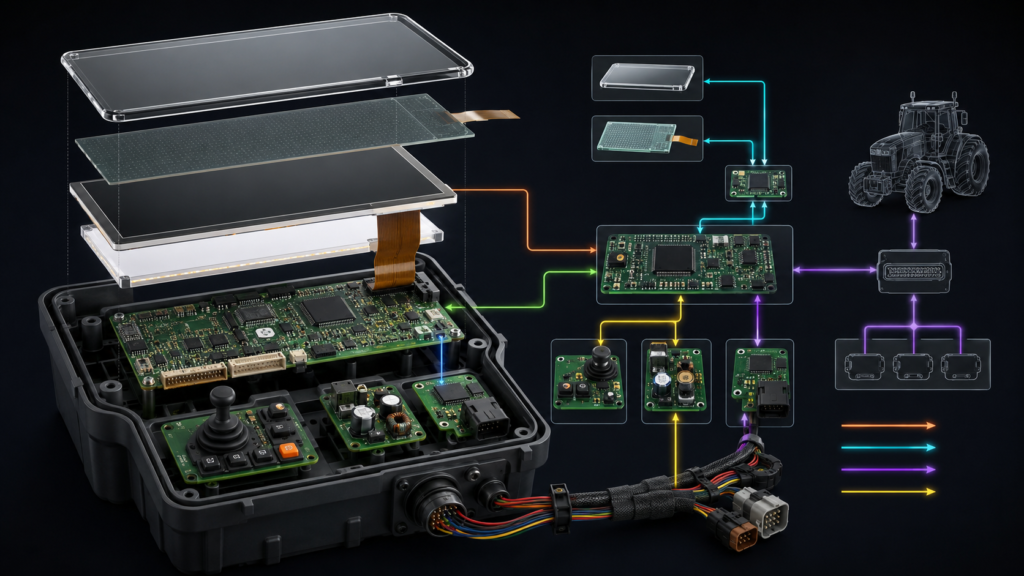
ISO 11783 specifies a serial data network for communication and control on agricultural and forestry tractors and implements. Its stated purpose includes standardizing data transfer among sensors, actuators, control elements, information storage and display units.1 The Agricultural Industry Electronics Foundation describes the Universal Terminal functionality as enabling an implement to be operated through a compatible terminal, subject to the functionalities supported by the participating components.2
Those concepts apply to a complete terminal architecture. Purchasing an LCD module or generic Android board does not, by itself, create an ISOBUS Universal Terminal or establish protocol conformity.
The LCD may use RGB, LVDS, MIPI DSI, eDP, or another defined panel interface. Selection should begin with the host processor, graphics bandwidth, supported interfaces, software platform, board layout, connector arrangement, power domains, and the exact panel timing requirements.
A matching connector is not sufficient evidence of compatibility. Engineers must confirm interface type, voltage, pin assignment, lane or bus configuration, pixel format, timing, initialization, power sequence, backlight control, and software support.
If a host exposes HDMI while the panel uses raw MIPI DSI, RGB, LVDS, or eDP, a passive cable cannot perform the conversion. The design requires a suitable active controller or bridge configured for both the source and the exact panel. That device becomes part of the startup, firmware, power, thermal, EMC, and lifecycle plan.
The external vehicle harness should also be distinguished from the short internal panel connection. Extending a raw LCD FPC interface through a long vehicle cable should never be assumed acceptable. The terminal-to-vehicle link needs its own deliberately engineered communication, power, grounding, shielding, connector, strain-relief, and fault-recovery architecture.
Agricultural machinery exposes the display assembly to sustained vibration, intermittent shock, cab resonance, connector motion, and harness loads. A panel that functions on an open-frame development bench has not demonstrated suitability in the machine.
Mechanical design should review the LCD outline, active area, bezel, component keep-outs, FPC exit, bend radius, connector retention, backlight frame, support points, cover stack, seals, fasteners, enclosure ribs, mounting arm, and external harness. Structural loads should not be concentrated on the LCD glass or transferred through the FPC.
Environmental tests must be derived from the finished product requirements. IEC 60068-2-64, for example, provides a method for random-vibration testing intended to assess whether a specimen can resist specified dynamic loads without unacceptable functional or structural degradation.3 Citing that test method does not establish a universal vibration profile for every tractor, implement, terminal, or LCD module.
The OEM should determine test axes, mounting fixture, spectrum, duration, operating state and acceptance criteria from the intended equipment and applicable requirements. Testing only a loose panel would miss the enclosure, mount, harness and connector interactions.
The display system may include LCD rails, an LED backlight, touch electronics, processor, memory, communication transceivers and supporting converters. Its power behavior must be evaluated as a terminal, not only as a panel.
Define startup order, backlight enable, communication initialization, GUI availability, sleep, wake, shutdown, power interruption and recovery. Check what the operator sees when implement communication is delayed or lost. A frozen map or stale status screen should not be mistaken for current machine information.
Power and backlight paths should be reviewed alongside grounding, vehicle transients, high-current actuators and radio equipment. RJY Display’s guide to powering a TFT LCD display explains module-level considerations, but vehicle supply conditioning and terminal-level protection remain part of the OEM design.
The LCD communicates information, but it does not automatically become a safety-related control-system component. A graphical warning, touch button or status icon can support operation only within the architecture and risk controls defined for the completed machine.
The ISO 25119 series addresses safety-related parts of control systems for tractors and machinery used in agriculture and forestry. ISO’s overview notes that the series considers matters such as system structure, fault detection, component reliability, operating stress and environmental conditions.4
The machine manufacturer must determine applicable safety functions, required performance, diagnostics, independent controls and validation. An LCD supplier should not claim that a panel, touch sensor, Android board or ordinary HMI establishes machine safety compliance.
Validation should move from electrical bring-up to an enclosure-level prototype and then to the production-intent host, LCD, touch stack, harness, mount, software and vehicle configuration.
A practical plan should include:
Acceptance criteria should be written before design freeze. “Readable outdoors” or “works with gloves” is too ambiguous unless the lighting, glove, contaminant, viewing angle, GUI, response and failure criteria are defined.
A useful supplier review should include the target active area, enclosure window, resolution range, orientation, representative GUI, host processor, available native display interfaces, touch and glove requirements, cover concept, mounting angle, lighting conditions, temperature expectations, vibration inputs, FPC and connector constraints, harness architecture, power sequence, controller-board requirement, project stage and expected demand range.
Separate mandatory requirements from preferences. A suitable existing LCD module combined with project-specific cover glass, touch, backlight, FPC, interface, controller or mechanical coordination may provide a more controlled path than assuming that a completely new LCD size can be developed for the project.
RJY Display can evaluate applicable customization around existing display platforms. Feasibility depends on the selected module and confirmed project requirements; it should not be interpreted as universal vehicle compatibility or an ability to develop any arbitrary LCD cell size from zero.
Contact RJY Display for an agricultural HMI display review and provide the host, interface, optical, touch, mechanical and application conditions before requesting samples.
No. Brightness is only one factor. Reflections, cover glass, touch layers, viewing angle, contrast, GUI design, cab geometry, ambient-light direction and dimming behavior also affect readability. The complete production-intent stack should be tested in representative daylight and nighttime conditions.
It may be possible with a suitable touch sensor, controller, firmware, cover stack and system design, but it should not be assumed from the term capacitive touch. The required gloves, droplets, contamination, grounding, vibration and target sizes must be tested with the final assembly.
No. ISOBUS carries agricultural machine and implement data within a compatible system. A host computer and software stack interpret that data, render the graphical interface and drive the TFT through its native display interface. The LCD module itself is not an ISOBUS Universal Terminal.
No. A passive cable cannot convert HDMI into a raw MIPI, RGB, LVDS or eDP panel interface. A compatible active controller or bridge must support the source, exact panel timing, initialization and power sequence.
Provide the active-area target, enclosure drawing, orientation, GUI examples, host processor, native interface options, touch and glove requirements, cover concept, viewing and lighting conditions, environment, vibration inputs, FPC and harness constraints, power sequence, project stage and expected demand range.
Share your display size, resolution, interface, brightness, touch requirement, controller board requirement, and application environment.
Continue reading related display technology guides and application references.
Talk to RJY’s engineering team for display matching, controller board review, and customization discussion.