Facing a bottleneck in your Embedded Display Project?
Don’t let complex integration or supply chain issues slow your time-to-market. Book a free consultation with the RJY expert team for tailored design and manufacturing support.

An industrial robot teach pendant places a dense programming and diagnostic interface in the operator’s hands. Its display may need to present robot position, coordinate systems, program steps, I/O states, alarms, operating modes, and graphical motion paths while the operator moves around a guarded cell.
This makes the TFT LCD part of a larger handheld control architecture rather than an isolated panel. Display size, resolution, viewing behavior, touch technology, physical controls, host processing, cable design, enclosure construction, and system validation must be evaluated together.
The LCD presents information, but it does not by itself implement an emergency stop, enabling function, motion control, safety-rated communication, or robot risk reduction. Those functions belong to the robot and pendant safety architecture and must be designed and validated under the standards and regulations applicable to the finished equipment.
A teach pendant is used for more than moving a robot from one point to another. Depending on the system, an operator may navigate programs, inspect coordinates, modify parameters, review alarms, monitor I/O, confirm tool states, or compare multiple data views. The display requirement should therefore begin with representative workflows and screens rather than a preferred diagonal size.
Build realistic interface mockups before selecting the panel. Include the longest expected alarm messages, target languages, program trees, coordinate values, soft keys, status areas, and any path or robot visualization. This exercise reveals whether the proposed resolution and aspect ratio provide enough information density without reducing critical text or touch targets to impractical sizes.
Commercial teach pendants illustrate the diversity of this workload. For example, one current industrial pendant uses a color touch panel and split-screen presentation so that two data sets can be viewed together.1 This is useful market evidence, but it is not a universal specification. Each OEM should derive the display requirement from its own robot controller, software, operator tasks, and enclosure.
Unlike a fixed control cabinet, a pendant changes position continuously. It may be held with two hands, supported with one hand, hung from a bracket, placed on a service stand, or viewed by two people during commissioning. The screen may be above, below, or to the side of the operator’s normal eye position.
Viewing-angle behavior should be tested in the intended orientation because LCD optical performance is not always symmetrical. A module that performs well in landscape orientation on a bench may show contrast or color changes after rotation or when viewed from the lower angles common during handheld use.
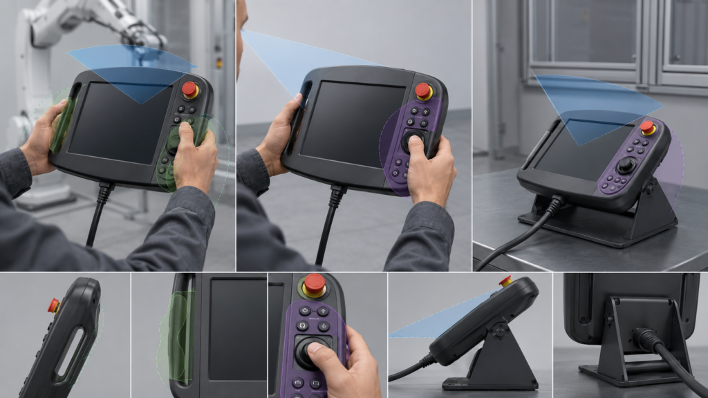
Brightness should also be evaluated as part of the complete optical stack. Factory luminaires, windows, protective cover glass, touch sensors, air gaps, surface treatments, and fingerprints can all affect readability. More backlight output is not automatically the complete answer because it can increase power and internal heat without eliminating surface reflections.
RJY Display’s guide to TFT LCD viewing angles explains the underlying viewing-direction issue. Final acceptance, however, should use the actual module, cover or touch stack, enclosure angle, GUI colors, fonts, and factory lighting.
A larger panel can display more information, but it also affects pendant width, grip reach, mass distribution, bezel space, impact protection, and access to physical controls. A high-resolution panel can improve program and path visualization, yet it increases framebuffer size, rendering load, memory bandwidth, and pixel-interface requirements.
Pixel density should be judged at the expected viewing distance. The goal is not to maximize a specification but to keep important values, mode indications, alarms, and controls legible while the operator is concentrating on the robot cell.
The active area must also coexist with mechanical elements. Space may be needed for hand grips, a cable exit, physical keys, an emergency-stop device, an enabling control, seals, fasteners, internal ribs, and impact-absorbing structures. Selecting the LCD before establishing these zones can create a pendant that is visually impressive but uncomfortable or mechanically difficult to integrate.
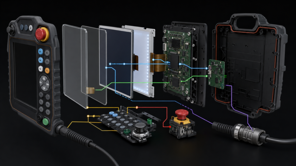
A complete teach pendant may contain several coordinated but distinct subsystems:
These elements should not be described as interchangeable. A touch event is not a video signal. An LCD is not an Android board. A display controller is not automatically a complete HMI, and an HMI computer is not automatically a robot safety controller.
ISO 10218-1:2025 addresses safety requirements for industrial robots, while ISO 10218-2:2025 addresses robot applications and integration.23 Display selection can support clear operation, but conformity of the robot and integrated application remains a system responsibility.
A graphical button may be appropriate for ordinary navigation or a non-safety command, but its appearance on a TFT does not make it a safety-rated control. Software state, a frozen GUI, a failed touch sensor, obscured content, or a communication fault can affect an on-screen function.
ISO 13850 specifies functional requirements and design principles for emergency-stop functions on machinery.4 The pendant and robot manufacturer must determine how applicable safety functions are implemented, monitored, identified, and validated. The LCD supplier cannot establish compliance by providing a display or touch panel.
This boundary also matters during content design. Mode information, warnings, faults, and motion state should be presented clearly, but visual information should not be claimed as the sole risk-reduction measure unless the complete safety architecture and applicable requirements support that conclusion.
Touch can support program navigation, parameter entry, graphical path inspection, menus, and context-sensitive controls. Physical inputs can remain valuable for frequent jogging operations, gloved use, tactile confirmation, or actions performed while the operator watches the robot rather than the screen.
The result is often a hybrid interface rather than a touch-only product. Define which tasks belong on the touchscreen and which require a physical control before laying out the enclosure. This decision influences the display size, cover-glass outline, grip width, button position, internal PCB arrangement, and software navigation.
Touch technology should be evaluated with the planned cover stack, glove types, contamination, grounding, cable arrangement, touch-controller firmware, and industrial noise environment. A projected-capacitive sensor that responds well on an open development bench may behave differently after installation behind thicker cover glass or near switching equipment.
Touch compatibility is separate from display compatibility. The host must support the touch-controller interface and driver, while the video path must support the LCD’s native interface, timing, pixel format, and initialization.
A pendant display may use RGB, LVDS, MIPI DSI, eDP, or another panel interface, depending on the module and embedded host. The correct choice depends on pixel throughput, processor support, PCB layout, FPC length, connector configuration, power domains, software support, electromagnetic behavior, and lifecycle needs.
A connector that fits mechanically does not prove compatibility. The development team must verify interface type, voltage levels, lane or bus configuration, timing, pin assignment, color format, initialization sequence, backlight control, and power sequencing.
If the host provides HDMI but the selected panel uses raw MIPI DSI, RGB, LVDS, or eDP, a passive cable is not sufficient. An active bridge or controller matched to both the source and the exact panel is required. That active device adds power, firmware, startup, thermal, PCB, and lifecycle considerations.
NXP’s display-system documentation provides one concrete example of a host display controller fetching graphics from memory and transferring them through a MIPI DSI host to a compatible panel.5 Although the implementation is platform-specific, it demonstrates why the complete pixel path must be designed rather than inferred from connector appearance.
The internal connection between a host board and TFT module is usually different from the external connection between a pendant and robot controller cabinet. The external cable may be long, repeatedly flexed, pulled, stepped on, exposed to factory noise, or routed near motors and power equipment.
The system architect must decide which processing occurs inside the pendant and which data crosses the external cable. The cable link needs an intentionally designed electrical architecture, connector, grounding approach, shielding, strain relief, bend management, communication protocol, and fault behavior.
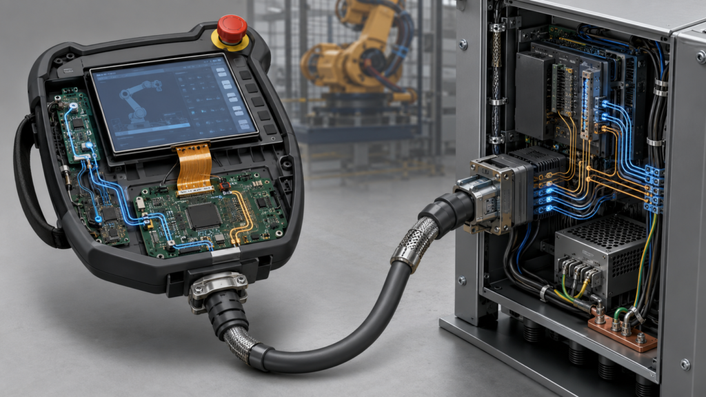
It is unsafe to assume that a short raw LCD FPC interface can simply be extended through a long pendant cable. Signal integrity, electromagnetic compatibility, connector cycles, cable motion, startup, and recovery must be verified for the selected architecture.
Inside the pendant, keep the panel FPC within its permitted bend and routing conditions. Confirm connector retention and prevent enclosure pressure, grip loads, or cable movement from being transferred to the display tail.
The LCD module is only one layer in the front assembly. The stack may include a protective cover, printed border, touch sensor, adhesive or optical bonding layer, gasket, frame, and enclosure supports. Each layer influences reflections, touch performance, display appearance, tolerance, repair strategy, and impact behavior.
The enclosure should support and protect the display without concentrating stress on the LCD glass. Review the active area, module outline, bezel, component keep-outs, backlight frame, FPC exit, connector access, screw bosses, sealing features, grip structure, and drop-energy paths.
Cover glass, surface treatment, bonding and touch customization should be considered against actual environmental and service requirements. A thicker or more complex stack is not automatically better; it may change reflections, touch sensitivity, assembly yield, thickness and repairability.
RJY Display can evaluate applicable customization around a suitable existing display platform, including cover glass, touch integration, backlight, FPC or interface changes, controller solutions and mechanical coordination. Feasibility depends on the selected module and confirmed project requirements; it should not be interpreted as an ability to create any arbitrary new LCD size from zero.
The pendant display subsystem may include panel power rails, LED backlight, touch controller, processor, external memory, communication hardware and supporting converters. Power analysis should therefore cover the complete architecture instead of quoting only the LCD logic current.
Define the expected sequence for robot-controller startup, pendant connection, display initialization, backlight activation, GUI availability, communication loss and recovery. The operator should not be left with a misleading frozen image if the host or controller link has failed.
Test repeated power cycles, interrupted startup, cable reconnection if permitted by the system, brownout conditions, display sleep and software recovery. Status presentation must be coordinated with the robot architecture; the display should not imply that the machine is in a safe state merely because the screen is dark or unresponsive.
RJY Display’s guide to powering a TFT LCD display provides module-level background, but the finished pendant requires a system-specific power and recovery design.
A panel displaying a static test image on an evaluation board is not a validated teach-pendant display system. Testing should progress from electrical bring-up to an enclosure-level prototype and then to the production-intent pendant, cable and controller configuration.
The validation plan should include:
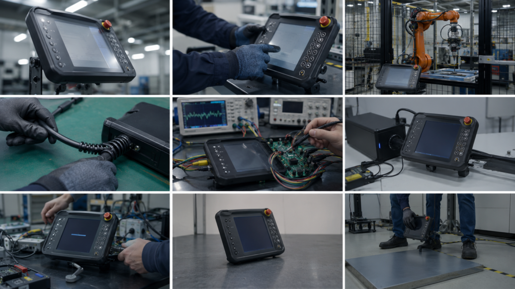
Applicable safety, environmental and regulatory testing must be determined by the robot manufacturer or integrator. Passing a module-level display test does not establish compliance for the completed robot or robot application.
Before requesting samples, provide the intended active area, resolution range, orientation, representative GUI, host processor, native display interfaces, touch requirements, cover-glass concept, physical-control layout, viewing positions, factory environment, cable architecture, enclosure drawing, FPC constraints, power sequence, project stage and expected demand range.
Separate mandatory requirements from preferences. A mature existing LCD module combined with an appropriate touch stack, cover, FPC, backlight or controller solution may offer a more controlled development path than beginning with an assumed custom panel geometry.
For a robot teach pendant project, contact RJY Display for a compatibility and customization review. Include enough system information to evaluate the display, touch, host interface and mechanical stack as coordinated components. Final suitability and safety remain subject to the finished equipment design and its validation process.
There is no universal size. The display must accommodate the planned program, coordinate, alarm and status screens while leaving enough enclosure space for grips, physical controls, cable routing, sealing and impact protection. Evaluate representative GUI screens at the intended viewing distance before selecting the diagonal size and aspect ratio.
Touch can support navigation, data entry and graphical programming, but it should not automatically replace tactile controls needed for frequent, gloved or eyes-on-robot operation. A graphical control also does not become a safety-rated emergency-stop or enabling function merely because it appears on the display.
No. HDMI cannot drive a raw MIPI, RGB, LVDS or eDP panel through a passive cable. An appropriate active controller or bridge must support the HDMI source, the panel interface, exact timing, power sequence and initialization requirements.
That should never be assumed. Raw panel interfaces are normally designed for a defined connection between the host and LCD. A long, moving external pendant cable requires an intentionally engineered system link with suitable signal integrity, shielding, grounding, connectors, strain relief, communication behavior and validation.
Provide the target active area, orientation, GUI examples, host processor, native interface options, touch and cover requirements, physical-control layout, enclosure drawing, FPC constraints, viewing positions, operating environment, cable architecture, power sequence, project stage and expected demand range. This allows the supplier to evaluate a suitable existing LCD platform and applicable customization.
Share your display size, resolution, interface, brightness, touch requirement, controller board requirement, and application environment.
Continue reading related display technology guides and application references.
Talk to RJY’s engineering team for display matching, controller board review, and customization discussion.