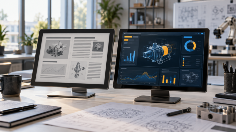
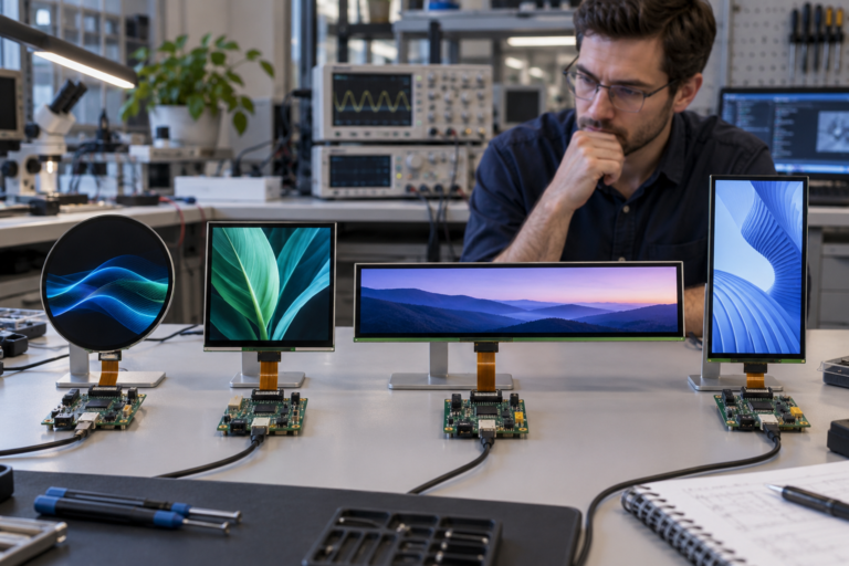
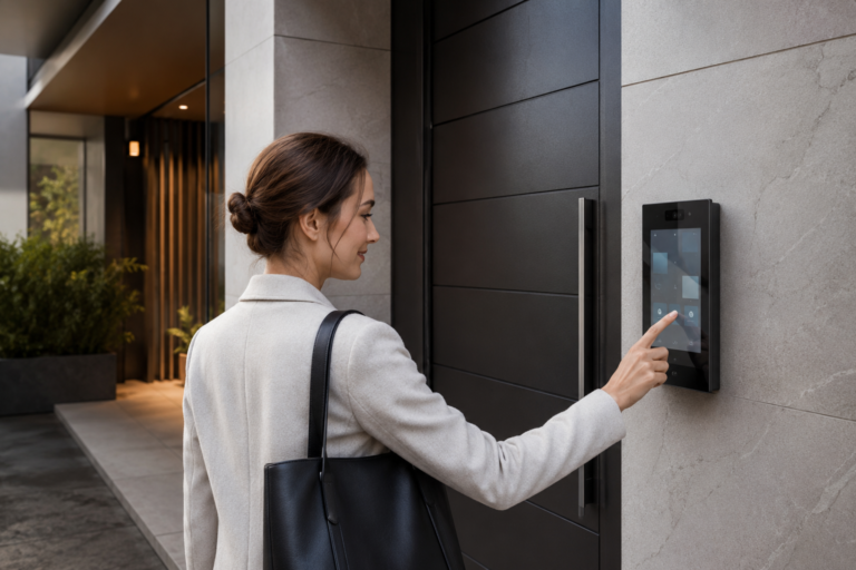
Facing a bottleneck in your Embedded Display Project?
Don’t let complex integration or supply chain issues slow your time-to-market. Book a free consultation with the RJY expert team for tailored design and manufacturing support.

A wireless CarPlay screen looks like one product from the driver’s seat. Behind the cover glass, however, it is a system made from several parts: an LCD, touch sensor, touch controller, head-unit processor, wireless hardware, audio circuits, vehicle connections, power conversion, software, and a mechanical structure.
This distinction matters for companies developing a car screen, touch stereo for a car, truck radio, or custom automotive head unit. The LCD does not create CarPlay capability. It shows the image produced by the head unit. The touch system reports input. The computing and wireless platform manages the phone connection, software, audio, and vehicle functions.
This guide focuses on that hardware boundary. It explains how OEMs, automotive accessory brands, equipment manufacturers, and engineering teams can choose a display, touch stack, controller-board path, and mechanical design for a CarPlay-oriented product. It does not present a consumer shopping list or claim that one screen fits every car, head unit, or iPhone.
In consumer language, a wireless CarPlay screen is a display that lets a driver use supported iPhone functions through an in-vehicle interface without connecting the phone with a cable for each drive. Apple describes CarPlay as a way to use functions such as directions, calls, messages, and music through a vehicle’s built-in display and controls.1
The phrase can describe several different product structures:
These products may all appear in searches for a car screen or touch screen stereo, but their engineering requirements differ. A portable screen may use a complete housed monitor architecture. A replacement radio may use a standard head-unit chassis and an external or integrated display. An OEM product may connect a raw LCD module and touch panel directly to a dedicated computing platform.
A TFT LCD receives pixel data and produces an image. A touch sensor detects input. Neither component establishes the CarPlay session, runs the user interface, manages Bluetooth or Wi-Fi, routes audio, or communicates with vehicle controls.
The host platform must provide the required CarPlay-related hardware and software capability. Apple’s setup instructions for a wireless-only vehicle tell the user to place the stereo in wireless or Bluetooth mode and ensure that Wi-Fi is enabled on the iPhone.2 This shows why the word “wireless” belongs to the head-unit connectivity architecture, not to the LCD panel.
For an OEM display project, divide responsibility into clear subsystems:
| Subsystem | Primary Function | Key Integration Questions |
|---|---|---|
| TFT LCD | Displays the image | Size, resolution, timing, interface, pin definition, backlight, viewing direction, and mechanical outline |
| Touch sensor and controller | Detects input and reports coordinates | Touch technology, controller, firmware, interface, driver, cover glass, grounding, and required gestures |
| Head-unit processor | Runs the system and generates the display content | Operating system, graphics output, startup behavior, software ownership, and supported peripherals |
| Wireless hardware | Supports the required phone connection | Radio hardware, antennas, coexistence, firmware, qualification, and software integration |
| Audio system | Handles media, calls, microphone input, and output routing | Amplifier, speakers, microphone, echo behavior, vehicle audio connection, and volume control |
| Vehicle interface | Connects power, controls, cameras, and vehicle signals | Vehicle architecture, harness, power events, steering controls, reverse signal, cameras, and installation responsibility |
A display supplier can help review the LCD, touch assembly, cover glass, display controller, FPC, backlight, and mechanical fit. It cannot confirm that an unverified head-unit platform is authorized for or compatible with the CarPlay ecosystem. That decision belongs to the complete system owner and the relevant platform program.
The LCD defines the visible area, resolution, aspect ratio, native timing, viewing characteristics, interface, and much of the mechanical envelope. Its LED backlight defines a large part of the display power and thermal load. The head unit or controller board must supply the correct panel signals, power sequence, and backlight control.
Many modern head-unit concepts use projected capacitive touch because it can support a glass front and gesture-based interaction. The exact behavior depends on the sensor, controller, firmware, cover lens, grounding, electrical environment, operating system, and application. A claim such as “multi-touch” is incomplete until the project defines how many simultaneous contacts it needs and which gestures must work.
The host processor renders the interface and sends image data to the display. It may drive a panel-level interface directly or send a standard video signal to a separate controller board. This choice affects PCB design, firmware responsibility, cable count, startup time, cost, and enclosure depth.
The wireless subsystem includes more than a radio chip. It may require antennas, RF layout, software stacks, pairing logic, reconnection behavior, coexistence management, and product-level validation. Its physical location also matters. A metal housing, display frame, cable, or other electronic subsystem can affect the RF environment.

A touch screen stereo must send media and call audio through a defined route. It also needs microphone input and user controls. An aftermarket unit may connect to an auxiliary input, FM path, amplifier, or vehicle harness. An OEM system may integrate more deeply with the vehicle network and audio architecture. These functions are outside the LCD, even though the display presents their controls.
| Architecture | Main Advantage | Main Integration Work | Display Implication |
|---|---|---|---|
| Portable dashboard screen | Can add an interface without replacing the original radio | Mounting, power cable, audio route, camera input, and driver visibility | Usually needs a complete housed display with its own electronics |
| Aftermarket head unit | Replaces or upgrades the original stereo system | Dashboard fit, harness, controls, audio, antennas, cameras, and vehicle-specific installation | May use an integrated or detachable touch display assembly |
| OEM embedded infotainment system | Can match the dashboard and vehicle electronics from the start | Full hardware, software, mechanical, vehicle, qualification, and lifecycle program | Often uses a panel-level interface and custom touch/cover assembly |
| Truck or fleet terminal | Can combine navigation, media, cameras, and work functions | Cab mounting, power, vibration, driver reach, cameras, fleet system, and service access | May favor a larger open-frame or embedded display with large UI targets |
A portable screen is not automatically easier to engineer. It moves work from the dashboard cavity to the mounting system, external wiring, enclosure, and audio connection. An embedded display reduces external clutter but requires closer coordination with the host electronics and dashboard structure.
The correct diagonal size is the result of the dashboard space, viewing distance, driver reach, UI layout, and mounting structure. It is not simply the largest panel that fits across the console.
Define the available width, height, depth, corner radii, mounting points, and keep-out zones. Separate the LCD active area from the module outline and cover-glass outline. A nominal screen size does not describe the bezel, FPC, connector, controller board, or brackets.
Resolution affects text, icons, maps, camera images, and the graphics workload on the host. A higher pixel count can improve detail, but it also changes memory bandwidth, processor load, interface requirements, and scaling. Select resolution with the actual UI and host platform rather than treating it as an isolated quality score.
A conventional landscape panel can suit common dashboard layouts. A wide bar display may fit a narrow horizontal area. A portrait or floating display can create more vertical space for navigation and controls, but it changes mounting loads, viewing angles, cable routing, and UI organization.
Print or display the proposed UI at full size and place it at the intended angle. Check reach from the driving position, sightline, reflections, obstruction of vents or controls, and visibility for the passenger. The mock-up should include the cover-glass border and the real enclosure, not only the LCD active area.
A big screen car radio can provide more space for maps, cameras, media, and vehicle controls, but larger size introduces new constraints.
Large size should support the intended tasks rather than increase visual impact alone. NHTSA’s visual-manual driver-distraction guidance addresses in-vehicle communication, entertainment, information, and navigation tasks operated through driver visual and manual interaction.3 Product teams should treat UI workload, touch-target placement, and driver access as system requirements, not only software styling.
List the gestures the UI uses: tap, drag, swipe, pinch, long press, or simultaneous contacts. Define the smallest touch target and the expected operating position. A controller that reports several touch points does not prove that the final UI will work reliably behind the chosen cover glass.
The cover lens determines the visible front shape and protects the sensor. Its thickness, material, printed border, adhesive, air gaps, and distance from the sensor can change capacitive sensitivity. The product team should approve the lens, sensor, controller, firmware, grounding, and enclosure as one configuration.
Do not specify “glove touch” without naming the glove material and thickness. Do not specify “wet touch” without stating the liquid condition and required response. The system may need to accept deliberate input, reject false touches, or stop responding until the surface is dry. Each behavior needs a separate test.

The touch sensor operates near the LCD, backlight driver, processor, wireless radios, DC-DC converters, audio circuits, vehicle wiring, and external cables. Grounding, shielding, cable position, charger operation, and display activity can change the noise environment. Test the final electronics and enclosure rather than approving touch performance on an isolated bench sensor.
Automotive head-unit displays can use MIPI DSI, LVDS, eDP, RGB, or another embedded display interface. Prototype or aftermarket platforms may start from HDMI or another standard video output and use a controller board to drive the selected LCD.
The connector does not determine compatibility. Two panels can use similar FPC connectors while requiring different pin definitions, voltages, timing, initialization commands, backlight circuits, or interface modes.
A direct connection can reduce board count and package depth when the host processor supports the LCD’s native interface. It also places more responsibility on the product team. The host must supply the correct timing, data format, power sequence, initialization, and backlight control. Firmware and hardware revisions must stay aligned with the approved panel.
A controller board can accept a source such as HDMI and generate the signals required by a particular panel. This conversion is active and panel-specific. An HDMI-to-MIPI solution is not a passive adapter and should not be described as universal. The board firmware, output timing, cable, backlight driver, panel revision, and startup behavior must match the actual LCD.
The display interface carries the image. The touch controller commonly uses a separate USB, I2C, SPI, or other supported path. HDMI alone does not normally return touch coordinates. Confirm touch-controller drivers, voltage, reset, interrupt, wake, coordinate orientation, and operating-system support.
For related integration details, see the HDMI-to-MIPI controller-board compatibility guide and the broader LCD module interface guide.
The phrase “car stereo with Bluetooth and touch screen” combines several user-visible features, but the engineering team must separate them.
A fault in one subsystem can look like a screen fault. For example, the LCD may continue displaying the last image while the host software is unresponsive. Touch may fail while wireless audio continues. A phone may remain paired while the Wi-Fi link or application session does not recover. Build diagnostic states that help engineering and service teams identify which path failed.
Visibility depends on display luminance, ambient light, reflections, contrast, cover glass, bonding, viewing angle, and UI design. A brightness value by itself cannot prove sunlight readability. Define the installation angle, expected light direction, cover stack, UI colors, and acceptance method.
A display that looks clear during the day may be uncomfortable or distracting at night. The system needs a suitable dimming range and control strategy. Confirm whether the host changes backlight brightness through PWM, current control, a controller-board command, or another method. Software dark mode does not necessarily reduce backlight output.
The driver and passenger view the car screen from different positions. Check contrast, color shift, black-state behavior, and reflection from both seats. If the display also shows a camera image or important vehicle information, define which viewing positions must meet the project’s acceptance criteria.
Optical bonding can reduce internal air interfaces, but it does not automatically prove sunlight readability, impact resistance, environmental sealing, or automotive qualification. Anti-glare, anti-reflection, and anti-fingerprint treatments also require project-specific review for appearance, touch feel, cleaning, durability, and manufacturing feasibility.
A vehicle supply is not the same as a stable LCD power rail. The complete head unit needs appropriate input protection and power conversion for its target vehicle environment. The display module and touch controller then require their own specified rails, sequencing, reset behavior, and backlight supply.
Define what happens during:
The LCD, touch controller, processor, wireless radios, amplifier, and backlight all contribute heat. Measure the final assembly in the intended enclosure. A controller board that works in open air may run differently behind a large screen with limited ventilation. Mechanical supports and adhesive layers can also change heat paths.
A touch screen radio for a truck may be viewed from farther away and may share the cab with fleet, camera, navigation, or work functions. The UI may need larger targets and less dense information. The display position must account for the driver’s seated posture, steering wheel, sightline, windshield reflections, and cab movement.
Truck and commercial-vehicle projects should define:

The word “truck” does not by itself define a test standard or prove automotive qualification. Convert the application into measurable electrical, optical, mechanical, environmental, and lifecycle requirements.
An aftermarket headunit for a car, a fleet accessory, and an OEM vehicle program can use similar display technology while following very different development paths.
The supplier may target a defined set of installation formats or provide vehicle-specific accessories. The product still needs accurate compatibility information, safe mounting, power design, thermal review, and a clear installation process. It should not be described as compatible with every vehicle unless that claim has been validated.
The buyer may prioritize controlled installation, serviceability, camera input, telematics, repeated procurement, and a stable mechanical configuration. The display supplier must understand the equipment owner’s enclosure, host platform, cable routing, and volume plan.
The program can require formal component qualification, traceability, change control, documentation, long lifecycle planning, and system-level validation. A general TFT LCD specification does not prove that the module is automotive-qualified. RJY should discuss automotive-related use only against the exact module, program requirements, and available evidence.
Validate the complete product, not only the LCD sample.
Test native resolution, orientation, color behavior, viewing positions, brightness control, day and night settings, startup, sleep, wake, and signal recovery. Use maps, camera views, text, and the actual UI rather than one static demonstration image.
Test the center, edges, corners, printed-border areas, taps, drags, and required gestures. Verify coordinate mapping after rotation, startup, sleep, wake, and host recovery. Repeat the test with the final cover lens, enclosure, grounding, and cable layout.
Test first pairing, automatic reconnection, multiple known phones if the product supports them, interrupted sessions, restart, and recovery. Display engineers do not need to own the wireless stack, but the validation plan must distinguish wireless faults from display and touch faults.
Check media, calls, navigation prompts, microphone behavior, volume, mute, and the intended vehicle audio route. Test ignition events, camera activation, steering controls, and other vehicle signals that affect the screen or head unit.
Use production-intent brackets, cables, fasteners, adhesive, cover glass, and ventilation. Check vibration-related movement, connector retention, cable bending, pressure on the LCD, touch changes caused by the bezel, and service access. Measure thermal behavior with the display, processor, radios, audio, and backlight active.
Record the approved panel model, touch controller, firmware, controller-board revision, cables, software build, drawings, and acceptance results. A working prototype has little production value if the team cannot identify and reproduce its configuration.
RJY Display’s practical customization path starts mainly from an existing display module. Depending on the chosen platform and project scope, the review can include:
This scope does not mean that any new LCD panel size can be developed from scratch. It also does not make RJY the provider of the complete wireless CarPlay platform, audio system, vehicle harness, or platform authorization unless those items are explicitly included and supported in a defined project.
For broader display selection context, see the automotive TFT LCD display guide and RJY custom display solutions.
Prepare the following information before requesting a display, touch, or controller-board proposal:
A wireless CarPlay screen succeeds when the display, touch system, head-unit platform, wireless connection, audio, vehicle interface, power design, software, and enclosure work as one controlled configuration.
Begin with the system boundary. Decide whether the display is a portable monitor, part of an aftermarket stereo, or an embedded OEM assembly. Then select the panel, touch controller, cover glass, interface, controller-board route, backlight, and mounting structure around the actual host and validation plan.
If you are developing an automotive head unit, truck terminal, or in-vehicle display product, request an automotive head-unit display architecture review. Share the screen size, resolution, dashboard drawing, host processor, display and touch interfaces, operating system, cover glass, backlight, controller-board requirements, project quantity, and timeline.
Apple’s wireless CarPlay setup instructions refer to the stereo’s wireless or Bluetooth mode and require Wi-Fi to be enabled on the iPhone. The exact hardware, pairing, and data architecture must be defined by the approved head-unit platform rather than inferred from the LCD.
No. An LCD can display the image produced by a compatible host, but it does not add CarPlay, wireless connectivity, audio routing, or system software. A complete head unit or compatible interface platform is required.
A car screen is the visual and possibly touch interface. An automotive head unit contains the computing, software, connectivity, audio, and system interfaces that create and control the user experience.
HDMI normally carries image and supported audio data. Touch input commonly returns through a separate USB, I2C, SPI, or other controller-supported interface. Confirm the actual display and controller-board architecture.
Projected capacitive touch is often considered for a glass-front, gesture-based interface. Its suitability depends on the sensor, controller, firmware, cover glass, grounding, electrical environment, host software, and required input conditions.
This article does not claim that RJY supplies a universal or authorized complete CarPlay head unit. RJY can review display-side requirements such as the TFT LCD, touch assembly, cover glass, FPC, backlight, controller board, firmware coordination, and mechanical integration for a defined project.
RJY can review a large automotive-display requirement based on available display platforms and the project’s size, interface, touch, cover-glass, backlight, controller-board, enclosure, quantity, and validation needs. Feasibility must be confirmed before a configuration is proposed.
Provide the exact LCD model or datasheet, resolution, interface, pin definition, timing, driver IC when available, backlight requirements, touch controller and interface, host output, operating system, firmware needs, power design, and application environment.
CarPlay is a trademark of Apple Inc. This article discusses display and system-integration considerations and does not imply endorsement, authorization, or certification by Apple.
Share your display size, resolution, interface, brightness, touch requirement, controller board requirement, and application environment.
Continue reading related display technology guides and application references.
Talk to RJY’s engineering team for display matching, controller board review, and customization discussion.