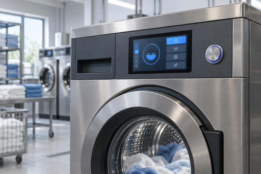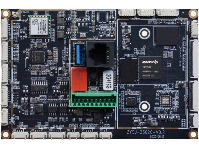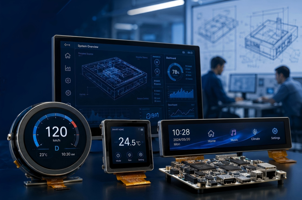
A custom TFT LCD display should solve a defined integration problem. It should not begin as an open-ended request to create a new panel size, resolution, or pixel architecture.
For many OEM projects, the practical route is to identify an existing TFT LCD module whose active area, resolution, interface, timing, optical behavior, and mechanical envelope are suitable. The project can then evaluate changes around that platform, including the touchscreen, cover glass, backlight, FPC, connector, controller board, firmware, bonding structure, and enclosure.
This distinction affects feasibility, development scope, documentation, tooling, validation, and lifecycle control. It also helps engineering teams compare proposals that may all be described as “custom displays” but involve very different work.
What Is a Custom TFT LCD Display?
A custom TFT LCD display is an existing display platform coordinated or modified to meet the requirements of a specific product. The scope can range from a different cover-glass drawing to a complete display, touch, controller-board, firmware, and mechanical assembly.
| Project Level | Typical Scope | Main Engineering Work |
|---|---|---|
| Standard module | An existing TFT LCD is used without a physical modification | Host compatibility, cable, power, backlight, firmware, touch, and mechanical validation |
| Configured module | An existing LCD is combined with an available touch, cover, cable, or controller configuration | Configuration selection, drawings, drivers, assembly, and complete sample testing |
| Semi-custom display | The core LCD remains while surrounding parts are adapted | Cover glass, touch, backlight, FPC, connector, bonding, firmware, tooling, and mechanical coordination |
| Integrated display system | An existing LCD is supplied with a controller or computing board and product-specific integration | Display output, panel driver, touch input, power, backlight, software, cables, and enclosure validation |
| New panel-platform request | The required size, active matrix, or resolution is unavailable from an existing platform | Separate feasibility, volume, investment, qualification, supply, and lifecycle assessment |
RJY Display’s practical customization route begins with an existing display module. It should not be interpreted as unrestricted development of any arbitrary TFT LCD size, resolution, active area, or panel architecture.
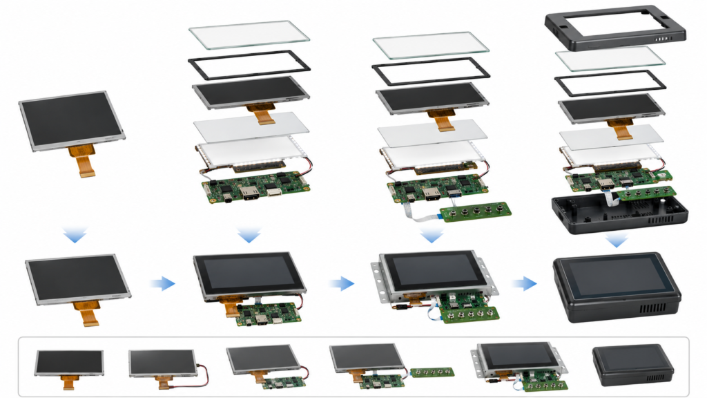
When Is Customization Actually Necessary?
Customization is not automatically better than a standard module. If an existing display meets the mandatory electrical, optical, mechanical, touch, environmental, software, and lifecycle requirements, using it unchanged may reduce project scope.
Customization becomes relevant when a documented requirement cannot be satisfied by the preferred standard configuration.
| Observed Problem | Possible Project Response | Evidence Needed |
|---|---|---|
| The front design requires a different outline or printed border | Custom cover glass based on the selected LCD and touch structure | Cover drawing, materials, tolerances, appearance criteria, bonding area, and enclosure CAD |
| The display FPC conflicts with the PCB or enclosure | Evaluate an alternate module, adapter, cable, or feasible FPC change | LCD pinout, connector definition, PCB layout, signal requirements, and mechanical envelope |
| The finished display is difficult to read in its intended environment | Review backlight, cover stack, surface treatment, bonding, UI, and installation | Ambient-light condition, viewing direction, optical stack, power budget, and physical sample test |
| The host does not implement the panel interface | Select another LCD, revise the host, or evaluate an active controller or bridge | Board revision, schematic information, supported output modes, panel timing, pinout, and firmware |
| The required touch behavior is not supported | Review the sensor, controller, firmware, cover glass, grounding, and host driver | Input tool, contact count, environment, controller data, cover structure, and acceptance test |
| The module does not fit the assembly | Compare another existing platform before starting mechanical customization | Complete display drawing, tolerance stack, PCB, cover, cable, and enclosure CAD |
A requirement should be classified as mandatory, preferred, or negotiable. This prevents a cosmetic preference from creating tooling or firmware work that provides no useful product benefit.
Build the Requirement Baseline Before Selecting the Display
A useful custom TFT LCD review begins with the product rather than a generic screen specification.
| Requirement Area | Questions to Resolve |
|---|---|
| Application | What does the product do, who uses it, and which information or controls must remain available? |
| Display geometry | What active area, viewing area, outline, orientation, thickness, and rear-component envelope can the product accept? |
| User interface | What resolution, physical text size, graphics workload, languages, warnings, and system states are required? |
| Host platform | Which MCU, application processor, computing module, controller board, or video source will drive the display? |
| Touch input | Which finger, glove, stylus, contact count, gesture, moisture, and false-touch behavior must be validated? |
| Viewing environment | What ambient light, viewing distance, mounting angle, dimming, reflection, and temperature conditions apply? |
| Mechanical assembly | Where are the bezel, cover, supports, adhesive, FPC, connector, PCB, fasteners, cables, and heat sources? |
| Lifecycle | What prototype, pilot, production, revision-control, change-notification, and replacement processes are required? |
Provide representative UI artwork and drawings early. A diagonal size alone does not define the physical image, module outline, visible opening, pixel workload, or touch target geometry.
Select the Existing TFT LCD Platform
The base module determines which later changes are realistic. Use the current controlled datasheet and mechanical drawing rather than a product-page summary.
Compare candidates using:
- Exact model, revision, driver IC, and current supply status
- Active area, viewing area, module outline, thickness, and native orientation
- Resolution, pixel format, native timing, and initialization requirements
- Interface, electrical levels, lanes or channels, pinout, and connector
- Backlight electrical requirements, enable, dimming, and thermal behavior
- FPC position, contact direction, stiffener, components, and safe bend region
- Optical characteristics and intended viewing conditions
- Operating and storage limits documented for the exact configuration
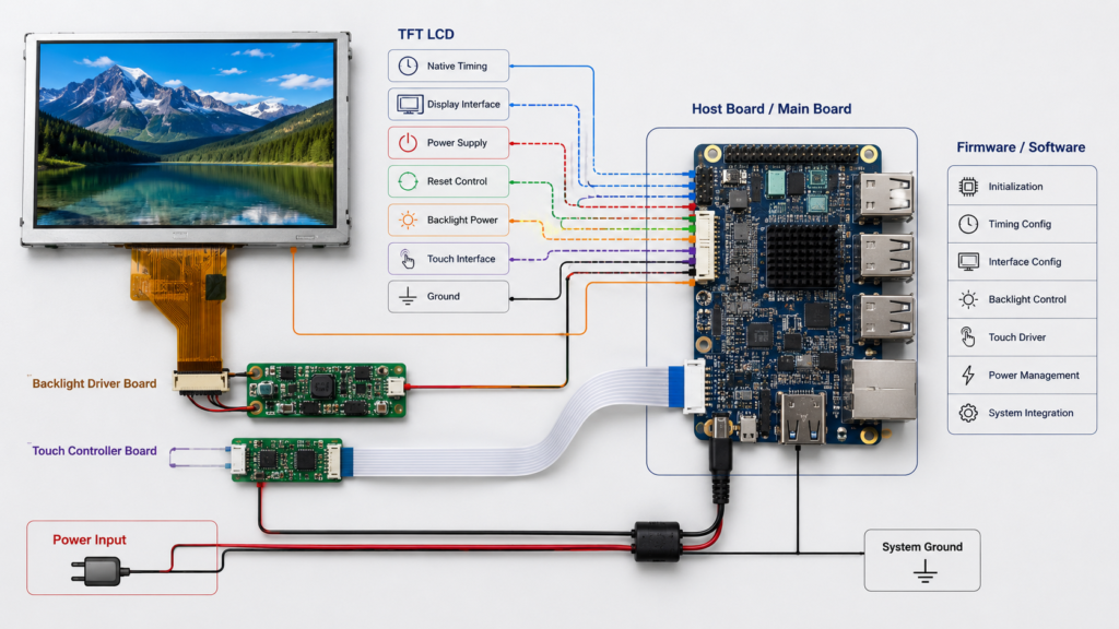
NXP’s embedded display-system example shows that a functioning LCD path requires coordinated native timing, signal polarity, power, reset, backlight control, interface clocks, and a panel-specific driver.[1] A matching resolution or interface label is therefore not enough to approve a base module.
Use the TFT LCD module selection guide for a deeper candidate review, then browse the current display module portfolio for existing platforms.
Customize the Touchscreen and Cover Glass Together
The touch sensor, touch controller, cover glass, bonding structure, display, host driver, grounding, and enclosure form one input system. A change to the front lens can alter the touch design even when the LCD remains unchanged.
| Touch or Cover Area | What to Define |
|---|---|
| Touch technology | Projected capacitive, resistive, or another supported input configuration |
| Touch controller | Exact controller, firmware, host interface, voltage, reset, interrupt, contacts, and driver |
| Input tools | Bare finger, specified glove, passive stylus, active stylus, or pressure-based input |
| Cover glass | Outline, thickness, opening, printed border, material, edge details, surface requirements, and adhesive area |
| Bonding | Air-gap or bonded structure, adhesive, alignment, appearance, tolerances, and rework requirements |
| Software behavior | Coordinate range, origin, scaling, rotation, display association, sleep, wake, and recovery |
| Environment | Moisture, cleaning, metal structures, electrical noise, edge operation, and false-touch criteria |
Microchip describes capacitive-touch sensor development as a combined mechanical and electrical design problem and specifically includes touch-cover effects within the design process.[2] This means that a custom cover glass should not be released independently of the sensor-controller review.
On Android systems, touch configuration may also control display association, calibration, and orientation-aware coordinate mapping.[3] Validate the approved controller firmware and host software with the final rotation, cover glass, bezel, grounding, and enclosure.
For detailed touch selection, see the TFT LCD module with touch screen guide.
Customize the Backlight From an Optical and Power Requirement
A backlight request should begin with the finished product’s viewing requirement. The highest available brightness is not automatically the correct target.
Review:
- Required ambient-light and viewing conditions
- LCD, polarizer, touch, bonding, cover-glass, and surface-treatment stack
- LED configuration and backlight electrical data
- Available driver circuit, current, enable signal, and dimming method
- Power budget and operating states
- Local heating and finished-enclosure temperature
- Low-level dimming behavior and application control
- Appearance and consistency criteria for the approved sample
Do not infer sunlight readability, outdoor suitability, thermal performance, or operating lifetime from a nominal brightness value. These conclusions require configuration-specific data and finished-product validation.
Coordinate the Interface, FPC, Connector, and Host Board
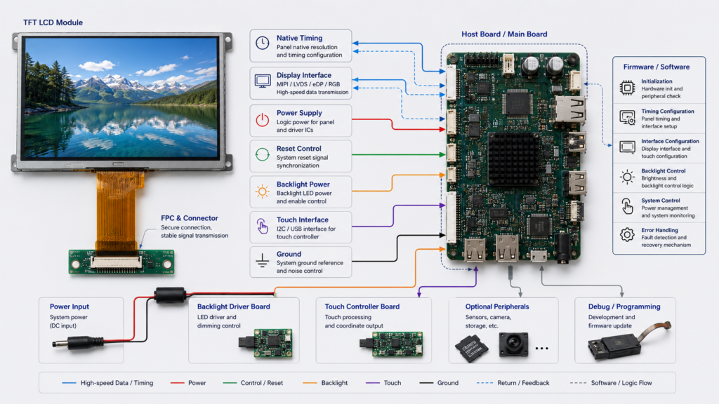
Interface customization is not simply changing the printed name beside a connector. The LCD and host must agree electrically, logically, mechanically, and in software.
| Integration Area | Items to Confirm |
|---|---|
| Display interface | RGB, MIPI DSI, LVDS, eDP, SPI, or another implemented route and its complete configuration |
| Native timing | Active dimensions, pixel clock, synchronization, porches, refresh range, format, and polarity |
| FPC pin definition | Every display, control, power, ground, reset, backlight, and touch connection |
| Connector | Part number, pitch, contact side, height, insertion direction, mating part, and access |
| FPC mechanics | Exit direction, length, stiffener, bend region, component envelope, retention, and assembly sequence |
| High-speed path | Board, connector, FPC, cable, grounding, return path, and signal-integrity review where applicable |
| Software | Panel driver, initialization, regulators, GPIOs, orientation, sleep, wake, and error recovery |
MIPI Alliance defines MIPI DSI as a high-speed serial interface between a host processor and a display module.[4] A common DSI label still does not prove that a host and panel share the required lanes, operating mode, timing, commands, power sequence, connector, or software support.
A custom FPC can reroute compatible signals or improve mechanical integration. It cannot create an absent display controller, add unsupported lanes, correct incompatible voltage levels, or replace missing panel firmware.
Use the LCD display interface guide for cross-interface background and the custom MIPI TFT LCD guide for DSI-specific integration.
Define Controller-Board and Firmware Responsibilities
A controller or computing board should be evaluated at board level. A processor datasheet can list interfaces that the finished PCB does not expose or that the current software image does not support.
Record:
- Exact board model, memory configuration, and hardware revision
- Implemented display output and connector
- Supported native timing and panel configuration
- Panel power, reset, enable, and backlight circuits
- Touch input and driver path
- Android, Linux, RTOS, MCU SDK, kernel, BSP, or bootloader version
- Panel-driver and initialization deliverables
- Source, binary, configuration, build, and ownership boundaries
- Update, recovery, sleep, wake, and interrupted-power behavior
“Custom firmware” is not an unlimited deliverable. A valid scope identifies the board, LCD, touch controller, software platform, version, required behavior, deliverables, ownership, and acceptance tests.
For Android projects, follow the guide to match a TFT LCD module with an Android control board. Current board-level product paths are available in Computing Modules.
Coordinate the Mechanical Structure Before Tooling
The LCD drawing, cover drawing, touch sensor, FPC, PCB, cable, supports, adhesive, fasteners, and enclosure CAD should be reviewed as one tolerance stack.
| Mechanical Item | Review Requirement |
|---|---|
| Active and viewing areas | Alignment with the bezel opening, cover printing, touch area, and UI |
| Module envelope | LCD glass, backlight, frame, adhesive, FPC, stiffener, and rear components |
| Support and retention | Approved support, adhesive, bracket, and fastener regions without localized glass loading |
| Cable path | FPC reach, bend, connector access, retention, heat, moving parts, and assembly sequence |
| Cover and touch alignment | Opening, printed border, adhesive, datum structure, and accumulated tolerances |
| Service access | Connector operation, inspection, replacement, and protection of the display assembly |
Do not release the enclosure around nominal display dimensions alone. Use the controlled drawing and include maximum material conditions and assembly tolerances where applicable.
Use a Controlled Custom Display Development Process
| Stage | Required Output | Approval Question |
|---|---|---|
| Requirement definition | Mandatory, preferred, and negotiable product requirements | Does the specification describe the product and acceptance conditions? |
| Base-module selection | Candidate datasheets, drawings, compatibility review, and open issues | Is an existing LCD platform technically suitable? |
| Feasibility review | Customization boundary, responsibilities, tooling, software, test plan, and commercial assumptions | Is each requested change feasible and controlled? |
| Drawing and configuration release | LCD, touch, cover, FPC, connector, board, firmware, and mechanical definitions | Are all parties reviewing the same revision? |
| Sample build | Traceable hardware and software samples with deviations recorded | Does the sample represent the proposed production configuration? |
| System validation | Test results against agreed acceptance criteria | Does the complete product work under the required conditions? |
| Production release | Approved configuration, inspection criteria, packaging, revision control, and open-item closure | Is the released product the same configuration that was validated? |
Do not begin tooling merely because a display can show an image on an evaluation board. Electrical operation is only one part of the approval.
Validate the Complete Custom TFT LCD Sample
| Validation Area | Minimum Review |
|---|---|
| Identity and documentation | LCD model, driver IC, drawing, touch controller, board revision, firmware, cables, and deviations |
| Display image | Native timing, full-screen patterns, orientation, colors, UI screens, startup, sleep, wake, and restart |
| Touch input | Coordinates, edges, rotation, required input tools, cover glass, noise, moisture criteria, sleep, and wake |
| Optical performance | Required UI, ambient light, viewing directions, cover stack, reflections, dimming, and appearance |
| Power and backlight | Startup, normal operation, enable, dimming, shutdown, interrupted power, and enclosure temperature |
| Software | Bootloader, panel driver, BSP or SDK, application, update, recovery, and error states |
| Mechanical assembly | Alignment, support, FPC routing, connector access, adhesive, tolerance stack, retention, and service procedure |
| Environment | Application-defined temperature, cleaning, moisture, mechanical, ambient-light, and electrical conditions |
| Configuration control | Complete approved bill of materials, drawings, firmware, software image, test record, and unresolved issues |
Approve the complete configuration rather than only the LCD model. A later change to the panel driver IC, touch controller, cover glass, FPC, board revision, firmware, adhesive, backlight, cable, or enclosure may require partial revalidation.
Prepare a Complete Custom TFT LCD RFQ
Provide:
- Target product, users, workflow, and destination markets
- Required active area, resolution, orientation, outline, and mechanical envelope
- Representative full-scale UI artwork and graphics workload
- Exact MCU, processor, controller board, computing module, or video source
- Board revision, implemented display output, connector, and software platform
- Touch technology, controller, input tools, contact count, and environmental requirements
- Cover-glass drawing, material, thickness, printing, edge, opening, and surface requirements
- Backlight, dimming, power, ambient-light, and viewing requirements
- FPC direction, connector position, PCB layout, cable, and assembly constraints
- Firmware, driver, BSP, bootloader, update, and recovery scope
- Enclosure CAD and tolerance information
- Required tests, standards, reports, declarations, and responsible parties
- Prototype, pilot, production, and expected annual quantities
- Lifecycle, revision, change-notification, and replacement expectations
- Existing display documentation when replacing another module
For cost-specific preparation, see the custom TFT LCD display pricing guide.
Request a Custom TFT LCD Engineering Review
RJY Display can review an existing TFT LCD platform against your touch, cover-glass, backlight, FPC, interface, controller-board, firmware, power, optical, and mechanical requirements.
Browse current display modules, review RJY Display’s custom solution scope, or send your display, board, UI, and enclosure documents for engineering review.
FAQ
What is a custom TFT LCD display?
A custom TFT LCD display is normally an existing display platform configured or modified for a specific product through areas such as touch, cover glass, backlight, FPC, interface, controller board, firmware, bonding, or mechanical structure.
Can RJY Display develop any new LCD size or resolution?
No. The practical customization route begins with an existing display module. A request for an unavailable size, active matrix, resolution, or new panel architecture requires a separate feasibility review and should not be assumed to be available.
Which parts of a TFT LCD module can be customized?
Depending on the selected base module and project feasibility, the work can include cover glass, touchscreen, bonding, backlight, FPC, connector, interface coordination, controller board, firmware, and mechanical structure.
Does changing the FPC make any LCD compatible with my board?
No. An FPC can route compatible signals and improve mechanical fit, but it cannot add a missing display controller, create unsupported lanes, correct incompatible voltage or timing, or replace absent panel firmware.
What should be tested on a custom display sample?
Test the documented display timing and image, touch behavior, cover stack, optical performance, power and backlight, firmware, startup and recovery, application workload, mechanical assembly, required environmental conditions, and complete configuration identity.
What information is needed for a custom TFT LCD quotation?
Provide the application, display geometry, resolution, UI artwork, host board, interface, touch and cover-glass requirements, backlight and power needs, FPC and connector constraints, firmware scope, enclosure drawings, validation requirements, quantities, and lifecycle expectations.
References
- NXP Semiconductors, “AN12940: Use Case of RT1170 LCD Display System Based on MIPI DSI.” https://www.nxp.com/docs/en/application-note/AN12940.pdf
- Microchip Technology, “AN2934: Capacitive Touch Sensor Design,” July 24, 2020. https://www.microchip.com/en-us/application-notes/an2934
- Android Open Source Project, “Touch Devices.” https://source.android.com/docs/core/interaction/input/touch-devices
- MIPI Alliance, “MIPI Display Serial Interface (MIPI DSI).” https://www.mipi.org/specifications/dsi