Facing a bottleneck in your Embedded Display Project?
Don’t let complex integration or supply chain issues slow your time-to-market. Book a free consultation with the RJY expert team for tailored design and manufacturing support.

An HDMI-to-MIPI controller board can connect an HDMI video source to a MIPI DSI LCD panel, but the presence of the correct connector is not enough to confirm compatibility. Two panels may both use a 40-pin FPC connector and four MIPI data lanes while requiring different pin assignments, video timing, initialization commands, power rails, reset sequences, or backlight circuits.
For an engineering project, the correct question is therefore not simply, “Does this panel use MIPI?” It is, “Can this controller board generate the exact electrical, timing, firmware, and power conditions required by this panel?”
This guide explains how to evaluate an HDMI to MIPI controller board before ordering a sample or connecting an unfamiliar LCD panel.
An HDMI-to-MIPI controller board receives video from an HDMI source and converts it into a MIPI Display Serial Interface signal suitable for a compatible LCD module. MIPI DSI is a high-speed interface defined for communication between a host processor and a display module.[1]
A simplified signal path looks like this:
HDMI source → HDMI receiver or bridge circuit → MIPI DSI transmitter → LCD driver IC and panel
The complete display system normally includes additional paths that should not be confused with video conversion:
This is why an HDMI-to-MIPI board should be treated as part of a display system rather than as a passive connector adapter.
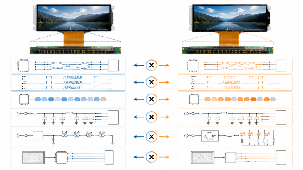
A connector description communicates only a small portion of the information required to drive a panel. “40-pin” identifies the number of contacts, not the function assigned to each contact. Similarly, “4-lane MIPI” does not establish the required lane rate, pixel format, video timing, operating mode, or initialization sequence.
MIPI DSI commonly uses a clock lane and one or more data lanes. An NXP application note describes D-PHY-based DSI configurations with one clock lane and up to four data lanes, while also distinguishing between command-mode and video-mode panels.[2] The controller and panel must agree on the relevant implementation details.
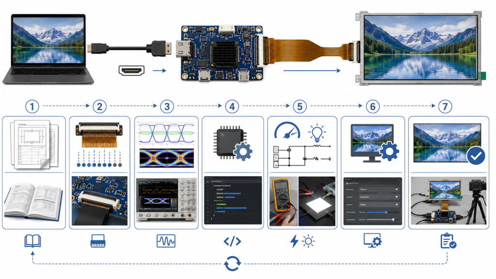
Before approving compatibility, review the following areas as one system.
“MIPI” is not a complete panel-interface description. MIPI specifications cover several functions, including display, camera, touch, control, and other device interfaces. An LCD display input should normally be identified specifically as MIPI DSI or MIPI DSI-2, not merely “MIPI.”
The panel datasheet should identify:
Do not confuse MIPI DSI display signals with MIPI CSI camera signals. They serve different data paths and are not interchangeable.
A controller board advertised as a four-lane MIPI board should not automatically be assumed to support every one-, two-, three-, or four-lane panel. The bridge hardware may have a specific lane capability, while its firmware may be configured for a narrower set of lane arrangements.
Confirm all of the following:
| Lane Item | Information Needed from the Panel | Information Needed from the Board |
|---|---|---|
| Data-lane count | Required number of active lanes | Supported and firmware-configurable lane counts |
| Clock lane | Clock-lane pins and electrical requirements | Clock-lane output and connector mapping |
| Lane polarity | Positive and negative pin assignment | Whether polarity follows the same mapping or can be changed |
| Lane order | Location of data lanes on the FPC | Physical routing and any supported lane remapping |
| Per-lane data rate | Required operating range | Bridge and firmware output range |
If the panel requires two data lanes but the board is configured for four, compatibility depends on whether the hardware and firmware can generate the panel’s required two-lane stream. It should be verified rather than inferred.
Resolution is only the visible pixel matrix. A controller also needs the complete video timing, including horizontal and vertical blanking intervals, synchronization widths, front porch, back porch, pixel clock, refresh rate, and signal polarity where applicable.
For example, an 800 × 1280 portrait panel and a 1280 × 800 landscape panel contain the same number of active pixels, but that does not make them electrically or logically equivalent. Their timing definitions, scan direction, initialization, and expected input orientation may differ.
The minimum compatibility review should include:
| Parameter | Why It Matters | Possible Symptom When Incorrect |
|---|---|---|
| Active resolution | Defines the visible pixel matrix | No image, cropped image, or unsupported mode |
| Refresh rate | Affects pixel clock and required link bandwidth | Unstable image or no synchronization |
| Horizontal and vertical timing | Defines how each frame is transmitted | Shifted, rolling, duplicated, or blank image |
| Pixel format | Controls how color data is packed | Incorrect colors or no image |
| Lane data rate | Must carry the required pixel stream | Artifacts, instability, or link failure |
A useful initial bandwidth check is based on pixel clock, bits per pixel, and the number of data lanes. Texas Instruments gives the basic relationship as:
Approximate data rate per lane = pixel clock × bits per pixel ÷ number of lanes[3]
This is a preliminary engineering calculation, not a complete qualification. Blanking, packet overhead, bridge limitations, and the panel’s permitted lane-rate range still have to be considered.
A controller board’s stated maximum resolution therefore indicates an upper capability boundary; it does not prove support for every timing below that resolution.
MIPI DSI panels may operate in video mode or command mode. In video mode, the host sends a real-time pixel stream. In command mode, the system communicates with the display using commands and data transactions, often with local display memory involved.[2]
Some panels must first receive a manufacturer-specific initialization sequence before video transmission begins. The sequence may configure the driver IC, pixel format, orientation, power behavior, gamma settings, timing, sleep state, or display enable state.
NXP’s MIPI DSI driver documentation reflects this distinction: the DSI peripheral is initialized, D-PHY timing is configured, command transfers can be performed, and video mode may then be started with the required DPI configuration.[4]
Before matching a controller board, determine whether the panel requires:
If the panel supplier cannot provide the initialization code or a proven reference design, firmware adaptation can become significantly more difficult.
Never connect a panel based only on connector pitch and pin count. The complete pin definition must be compared line by line.
A 40-pin, 0.5 mm-pitch connector might carry a combination of:
The FPC contact side, insertion direction, connector orientation, and cable routing must also match the mechanical design. A mirrored pin sequence can place power on a signal pin even when the connector appears to fit physically.
MIPI DSI describes the display communication interface; it does not eliminate panel-specific power requirements. The LCD may require several logic or analog rails, and the driver IC may specify a defined order for applying power, reset, initialization, sleep-out, display-on, and backlight enable.
In NXP’s example of bringing up a DSI LCD, the implementation includes configuring panel power, reset, backlight GPIO, timing parameters, and signal polarity before normal operation.[2]
Review these items separately:
A working backlight does not prove that MIPI communication is working. Conversely, a correctly initialized LCD may remain visually dark if the backlight circuit is not enabled.
The HDMI source must supply a video mode that the controller board can receive and translate into the panel’s required timing. A laptop, PC, Raspberry Pi, or embedded computer may select its output mode based on display identification, operating-system configuration, or a manually defined mode.
Before testing, confirm:
Do not assume that an HDMI-to-MIPI board automatically scales, rotates, or converts every source mode. These functions should be confirmed for the actual firmware.
Converting HDMI video into MIPI DSI does not automatically convert or enable touch input. A capacitive touch panel may use USB, I2C, or another connection, while its controller may require host-side driver and firmware support.
MIPI also maintains a separate family of specifications for touch integration, illustrating that display transmission and touch input are distinct system functions.[5]
For an HDMI-source project, verify:
For more detail about separated HDMI video and touch paths, see RJY Display’s guide to Android touch and HDMI touch integration.
RJY Display’s current product page identifies the RJY-HDMI-MIPI-V1 as an HDMI-to-MIPI controller board using an LT6911C main chip. The published configuration describes a four-lane MIPI LCD connection, a 40-pin 0.5 mm FPC connector, and support for resolutions up to 1920 × 1200.[6]
| Published Board Item | What It Establishes | What Still Requires Confirmation |
|---|---|---|
| HDMI-to-MIPI function | The board bridges an HDMI source to a MIPI LCD output | Supported HDMI input modes and panel-specific firmware |
| MIPI four-lane LCD output | The stated output configuration uses four MIPI data lanes | Panel lane rate, lane order, polarity, and mode |
| 40-pin, 0.5 mm FPC connector | The physical connector format | Complete pin-to-pin compatibility and FPC orientation |
| Maximum resolution up to 1920 × 1200 | A published resolution ceiling | Exact resolution timing, refresh rate, and pixel format |
| LED backlight support | The board includes backlight-related capability | Compatibility with the panel’s actual LED string and dimming requirements |
These specifications are useful for initial screening, but a panel should not be declared compatible until its datasheet, pin definition, initialization information, timing, and power requirements have been reviewed.
Not enough information is available to answer from those three specifications alone.
The panel passes an initial screening because its resolution is below the board’s published maximum, and its stated lane count and connector format appear relevant. However, engineering confirmation still requires:
Compatibility should be confirmed against these items before a sample board is connected to the panel.
For background on panel timing, FPC, backlight, and controller-board integration, read Structure and Driving Principle of TFT Liquid Crystal Display.
| Symptom | Likely Areas to Review |
|---|---|
| No backlight and no image | Board power, panel power rails, enable signals, connector orientation, and protection state |
| Backlight on but no image | DSI initialization, reset sequence, timing, lane configuration, firmware, and panel enable |
| Image shifted or rolling | Horizontal and vertical timing, pixel clock, sync settings, and refresh rate |
| Wrong colors | Pixel format, color order, bit depth, and driver-IC configuration |
| Intermittent artifacts | Lane rate, signal integrity, FPC quality, grounding, power stability, and timing margin |
| Video works but touch does not | Touch interface, host driver, USB or I2C connection, power, mapping, and orientation |
| Correct image in the wrong orientation | Source rotation, panel scan configuration, initialization commands, and bridge firmware capability |
Providing complete documentation before sampling reduces unnecessary trial-and-error. Prepare:
If the original datasheet or initialization sequence is unavailable, identify that limitation at the beginning of the review. A photograph and nominal resolution alone are rarely sufficient for reliable MIPI panel adaptation.
RJY Display can review your MIPI LCD panel, HDMI source, connector, timing, backlight, touch, and firmware requirements before sample selection. Compatibility is evaluated for the actual panel and controller-board configuration rather than inferred from connector size alone.
View the RJY HDMI-to-MIPI Controller Board or send your panel datasheet and project requirements.
No. The same pin count and connector pitch do not guarantee the same pin definition. Power, ground, MIPI lanes, reset, backlight, touch, and control signals must be compared pin by pin before connection.
Only if the bridge hardware and firmware support the panel’s two-lane configuration, timing, pixel format, and required lane rate. Four-lane capability alone does not confirm two-lane compatibility.
No. Maximum resolution is only an initial capability boundary. The exact pixel clock, blanking intervals, refresh rate, DSI mode, pixel format, lane rate, initialization sequence, and firmware must also match.
No. Touch normally uses a separate controller and communication path such as USB or I2C. The touch interface, host driver, power, coordinate mapping, and orientation must be reviewed separately.
The review should include the original panel datasheet, complete FPC pin definition, timing table, driver IC, initialization commands, power sequence, backlight specification, touch-controller details, and information about the HDMI source.
No. Those specifications are useful for initial screening, but approval still requires the panel pinout, timing, operating mode, initialization sequence, power rails, backlight requirements, firmware support, and source-output configuration.
Share your display size, resolution, interface, brightness, touch requirement, controller board requirement, and application environment.
Continue reading related display technology guides and application references.
Talk to RJY’s engineering team for display matching, controller board review, and customization discussion.









