A display integration can fail even when each team delivers the part it was asked to provide. The host team may configure one video timing while the panel supplier specifies another. The touch supplier may tune a prototype before the final cover and grounding scheme are available. Procurement may approve a replacement module without knowing which firmware and tests depend on the original.
TFT LCD design and integration depends on clear agreements between teams: what each interface must do, who owns it, how it will be checked, and what happens when it changes. This guide follows those agreements from product requirements through production release. It is for OEM engineers, program managers, and buyers coordinating a display project.
For display customization options, see the custom TFT LCD guide. For the physical assembly sequence, see the industrial touch screen assembly guide. Here the focus is the system handoff: how the display, host, software, power, enclosure, touch, and manufacturing teams prove that their work fits together.
Turn product needs into interface agreements
Begin with the result the user needs, then identify the teams that can affect it. For example, readable alarms require suitable graphics, an optical stack, a display, backlight control, and a test in the expected lighting. Touch accuracy depends on the sensor, cover, controller settings, coordinate mapping, and the electrical environment. No single drawing captures all of these dependencies.
An interface agreement is a controlled record shared by the teams on both sides of a boundary. It should identify the exact parts and revisions, define the inputs and outputs, name the owner and approver, and point to the evidence that will prove the match. The agreement may be a table in a system specification rather than a separate document. What matters is that both sides work from the same revision.
For the video boundary, the record can identify the panel input, connector and pinout, color format, timing limits, source configuration, and startup sequence. For touch, it can identify the controller interface, coordinate orientation, cover stack, tuning revision, and required behavior. For the mechanical boundary, it can identify the mounting drawing, tolerances, cable route, clearance, and load paths. The relevant details depend on the design.
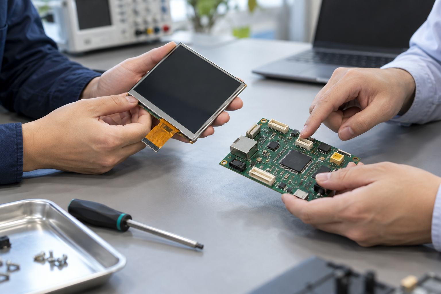
Document both sides of the boundary. A panel datasheet describes what the panel accepts; it does not, by itself, prove that the selected host produces it. A host capability list does not prove that a particular cable, board, and firmware configuration will work together. The agreement connects those claims to a test on the intended configuration.
Assign owners for each handoff
The same organization may fill several roles. Assign a named owner in the project record and a second party to accept each handoff. The following matrix is a starting point, not a claim about how every supplier divides responsibility.
| Boundary and owner | Handoff evidence | If the check fails |
|---|---|---|
| Panel supplier to host electrical team | Released part revision, pinout, supply and video timing limits; host configuration and measurements | Hold the interface approval; compare revisions and measure the signals before changing components |
| Host and software teams to system team | Firmware build, initialization settings, timing, reset and backlight control, with reproducible test results | Record the failing build and startup conditions; isolate the relevant configuration or hardware boundary |
| Touch supplier to mechanical and software teams | Cover and sensor stack, controller settings, communication interface, coordinate mapping and test results | Check the tested stack and grounding against the intended assembly; agree who owns tuning or software correction |
| Mechanical team to system test | Released enclosure and mounting drawing, tolerances, cable routing and representative assembled sample | Capture the interference or fit issue; revise the drawing and repeat affected assembly and function checks |
| Engineering to manufacturing and procurement | Approved bill of materials, drawings, software versions, sample, inspection criteria and change process | Hold release or shipment until the discrepancy is assessed and disposition is recorded |
Include third parties when they control a boundary. If one company supplies a panel and another supplies a bridge board, name who is responsible for proving the combination. A board advertised with the right interface still needs to match the exact panel and host. The HDMI-to-MIPI 호환성 가이드 shows the questions that arise for one conversion path.
Trace a requirement to a test: a worked example
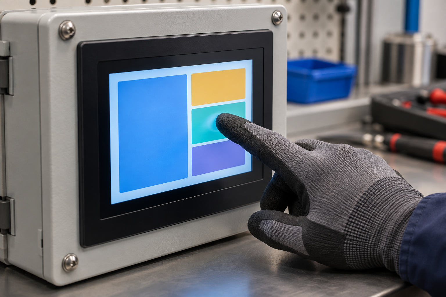
Consider an OEM developing a factory control terminal. The product team wants an operator wearing a specified glove to select controls accurately while the machine is running. The numbers and conditions below are illustrative project choices, not specifications or guarantees for a display.
| LCD 모델 및 개정 | Example |
|---|---|
| User need | An operator can select displayed controls while wearing the agreed glove. |
| System requirement | On the released assembly, each touch at nine defined test points registers within 5 mm of its intended point, in the agreed orientations and operating conditions. No touch may be missed or produce an unintended input during the test. |
| Dependencies | Cover and sensor revisions, touch controller and tuning, host software and coordinate mapping, enclosure grounding, power configuration, and glove definition. |
| Verification method | Use a representative assembled unit and the specified glove. Run the machine and display in the agreed operating state. Touch each defined point and record the intended and reported positions in the same physical screen coordinate system, plus any missed or unintended input. |
| Acceptance and owner | The system test team checks the distance between each intended and reported point against the agreed 5 mm limit and records any missed or unintended input. Engineering owns failure investigation; the touch and software owners support diagnosis. |
| Change trigger | A new cover thickness, controller setting, enclosure grounding path, or coordinate transform prompts an impact review and repeat of affected tests. |
The example exposes questions that a requirement such as “supports gloves” leaves unanswered: which glove, which points, what tolerance, which operating state, and which assembly revision? The team should also agree how many units and repetitions are needed, how to measure each point, and how to investigate a failed test. The test limit must come from the product’s usability and risk needs, not from this example.
Touch design involves the sensor, cover, shielding, and other electrical conditions.[1] In a project, link each dependency to its controlled drawing or configuration so the test remains reproducible.
Use review gates with evidence and exit criteria
Gates help the team decide when it has enough evidence to proceed. They do not replace engineering judgment, and the depth of evidence should match the product’s risk and obligations. Agree who can approve an exception and when it must be closed.
Gate 1: requirements and architecture
Before detailed design, approve the intended use conditions, measurable system requirements, proposed display and host path, major mechanical boundaries, and ownership matrix. List open assumptions and assign a closure date. Exit when each critical requirement has an owner and a planned verification method, and the teams have agreed on the current interface documents.
Gate 2: functional integration sample
Build a sample with identifiable panel, host, cable, software, and touch revisions. Establish a repeatable startup and show the planned image and touch functions. Exit when the critical interfaces have been checked against their agreements, results are recorded, and unresolved faults have owners and disposition. A bench sample can expose interface errors early, but its results do not establish final enclosure performance.
Gate 3: representative assembly qualification
Use an assembly representative of the intended production design. Run the agreed optical, touch, electrical, mechanical, and environmental tests at the conditions defined for the product. Exit when the acceptance criteria are met or documented exceptions have been approved by the responsible authority. Record the exact configuration and the tests performed, so the result can be assessed after a later change.
Gate 4: production release
Release the controlled bill of materials, drawings, software and settings, approved sample, inspection criteria, test instructions, and change-notification process. Confirm that the manufacturing team can identify the correct revisions and reproduce required checks. Exit when engineering, quality, manufacturing, and procurement accept their assigned handoffs. Open issues need an explicit disposition; do not treat a passed prototype as an automatic production approval.
Isolate faults at the boundaries
Start from the observed symptom and collect the configuration, operating condition, and sequence that produces it. Then choose a test that separates possible causes. Change one controlled variable at a time where practical, and record the result. The examples below are investigation paths, not automatic diagnoses.
| 관찰된 증상 | First boundary to examine | Evidence that helps isolate it |
|---|---|---|
| Backlight on, no image | Power, reset, initialization and host-to-panel video path | Measured rails and sequence, host output configuration, panel input requirements, and a repeatable startup log |
| Image appears with incorrect colors | Pixel format and mapping between source, any bridge, and panel | Solid-color and grayscale patterns, configuration records and the panel’s expected mapping |
| Touch drifts or reports false input when equipment runs | Touch stack, grounding, controller settings and nearby electrical activity | Results with the same assembly in documented operating states and a comparison of its actual stack and settings |
| Image or touch changes after enclosure assembly | Mechanical fit, cable routing and electrical connections | Photographs, fit measurements and controlled tests before and after assembly, without stressing exposed parts |
For example, LVDS bit mapping must agree at both ends. For the 24-bit mappings shown in TI’s note, JEIDA and VESA assign color bits differently.[2] A color error can have other causes too, so compare the actual configuration and test patterns before concluding that mapping is responsible. The LCD 인터페이스 가이드 provides a wider overview of interface choices.
If a known-good component is available, substitution can help isolate a fault only when it is compatible and the test conditions remain controlled. Record what changed. A successful swap identifies a useful direction for investigation; it does not, on its own, establish root cause.
Assess changes against the released configuration
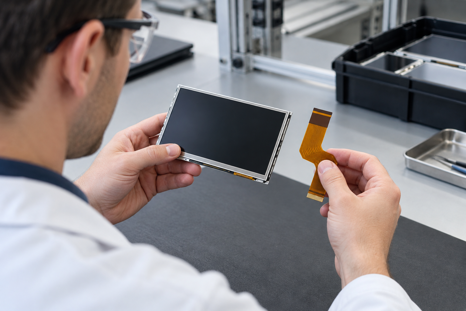
Once a configuration is qualified, any proposed change should be compared with the records used for that qualification. The owner identifies affected interfaces and requirements, selects tests, and obtains approval before the changed configuration enters production. The depth of review depends on the actual change and product risk.
- Panel replacement: Compare the approved mechanical, optical, electrical, timing, and backlight requirements, then assess software and test impacts. A similar size or resolution is not enough. See how to replace a discontinued TFT LCD module.
- Cover or bonding change: Review the stack drawing and touch tuning; repeat the affected optical, touch, mechanical, and environmental tests under the agreed plan.
- Host firmware change: Compare display initialization, timing, backlight control, and touch mapping with the released build; repeat startup, image, and touch tests as needed.
- Cable or routing change: Review pinout, mechanical fit, and signal behavior in the representative assembly; retest the affected interface and environmental conditions.
Record the proposed change, reason, affected part and revision, impact decision, required evidence, approvals, and effective date. Agree supplier notification and traceability terms in the purchase documents. Do not assume a supplier will manage changes in a particular way unless the parties have agreed it.
Prepare the supplier handoff
Share the system requirements and interface agreements, not only the desired screen size. Include the host and software environment, intended use conditions, enclosure constraints, touch requirements, expected volume, schedule, and any existing panel part number and revision. Identify which work the OEM expects the supplier to perform and who will validate the finished equipment.
RJY Display에 문의하십시오. to discuss a display project and, where applicable, controller-board or touch adaptation. Compatibility and support depend on the specific panel, host, software, and application. Agree the prototype configuration, responsibilities, and test evidence before using a sample as the basis for production.
자주 묻는 질문
Who owns display integration in an OEM project?
The OEM should assign a system owner who coordinates the boundaries and accepts the final evidence. The panel, host, touch, software, mechanical, and manufacturing owners remain responsible for their assigned deliverables. The exact split should be agreed with each supplier.
Does a working sample prove that the display is ready for production?
No. A working sample is useful evidence for its tested configuration and conditions. Production release also requires agreed qualification, controlled revisions, manufacturing instructions, inspection criteria, and a plan for changes.
What should be retested after a display change?
Assess the change against the released requirements and interfaces, then repeat the tests affected by the change. A replacement panel can affect electrical, software, optical, and mechanical behavior; the actual scope depends on the differences and the product’s risk.
What information helps diagnose a display integration fault?
Provide the exact part and software revisions, wiring or schematic, configuration, supply measurements, operating conditions, symptom, and steps to reproduce it. Include results from controlled tests and identify any recent change.