Enfrentando um gargalo no seu Projeto de Display Incorporado?
Não deixe que a integração complexa ou problemas na cadeia de abastecimento atrasem o seu tempo de colocação no mercado. Marque uma consulta gratuita com a equipa de especialistas da RJY para apoio personalizado em design e fabrico.
Guia do Conector do Cabo Flat do LCD: Como Compatibilizar FPC, Passo, Número de Pinos e Direção de Contato
Publicado:
18 min read
Atualizado:
Selecting an LCD module does not end with size, resolution and display interface. The flexible tail and its board-side connector must also fit the product. Two displays can both use MIPI DSI, LVDS, RGB or SPI and still have different connector pitches, pin counts, contact directions, cable thicknesses and pin assignments. Even two connectors that look identical can be electrically incompatible.
This is why an LCD ribbon cable connector should never be approved from a photograph or a short product listing. Engineers must compare the LCD drawing, FPC specification, connector datasheet and controller-board pinout. The mechanical fit is only one part of the decision. The power rails, grounds, backlight circuit, touch signals and high-speed data paths must also match.
This guide explains how to perform that comparison. It is intended for hardware engineers, product developers, sourcing teams and OEMs that need to connect a TFT LCD module to an existing or custom controller board.
What Is an LCD Ribbon Cable Connector?
An LCD ribbon cable connector is the board-mounted component that receives a flexible cable from the display module. In a compact embedded product, this connection often carries several functions at once:
LCD logic power and ground
Pixel data or high-speed differential signals
Clock, synchronization or command signals
Reset, enable and identification signals
Backlight power or control
Touchscreen power, data, interrupt and reset
The connector is not the same part as the flexible cable. It is also not the same as the LCD interface. A display interface defines how information moves between the host and the panel. The connector provides a physical and electrical path for those signals. Manufacturers can route the same interface through many different connector designs.
FPC, FFC and the board connector are different parts
FPC means flexible printed circuit. An FPC is made with patterned copper conductors on a flexible insulating film. Its traces can change direction, connect components, divide into branches and use several layers. A display manufacturer can design a custom FPC around the panel, driver IC, touchscreen and product enclosure.
FFC means flexible flat cable. It normally contains straight, parallel conductors laminated between insulating films. Standard FFC is useful when a design needs a simple point-to-point connection. The two ends can expose their contacts on the same side or on opposite sides.
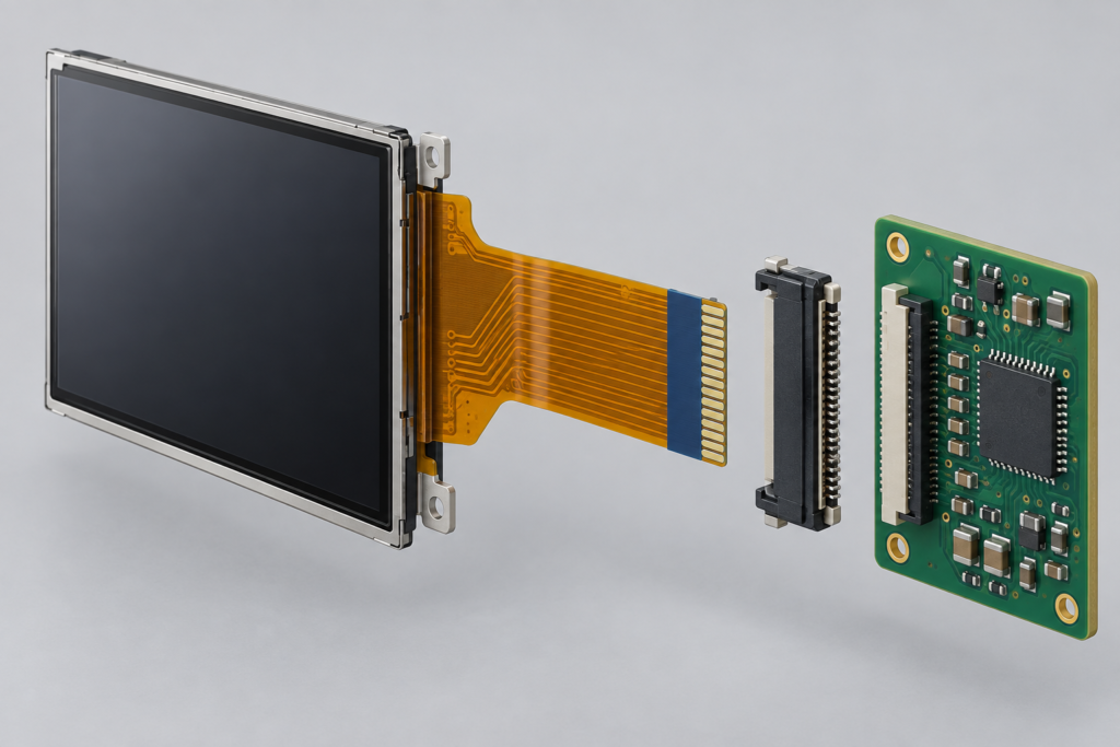
Exploded LCD module, FPC tail, connector and controller-board assembly
Um FPC/FFC connector is soldered to a printed circuit board. Its contacts press against the exposed copper pads on the cable. Connector makers offer many pitch, height, orientation, contact and locking options. For example, connector portfolios from Molex, Hirose, TE Connectivity and Amphenol include different top-contact, bottom-contact, dual-contact, ZIF, non-ZIF, vertical and right-angle configurations.123
Product listings sometimes use “FPC cable,” “FFC cable” and “ribbon cable” as broad terms. Do not depend on the name alone. Use the mechanical drawing and connector part number to identify the parts.
Why LCD Modules Use Flexible Connections
A rigid board-to-board connection would limit where engineers could place the display and controller board. A flexible tail can route through a narrow enclosure, fold around a support structure and absorb small assembly tolerances. It also reduces connector height and weight.
These benefits create design dependencies. The tail length affects board placement. The exit direction affects whether the tail reaches the connector without twisting. The bend area must stay clear of sharp housing edges. The stiffened contact end must match the connector slot. A good electrical match can still fail if the enclosure forces the cable into an unsuitable bend.
FPC vs. FFC: Which One Does an LCD Use?
Many bare TFT modules have an integrated FPC tail. The tail connects the panel driver area to the host board. It may also contain passive parts, test pads or a connector for a separate touchscreen. Its outline and trace routing are specific to the module.
Some display assemblies use a separate FFC between an LCD adapter board and the main controller board. This arrangement can simplify assembly or allow the same control platform to support several enclosure layouts.
FPC and FFC are not automatically interchangeable. Both may fit a connector if their pitch, conductor count, contact geometry, insertion-end thickness and material requirements match the connector specification. However, a custom FPC may have a different stiffener, copper thickness, impedance requirement or retention feature. Check the connector maker’s recommended cable dimensions instead of assuming that every flexible cable of the same width will fit.
Eight Specifications That Determine Connector Compatibility
A reliable comparison needs more than a visual check. At minimum, verify the following eight items.
Item
What to verify
Risk if it does not match
Pitch
Center-to-center spacing between adjacent contacts
The cable will not align with the connector contacts
Pin count
Number of active connector positions
The cable will not fit or required circuits will be missing
Contact side
Exposed conductors on one or both sides of the cable
The connector may press against insulation instead of copper
Contact direction
Top, bottom or dual contact inside the connector
A cable can enter mechanically but make no connection
Cable thickness
Specified thickness in the mating area
Poor retention, damaged contacts or inability to insert
Stiffener
Material, length and total insertion-end thickness
Unstable contact pressure or actuator damage
Lock type
Front flip, back flip, slider, stuffer, auto lock or non-ZIF
Assembly errors or weak retention
Pin definition
Function, voltage and direction of every circuit
No image, unstable operation or hardware damage
Connector families can share a nominal pitch but differ in height, insertion direction, supported FPC thickness, position count and actuator design. Hirose, for example, lists these as separate selection parameters rather than treating pitch as a complete specification.4 The exact connector part number is therefore the safest starting point.
How to Measure FPC Connector Pitch
Pitch is the distance from the center of one contact to the center of the next contact. It is not the full width of the cable, the width of one copper pad or the distance between the outside edges of two pads.
If a drawing is unavailable, you can make a preliminary estimate by measuring from the center of the first contact to the center of the last contact:
Pitch = center-to-center distance from the first contact to the last contact ÷ (number of contacts − 1)
For example, if the center of the first contact and the center of the twenty-first contact are 10 mm apart, the estimated pitch is 10 ÷ 20, or 0.5 mm. This method reduces the measurement error that occurs when a caliper is used across one very small gap.
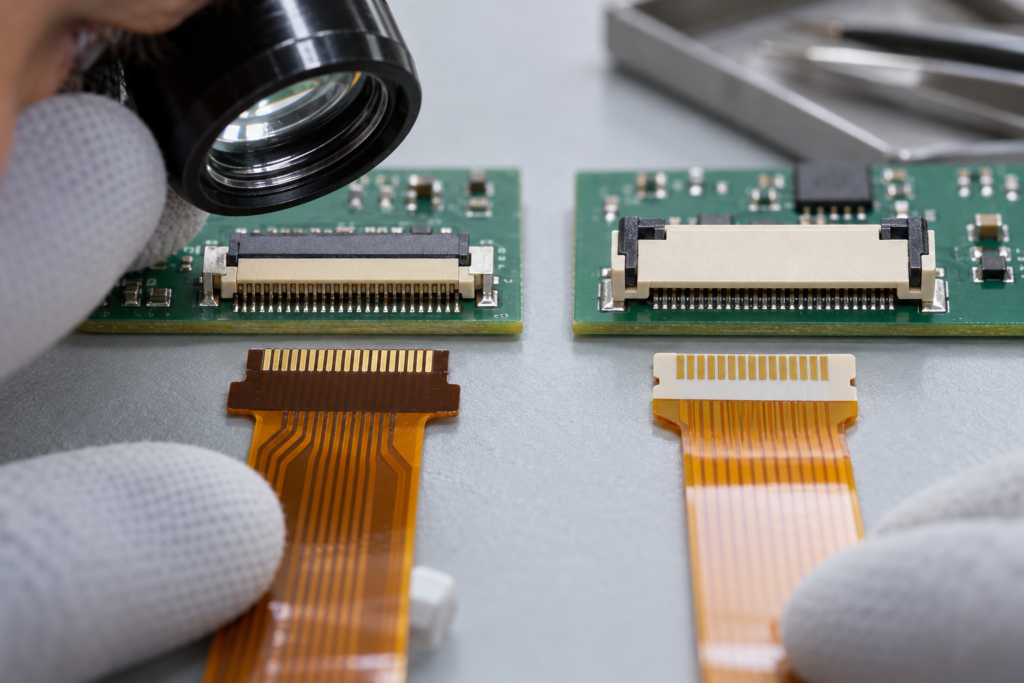
Engineering comparison of different FPC connector and cable-end configurations
Use this only to identify likely connector families. The approved value must come from the LCD drawing or connector datasheet. Connector makers offer many centerline values. TE Connectivity lists standard FPC solutions with several centerline spacings, while Amphenol lists a much wider range across its portfolio.35 A common value is not a universal value.
Top Contact vs. Bottom Contact
Top-contact and bottom-contact describe where the connector contacts meet the cable when the connector sits in its intended PCB orientation. The terms do not, by themselves, describe which way the visible copper on a loose cable should face. You must inspect both parts in their installed orientation.
Consider a right-angle connector mounted on the top side of a board. A top-contact connector may meet exposed pads that face away from the PCB. A bottom-contact connector may meet pads that face toward the PCB. A vertical connector uses a different insertion geometry. Dual-contact designs can contact either side, but they still have defined cable dimensions and pin numbering.
Do not infer contact direction from the color of the actuator or housing. Check the connector drawing. Molex, for example, sells otherwise similar 0.5 mm connector families with top, bottom and dual contact arrangements.1 Hirose also identifies contact orientation and insertion direction as separate properties.4
Same-side and opposite-side flexible cables
A simple FFC can expose both ends on the same side or on opposite sides. A same-side cable works when the two connectors expect the contacts to face the same relative direction. An opposite-side cable introduces a half twist in electrical orientation without physically twisting the cable.
For an integrated LCD FPC, the routing is fixed by the display design. If the board connector has the wrong contact direction, rotating the display or folding the tail may appear to solve the mechanical problem. It can also reverse the pin order or exceed the permitted bend condition. Confirm Pin 1 at both ends before changing cable orientation.
Pin Count Does Not Prove Pin Compatibility
A 40-pin display is not a standard electrical product class. One 40-pin module may use parallel RGB data. Another may use LVDS plus power and backlight control. A third may combine MIPI DSI, touch and several power rails. The connector can have the same pitch and the same number of positions while every important signal sits on a different pin.
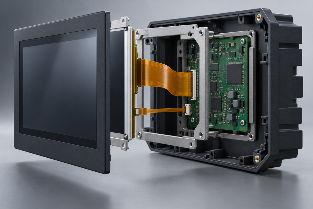
TFT LCD flexible cables routed inside an industrial HMI enclosure
Create a pin-to-pin comparison table before connecting a new panel. Include at least these columns:
Pin number on the LCD
LCD signal name and description
Required voltage or signal standard
Pin number on the controller board
Board signal name
Match, mismatch or action required
Compare every ground and power pin, not only the data lanes. A swapped ground and supply pin can damage the panel as soon as power is applied. Also check unused and reserved pins. A reserved pin on one panel may carry power or a control signal on another.
Read the drawing view before reading Pin 1
Mechanical drawings can show the connector from the mating face, solder side, component side, cable side or rear. A drawing can therefore appear mirrored when compared with the physical part. Find the view label and Pin 1 mark before recording the order. If either document is unclear, ask the supplier for a marked drawing rather than relying on a photograph.
The Display Interface Does Not Define the Connector
Terms such as MIPI, LVDS, RGB and SPI describe signal systems. They do not define one universal LCD connector or pinout.
MIPI DSI
A MIPI DSI module can use one, two or four data lanes. It can require several power rails, reset and enable signals, and a module-specific initialization sequence. Some modules include touch signals on the main FPC; others use a separate touch tail. The DSI lane count, lane mapping, operating mode and driver support must match in addition to the connector.
LVDS
LVDS panels can differ in channel count, bit depth, mapping, clock arrangement, power voltage, backlight circuit and control pins. The same connector shell does not confirm VESA or JEIDA mapping, nor does it confirm that a controller board can generate the required native timing.
Parallel RGB and MCU interfaces
Parallel displays may use different data widths and synchronization schemes. A connector must provide enough conductors, but the pin order remains module-specific. SPI or MCU-style modules can also differ in chip-select, data/command, reset, read and backlight connections.
HDMI is normally a board input
A bare TFT LCD module does not usually accept HDMI directly. An HDMI controller board receives the source signal, processes it and drives the panel through its native interface. Therefore, “HDMI display” may describe a finished assembly rather than the electrical interface on the LCD FPC. An HDMI-to-MIPI controller is an active, panel-dependent system, not a passive cable conversion.
Electrical Checks Beyond the Connector
After the mechanical connector matches, review the electrical system. This step determines whether the parts can operate safely together.
Power rails and I/O voltage
Identify every LCD supply rail, its tolerance and its power sequence. Do the same for I/O voltage. A board that uses the correct nominal connector can still expose the panel to the wrong logic level. Do not assume that all small TFT modules use one common voltage.
Circuito de retroiluminação
LCD logic power and LED backlight power are separate functions. Confirm the LED string arrangement, required current, forward-voltage range, connector pins, driver topology, enable polarity and dimming method. A controller board designed for one backlight load may not safely drive another.
Ground allocation and return paths
Ground pins can separate high-speed return paths, power returns and backlight current. Preserve the intended allocation. Do not reduce the number of grounds simply because they appear electrically common on a continuity test.
Differential pairs and high-speed routing
MIPI, LVDS and eDP connections need controlled routing. An adapter or extension changes trace length, impedance, loss, skew and return paths. A pin-for-pin adapter can therefore be logically correct but perform poorly at the required data rate. Keep differential pairs together, control geometry and validate the complete path on hardware.
Touchscreen signals
Some assemblies route touch power and I²C or USB signals through the same tail as the LCD. Others use a separate touch FPC. Confirm the touch-controller model, supply voltage, address or USB path, interrupt, reset and firmware support. Display operation does not prove that touch will work.
FPC Exit Direction and Enclosure Integration
The tail must reach the controller board without a sharp fold, permanent twist or collision with the housing. Review the FPC exit direction when the LCD is in its final orientation, not when it lies flat on a bench.
Define the routing with a mechanical drawing or 3D model. Mark the connector location, insertion direction, locking access and service clearance. Keep the dynamic bend area away from the stiffener and solder joints. Avoid pressing the FPC against a sharp metal edge. If the tail moves during normal use, treat it as a dynamic-flex application and request a cable designed for the required motion. A standard LCD tail should not be assumed to support repeated flexing.
Also plan the assembly sequence. A connector that is accessible before the front housing is installed may become impossible to lock after the LCD is bonded. Small front-flip and back-flip actuators need tool and finger clearance. A cable should enter squarely; using the latch to force a misaligned cable can damage both parts.
ZIF, LIF and Non-ZIF Connector Options
A ZIF connector uses an actuator so the cable can enter with very low insertion force. Closing the actuator creates contact pressure and retention. This design helps protect fine-pitch cable ends and supports controlled assembly.
A LIF ou non-ZIF connector depends more on friction during insertion. It can reduce part count or height in some designs, but the insertion force acts directly on the cable. Product terminology varies, so follow the connector datasheet.
Front-flip, back-flip, slider and stuffer describe different actuator actions. Auto-lock types can simplify assembly. Dual-contact types add routing flexibility. None is universally best. Select the mechanism according to board space, cable direction, operator access, vibration, expected mating cycles and service requirements. TE notes that its ZIF versions use an actuator and offer higher retention and more mating cycles in relevant product families.6
Common LCD Connector Matching Mistakes
Matching only the pin count. The connector and pin functions can still differ.
Estimating pitch from total cable width. Side margins and pad width make this unreliable.
Confusing contact direction with cable orientation. Inspect the installed connector and exposed pads together.
Ignoring the drawing view. A mirrored interpretation can reverse the pin order.
Treating the interface name as a pinout. MIPI, LVDS, RGB and SPI do not define one connector.
Checking the image but not the backlight. A lit screen does not prove that the LCD logic receives valid data.
Adding an extension without signal review. High-speed links can fail even when continuity is correct.
Buying from a photograph. Images rarely show cable thickness, contact geometry or exact pin mapping.
How to Validate an LCD and Connector Combination
1. Record the exact LCD model and revision
Use the full model code from the module label or approved bill of materials. A suffix can identify a different FPC, backlight, driver IC or touch configuration.
2. Obtain the current LCD datasheet and drawing
Collect the outline, FPC dimensions, pin definition, power requirements, interface timing, backlight data and initialization information. Confirm the document revision.
3. Identify the board-side connector
Use the full connector manufacturer and part number. Obtain its drawing and recommended PCB footprint. If the connector is already mounted, compare its markings and board records rather than identifying it by appearance alone.
4. Compare mechanical mating requirements
Check pitch, number of positions, contact side, contact direction, cable thickness, stiffener, insertion depth and retention features. Confirm that the cable does not bottom out before the pads reach the contacts.
5. Build a pin-to-pin map
Map every LCD pin to the intended board pin. Highlight power, ground, reserved pins, differential pairs, reset, enable, backlight and touch. Resolve every mismatch before applying power.
6. Review the interface and firmware path
Confirm native resolution, timing, lane count, mapping, pixel format, driver IC, initialization commands and host support. A passive pin adapter cannot correct incompatible display timing or missing firmware.
7. Review power and backlight limits
Check regulator capacity, sequencing, LED-driver range, dimming control and inrush behavior. Use the exact panel specification rather than a value copied from a similar display.
8. Inspect the enclosure route
Verify tail length, exit direction, bend condition, connector access and clearance. Include the touch tail and any bonding stack in the mechanical review.
9. Test with controlled power
Use current-limited supplies and a documented startup procedure during early validation. Monitor rails and check for abnormal current before enabling the backlight. Then verify repeated cold starts, warm restarts and sleep-and-wake cycles.
10. Freeze the approved configuration
Record the LCD revision, connector, PCB, cable or adapter, firmware, touchscreen and enclosure version. This prevents a later substitution from bypassing the compatibility review.
When Do You Need an Adapter Board or Custom FPC?
An adapter becomes useful when the selected LCD and host are electrically compatible but their physical connectors or pin order differ. Three common routes are available.
Replace the board connector
This can provide a compact final design when the PCB is still under development. The new footprint, contact direction and signal routing must fit the board. Replacing the connector does not solve interface, voltage or firmware differences.
Add an adapter board
An adapter board can remap pins, change connector orientation and add power, protection or backlight circuits. It is useful for prototypes and platform reuse. It also adds size, connectors and high-speed routing length. Validate signal integrity and mechanical retention.
Develop a custom FPC
A custom FPC can change tail length, shape, exit direction and connector-end pin routing. It can also combine LCD and touch connections in some architectures. The design needs electrical, mechanical and manufacturing review. Fine-pitch or high-speed signals can require controlled impedance, matched lengths and shielding. Tooling, sample validation and project volume also affect feasibility.
What RJY Display Can Review or Customize
RJY Display can evaluate the LCD connection as part of a complete module and controller-board project. Depending on the selected display platform and project requirements, the review can include:
FPC length, shape and exit direction
Connector position and pin-mapping coordination
LCD and touchscreen signal integration
Cover glass and touch-panel configuration
Requisitos de retroiluminação e visibilidade
Adapter-board or controller-board matching
Firmware coordination for the selected display path
Display-related enclosure and mounting coordination
These options are project-dependent. A connector adapter does not make every panel compatible with every host, and a custom connection does not remove the need to verify timing, voltage, backlight, firmware and mechanical conditions. The practical route often starts with an existing LCD module and adapts the surrounding connection and assembly.
Information to Send for an LCD Connection Review
Provide the following information when requesting a technical review:
Complete LCD model and revision
LCD datasheet, FPC drawing and pin definition
Controller-board or host-board model
Board schematic or display-connector pinout, where available
Connector manufacturer and part number
Display interface, resolution and timing requirements
Power-rail and backlight information
Touchscreen interface and controller requirements
Enclosure drawing, connector position and required cable route
Operating environment, sample quantity and estimated annual demand
If some documents are unavailable, send clear photographs of the labels, cable contacts and board connector together with measured dimensions. Photographs can support identification, but the final approval should still use controlled drawings and specifications.
Choose the Connection as Part of the Display System
An LCD ribbon cable is a small part with system-level consequences. Pitch and pin count determine whether parts align, but contact direction, cable thickness and lock type determine whether the connection is mechanically reliable. The pin definition, power design, backlight circuit, signal routing and firmware determine whether the display can operate.
Approve these items as one configuration. Do not treat the connector as an accessory that can be selected after the display and controller board are fixed.
Can two LCDs with the same pin count use the same connector?
They may fit the same connector, but that does not prove electrical compatibility. Compare pitch, contact direction, cable thickness and the function and voltage of every pin. Also verify the display interface, timing, backlight and firmware.
What does 0.5 mm pitch mean on an FPC connector?
It means the center of one contact is 0.5 mm from the center of the next contact. It does not define the pin count, connector height, contact direction, cable thickness or pin assignment.
How can I identify a top-contact or bottom-contact connector?
Use the connector part number and mechanical drawing. The drawing shows where the contacts meet the cable in the installed PCB orientation. Do not identify contact direction only from housing color or a product photograph.
Are FPC and FFC interchangeable?
Not automatically. A connector may accept both when their mating dimensions meet its specification. The pitch, contact count, exposed-pad arrangement, thickness, stiffener and retention features must match.
Can an LCD ribbon cable be extended?
An extension may be possible, but it changes mechanical routing and electrical performance. High-speed interfaces need special attention to impedance, loss, skew and return paths. Validate the complete display link at the required data rate.
Can a custom FPC change the pin order?
A custom FPC or adapter can remap some connections when the electrical systems are compatible. The new routing must preserve power, ground, differential-pair and signal-integrity requirements. It cannot convert an unsupported interface or replace missing host firmware by itself.
Does every MIPI LCD use the same connector?
No. MIPI DSI does not define one universal LCD connector. Modules can differ in lane count, power rails, reset signals, backlight, touch integration, pin order and connector construction.
Can RJY match an LCD to an existing controller board?
RJY can review the combination after receiving the exact LCD and board information. Compatibility depends on the panel model, resolution, interface, pin definition, timing, power, backlight, touch, firmware, operating system and application environment.