Facing a bottleneck in your Embedded Display Project?
Don’t let complex integration or supply chain issues slow your time-to-market. Book a free consultation with the RJY expert team for tailored design and manufacturing support.

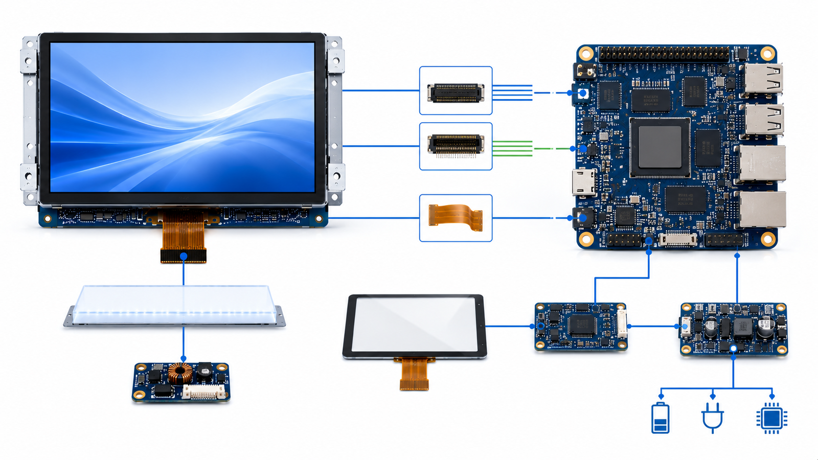
Matching a TFT LCD module with an Android control board is not only a connector problem. It is a system-level engineering decision involving display interface, resolution, timing, power sequence, backlight control, touch input, Android driver support, mechanical structure, firmware configuration, and long-term supply planning.
For OEM products, industrial HMI systems, smart control panels, medical instruments, kiosks, and embedded smart devices, a display that looks compatible on paper may still fail during integration if the control board, display module, touch panel, and Android software stack are not reviewed together. This guide explains how engineers and product teams can match a TFT LCD module with an Android control board before moving into prototype validation or mass production.
RJY supports embedded display projects that require TFT LCD modules, touch display integration, HMI systems, and Android control board matching. For projects based on Rockchip RK3566 or similar Android platforms, early technical review can reduce redesign risk and shorten the path from concept to production.
A TFT LCD module is the visual output device. An Android control board is the computing platform that runs the operating system, user interface, application software, communication services, and display output. The two must work as one system.
If the display module and Android board are not properly matched, the project may face black screen problems, wrong color mapping, unstable touch response, incorrect resolution, abnormal boot display, backlight flicker, EMI problems, power sequencing failures, or mechanical fit issues.
In a consumer product, these issues may delay launch. In an industrial or commercial device, they can also increase field service cost, complicate certification, and create long-term maintenance risk. For this reason, display selection should happen early in the hardware design process, not after the PCB and enclosure are already fixed.
Before starting the matching process, engineers should align on several common terms.
| Term | Meaning in Display Integration | Why It Matters |
|---|---|---|
| TFT LCD module | A display assembly based on thin-film transistor liquid crystal display technology. | Defines the visual output, size, resolution, interface, brightness, and mechanical constraints. |
| Android control board | An embedded computing board running Android or Android-based firmware. | Provides display output, touch processing, application software, communication, and system control. |
| Display interface | The electrical and protocol connection between the board and the display module. | Must match on both sides. Common options include MIPI DSI, LVDS, RGB, HDMI, and eDP. |
| Timing parameters | Pixel clock, horizontal sync, vertical sync, porch values, and active resolution. | Wrong timing may cause no image, shifted image, flicker, or unstable display output. |
| Touch interface | The communication path between the touch controller and Android board. | Often uses I²C or USB. Driver support is required for stable touch operation. |
| Device tree | A hardware description structure used by Linux and Android-based systems. | Helps the kernel understand connected display, touch, backlight, GPIO, and power resources. |
| Backlight control | The method used to power and dim the LCD backlight. | Usually involves LED driver circuitry and PWM or current control. |
The first question is simple: does the Android control board support the same display interface as the TFT LCD module?
Common TFT LCD display interfaces include MIPI DSI, LVDS, RGB, HDMI, and eDP. Each interface has different signal characteristics, bandwidth limits, connector requirements, PCB layout rules, software configuration needs, and use cases.
| Interface | Typical Use Case | Key Matching Point |
|---|---|---|
| MIPI DSI | Compact embedded displays, smart devices, Android HMI systems | Check lane count, resolution, command/video mode, panel initialization, and driver support. |
| LVDS | Industrial displays, medium-size TFT LCD modules, longer internal cable routing | Check channel format, bit depth, pin mapping, voltage level, and timing. |
| RGB | MCU/MPU-based embedded systems, lower to medium resolution modules | Check pixel clock, data width, sync mode, voltage, and signal integrity. |
| HDMI | Standard video output, monitors, signage, external display systems | Check whether the display module includes an HDMI receiver board or controller board. |
| eDP | Higher-resolution embedded displays, tablet-like systems, industrial panels | Check lane count, link rate, panel firmware support, and connector definition. |
MIPI DSI is defined by the MIPI Alliance as a high-speed serial interface between a host processor and a display module. It is widely used in mobile and embedded products because it can reduce pin count while supporting high-performance display output.[2]
LVDS is commonly used in industrial and embedded display systems. Texas Instruments describes LVDS display interface designs where transmitter circuitry converts parallel graphics-controller signals into serialized LVDS pairs and receiver circuitry converts them back for LCD panel use.[3]
For Rockchip RK3566-based projects, Rockchip’s official product information lists support for eDP, HDMI, MIPI, LVDS, and EBC display interfaces.[4] This makes RK3566 a practical platform for embedded Android HMI and smart display applications, but the exact board design still determines which interfaces are physically available.
After confirming the interface type, verify whether the Android board can drive the display resolution at the required refresh rate. A display may use a supported interface but still exceed the practical bandwidth, memory, or graphics capability of the board design.
Key parameters include:
For simple control panels, lower resolution may be enough and can reduce system load. For medical equipment, industrial dashboards, smart retail terminals, and multimedia interfaces, higher resolution may be required for readability and UI density.
Do not choose resolution only by visual preference. The resolution must fit the Android board, GPU capability, memory bandwidth, display interface, UI framework, enclosure size, and user viewing distance.
Display timing defines how the board sends pixel data to the LCD module. Important timing parameters include pixel clock, horizontal active area, vertical active area, front porch, back porch, sync pulse width, data enable, and polarity settings.
For MIPI DSI panels, the board may also need panel initialization commands. These commands configure the display driver IC before the Android system can show an image. If the initialization sequence is missing or incorrect, the display may stay black, show abnormal color, or fail after suspend and resume.
For LVDS and RGB panels, timing and pin mapping are especially important. The same resolution does not guarantee compatibility. Two panels may have the same pixel count but require different timing, voltage, color bit mapping, or connector definitions.
In Android-based embedded systems, these display parameters are usually configured in the board support package, kernel driver, device tree, or vendor display configuration files. Android’s device tree overlay documentation explains that a device tree overlay can apply device-specific hardware changes on top of a central device tree blob.[5]
Electrical compatibility is a common source of display integration failure. Engineers should confirm voltage levels, signal type, connector pinout, backlight requirements, power rails, reset pins, enable pins, and electrostatic protection.
At minimum, check the following:
| Item | What to Check | Risk If Ignored |
|---|---|---|
| Logic voltage | Confirm display I/O voltage matches the board. | Wrong voltage can damage the panel or board. |
| Power rails | Check panel logic power, analog power, backlight power, and touch power. | Panel may fail to start or become unstable. |
| Power sequence | Confirm order and timing for power, reset, enable, and backlight. | Can cause black screen, abnormal boot, or reduced reliability. |
| Connector pinout | Compare every pin against the panel drawing and board connector. | Pin mismatch can cause failure or hardware damage. |
| Backlight current | Check LED string voltage and current requirements. | Incorrect driver selection can cause dim display, flicker, or overheating. |
| ESD protection | Review touch, FPC, connector, and user-facing areas. | Poor protection may lead to field failures. |
The Android board may expose a display connector, but that does not mean every TFT LCD module with the same interface will be plug-and-play. Connector pitch, pin definition, FPC direction, power pins, backlight pins, reset pins, and touch pins must be verified one by one.
If the TFT LCD module includes a touch panel, the touch system must also be matched with the Android control board. Touch is usually handled separately from the display image signal.
Capacitive touch panels commonly use I²C communication, while some touch systems use USB. The Android system must include the correct touch controller driver, interrupt configuration, reset control, coordinate mapping, and calibration settings.
Touch matching should confirm:
Android display rotation does not automatically guarantee correct touch coordinate rotation. The software team should test touch mapping in portrait, landscape, and any custom UI orientation used by the final product.
The LCD panel does not emit light by itself. A TFT LCD module needs a backlight system, usually based on LEDs. The Android board or external backlight driver must provide suitable backlight power and dimming control.
Many embedded systems use PWM, or pulse width modulation, for brightness control. PWM changes perceived brightness by switching the backlight on and off at controlled duty cycles. For industrial or medical-like environments where visual comfort matters, PWM frequency, dimming range, and flicker behavior should be evaluated during sample testing.
Brightness should be selected according to the operating environment. Indoor control panels, handheld terminals, outdoor kiosks, vehicle-mounted equipment, and industrial machines may require different luminance targets and thermal designs.
For high-brightness modules, engineers should also evaluate power consumption, LED driver design, heat dissipation, enclosure ventilation, optical bonding, cover lens reflection, and backlight lifetime assumptions.
An Android control board is not only a hardware output device. The Android graphics stack must cooperate with the display hardware, GPU, kernel driver, and vendor board support package.
Android’s Hardware Composer HAL determines the most efficient way to composite buffers using available display hardware, and its implementation is usually device-specific.[6] Android documentation also explains that SurfaceFlinger uses OpenGL and Hardware Composer to compose surfaces and send output toward the display path.[7]
For an OEM project, this means display matching may require more than a cable adapter. The Android firmware may need changes to panel timing, display driver, boot logo, orientation, touch mapping, brightness control, suspend/resume behavior, and multi-display configuration.
Before freezing the design, confirm whether the Android board supplier can support:
Even if the display works electrically, it still needs to fit the product structure. Mechanical compatibility includes active area, outline dimension, thickness, mounting method, FPC position, FPC bending radius, connector placement, cover lens, bonding method, and enclosure tolerance.
Engineers should compare the TFT LCD module drawing with the product enclosure and Android board placement. The FPC should not be forced into a sharp bend, compressed against metal parts, or routed across high-noise areas without review.
For customized products, FPC direction, connector type, cover lens shape, touch sensor stack, and mounting structure may need adjustment. These changes should be discussed before the enclosure tooling stage.
Display interfaces can introduce signal integrity and electromagnetic compatibility challenges. MIPI DSI, LVDS, HDMI, and eDP all require careful PCB layout, grounding, shielding, impedance control, connector selection, and cable management.
For industrial equipment, medical instruments, transportation devices, and commercial terminals, the display subsystem should be tested under realistic conditions. Testing should include boot stability, long-duration operation, touch response, brightness adjustment, temperature exposure, ESD behavior, cable movement, and power cycling.
EMC and EMI performance depends on the complete system design. It cannot be guaranteed only by choosing a specific display module or Android board. The final enclosure, cable routing, ground design, power supply, display timing, and software behavior all matter.
Sample validation is essential before production. A display module and Android control board should be tested together with the real application UI, enclosure, power supply, touch panel, and operating environment.
A practical validation plan should include:
The earlier these issues are found, the easier they are to fix. Once the enclosure, PCB, display module, and Android firmware are all locked, any mismatch becomes more expensive to correct.
| Checklist Item | Questions to Confirm |
|---|---|
| Display size | Does the module fit the product UI and enclosure? |
| Resolution | Can the Android board drive the required resolution smoothly? |
| Interface | Do the board and module share MIPI DSI, LVDS, RGB, HDMI, or eDP compatibility? |
| Timing | Are pixel clock, sync, porch, and active area configured correctly? |
| Connector | Do pinout, pitch, FPC direction, and cable routing match? |
| Power | Are panel voltage, backlight power, touch power, and sequencing correct? |
| Touch | Is the touch controller supported by Android firmware? |
| Backlight | Does the board or driver support the required brightness and dimming method? |
| Software | Are kernel, device tree, display driver, HWC, and Android configuration ready? |
| Mechanical | Does the module fit the enclosure without FPC stress or alignment problems? |
| Lifecycle | Can the display and board remain available for the product’s expected lifecycle? |
The most common mistake is assuming that the same connector type means compatibility. A 40-pin connector, for example, can have different pin assignments, voltage levels, backlight pins, touch pins, and signal mapping.
Another mistake is treating the display as a late-stage accessory. In embedded products, the display module affects PCB layout, enclosure design, application UI, firmware, power system, thermal behavior, and certification planning. It should be reviewed at the architecture stage.
Buyers should also avoid selecting a display only by price. A low-cost module can become expensive if it requires redesign, special driver work, unstable sourcing, or mechanical changes after tooling.
RJY supports OEM teams that need to match TFT LCD modules with Android control boards for embedded display products, HMI systems, industrial terminals, smart equipment, and custom interface devices.
For Android-based HMI projects, RJY can help review display size, resolution, interface, touch type, brightness, FPC direction, connector definition, software requirements, enclosure constraints, and control board compatibility. If the project requires a Rockchip-based platform, RJY’s RK3566 Android control board can be evaluated as part of the embedded display architecture.
For special display formats, RJY also supports round and bar LCD display projects. Relevant options include the 8-inch round LCD display, 7-inch round TFT LCD display, 2.8-inch round TFT LCD display, and 11.65-inch bar LCD display.
Send your project requirements to RJY. Our engineering team can help review display size, resolution, interface, touch type, brightness, FPC direction, connector definition, Android firmware requirements, enclosure constraints, and control board compatibility.
Recommended RFQ information: display size, resolution, interface, touch type, brightness, operating environment, target application, annual volume, prototype quantity, project timeline, customization requirements, software or firmware requirements, and enclosure or mechanical requirements.
Matching a TFT LCD module with an Android control board requires a full-system review. The display interface, resolution, timing, power sequence, touch controller, backlight, Android graphics stack, mechanical structure, and lifecycle plan must all work together.
For OEM buyers, the safest approach is to select the display module and Android board as one integrated display system. Early review can reduce integration risk, simplify prototype validation, and improve the chance of a stable production design.
If your project involves an Android HMI, smart control panel, industrial display terminal, or custom embedded display device, RJY can help evaluate suitable TFT LCD modules and Android control board options based on your technical requirements.
No. The display module must match the Android control board in interface type, resolution, timing, voltage, connector pinout, backlight requirements, touch controller, and firmware support. A matching connector alone does not guarantee compatibility.
There is no single best interface for every Android HMI system. MIPI DSI is common for compact embedded displays, LVDS is widely used in industrial displays, HDMI is useful for standard video output, and eDP can be suitable for higher-resolution embedded panels. The right choice depends on resolution, board support, mechanical design, software, and lifecycle needs.
Common causes include incorrect display timing, missing panel initialization commands, wrong power sequence, mismatched pinout, unsupported interface, incorrect backlight control, missing kernel driver, or Android firmware configuration errors.
Yes. RJY can help review TFT LCD module selection, display interface, touch integration, FPC routing, backlight requirements, Android board compatibility, and HMI system requirements for RK3566-based display projects.
In many OEM projects, yes. Custom firmware or board support package changes may be needed for display timing, device tree configuration, panel driver, touch controller, screen rotation, brightness control, boot logo, and suspend/resume behavior.
Provide display size, resolution, interface, touch type, brightness, operating environment, application, annual volume, prototype quantity, project timeline, customization needs, software or firmware requirements, and enclosure or mechanical requirements.
[1] TFT LCD module, Android control board, display interface, timing parameters, device tree, and backlight control: These terms describe the core hardware and software elements involved in embedded display integration. In Android/Linux-based systems, device tree configuration helps describe hardware resources such as display panels, backlights, GPIOs, and touch controllers to the kernel. See Android Open Source Project documentation on device tree overlays: https://source.android.com/docs/core/architecture/dto
[2] MIPI DSI: MIPI DSI, or MIPI Display Serial Interface, is defined by the MIPI Alliance as a high-speed serial interface between a host processor and a display module. Source: MIPI Alliance, “MIPI Display Serial Interface”: https://www.mipi.org/specifications/dsi
[3] LVDS display interface: LVDS is used to transmit display data using differential signaling. Texas Instruments’ LDI demonstration guide explains how RGB signals from a graphics controller can be converted into serialized LVDS pairs for LCD flat panel use. Source: Texas Instruments, “LDI Demonstration Kit User Guide”: https://www.ti.com/lit/pdf/snlu036
[4] RK3566 display interfaces: Rockchip’s official RK3566 product page lists support for eDP, HDMI, MIPI, LVDS, and EBC display interfaces. Source: Rockchip RK3566 product page: https://www.rock-chips.com/a/en/products/RK35_Series/2021/0113/1274.html
[5] Device Tree Overlay / DTBO: Android documentation explains that a device tree overlay can apply device-specific hardware descriptions on top of a central device tree blob. Source: Android Open Source Project, “Device tree overlays”: https://source.android.com/docs/core/architecture/dto
[6] Hardware Composer HAL: Android’s Hardware Composer HAL determines efficient composition of buffers using available display hardware, and the implementation is device-specific. Source: Android Open Source Project, “Hardware Composer HAL”: https://source.android.com/docs/core/graphics/hwc
[7] SurfaceFlinger and Android graphics stack: Android documentation explains that SurfaceFlinger composes visible surfaces and works with Hardware Composer to send output through the display path. Source: Android Open Source Project, “Graphics architecture”: https://source.android.com/docs/core/graphics/architecture
Additional technical terms: HDMI refers to a common digital video/audio interface used for external display output. eDP refers to embedded DisplayPort, often used for embedded high-resolution panels. I²C is a two-wire serial bus frequently used by touch controllers and peripheral ICs. PWM means pulse width modulation and is commonly used for LED backlight dimming. FPC means flexible printed circuit and is used to connect compact display modules to the control board. EMI means electromagnetic interference; EMC means electromagnetic compatibility. These should be reviewed at the full-system level during embedded display design.


