A TFT LCD can show shifted rows or wrong colors even when the panel receives a stable signal. Before changing timing or swapping wires, check the memory contract between the component that writes pixels and the component that reads them. Both must agree on pixel packing, row pitch, byte order, and channel order.
This analysis covers single-plane, linear, packed RGB buffers. The formulas below do not describe tiled, compressed, or multi-plane layouts. The numerical examples are teaching cases, not hardware measurements or requirements for an RJY panel.
Describe the producer and consumer separately
The producer may be a renderer, an image decoder, or a DMA copy operation. The consumer may be a display controller scanning memory or a flush routine preparing bytes for transfer. A format name alone does not establish that these components agree.
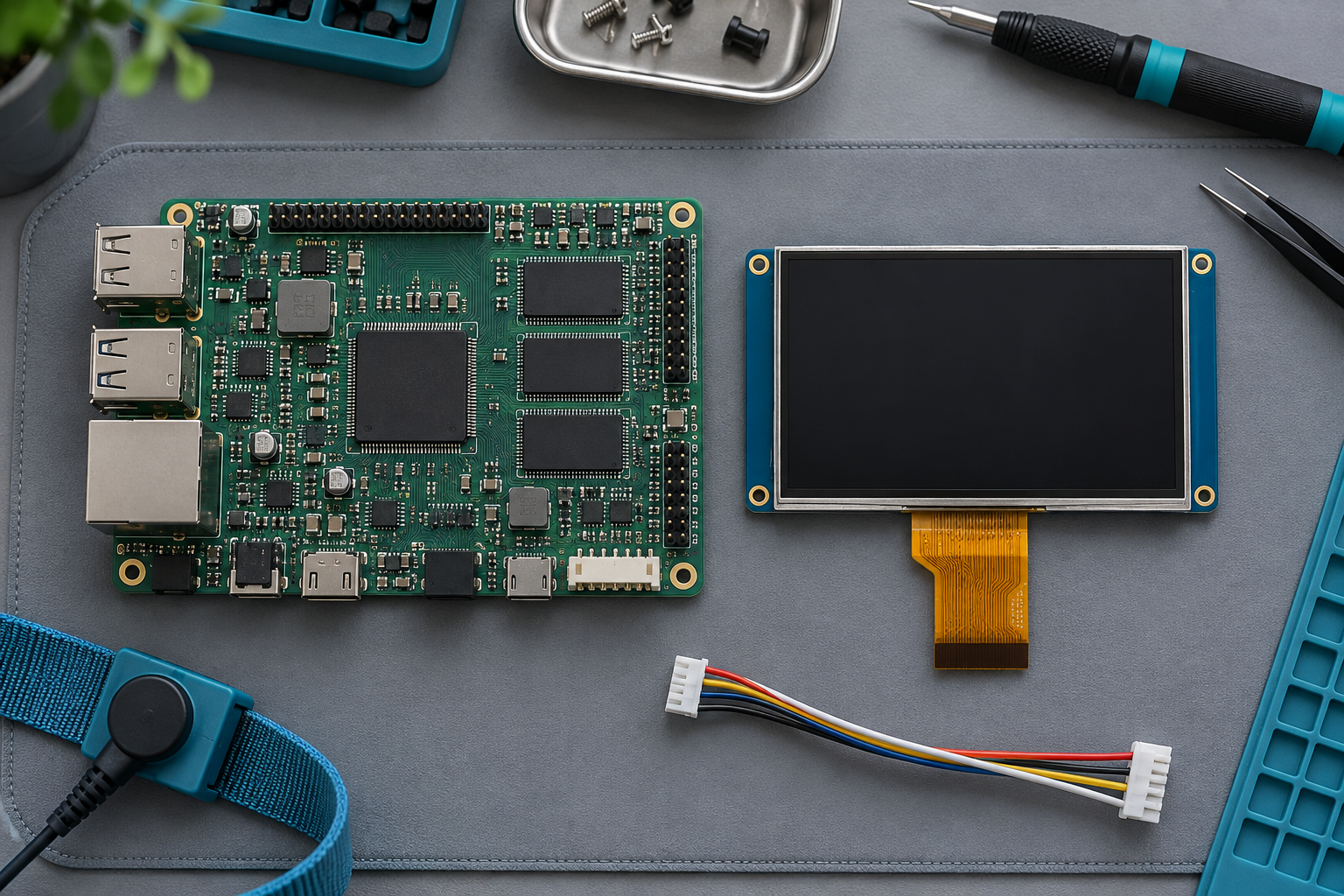
Write down what each side expects: pixel format, bytes per pixel, first-pixel offset, row pitch and its unit, image dimensions, and ownership of the buffer. If a conversion stage sits between them, it has an input contract and an output contract. Follow both rather than assuming the panel sees the renderer’s memory layout unchanged.
In Linux DRM/KMS v6.12[1], framebuffer description includes format, dimensions, pitches, offsets, and layout modifiers. The modifier matters to layout interpretation, and format support depends on the driver and display plane. Use the actual allocation and driver information; width alone does not determine pitch.
The practical consequence is to capture the buffer metadata beside the image. A screenshot without its format and pitch may show the symptom while concealing the disagreement that caused it.
Separate component precision from storage size
RGB565 allocates five bits to red, six to green, and five to blue within a 16-bit pixel value. Packed RGB888 uses three bytes per pixel. XRGB8888 uses four storage bytes. The X field does not establish an alpha channel; follow the API definition. Counting visible color components is therefore not enough to determine storage size.
| Packed format in this analysis | Storage per pixel | Common mistaken assumption |
|---|---|---|
| RGB565 | 2 bytes | Each color component occupies a whole byte |
| RGB888 | 3 bytes | A 24-bit image always uses four-byte pixels |
| XRGB8888 | 4 bytes | Three color components mean three storage bytes |
The LVGL 9.5 color-format documentation[3] lists these storage sizes and distinguishes swapping the two bytes of RGB565 from exchanging red and blue channels. Its swap-helper example is version-specific guidance, not a requirement to modify every flush buffer. Check the documentation for the version in the project.
If one stage advances three bytes per pixel while another advances four, their disagreement grows across the row. Changing a red/blue setting cannot repair that address calculation. Confirm storage size before adjusting color interpretation.
Use actual row pitch, not active width times pixel size
Active row bytes describe the pixels that belong to the image. Pitch, also called stride, describes the distance from the start of one stored row to the start of the next. Padding can make pitch larger than the active row size.
For a single-plane, linear, packed buffer with positive dimensions and a known positive byte pitch, the address of a pixel is:
pixel_address = base + offset + y * pitch_bytes + x * bytes_per_pixelHere, base identifies the allocation, offset is a nonnegative byte offset to the first image pixel, and x and y are coordinates within the image. Use nonnegative, bounds-checked coordinates and integer arithmetic that cannot overflow. Confirm that the allocation covers every address the consumer may access. For this layout, pitch must cover at least width x bytes_per_pixel active bytes per row. Check the accessed span with the actual allocation length:
offset + (height - 1) * pitch_bytes + width * bytes_per_pixel <= allocation_bytesThis bound covers the active pixels through the last row. A consumer that fetches padding or has other access requirements can need more storage. Check all additions and multiplications for overflow. These formulas do not describe other layouts.
A deliberately padded RGB565 example
Assume a 641 x 480 image with two-byte pixels. For this teaching example only, suppose the allocator rounds every row up to a multiple of 32 bytes. That assumption produces the following values:
| Quantity | Calculation | Result |
|---|---|---|
| Active row bytes | 641 x 2 | 1,282 bytes |
| Hypothetical pitch | Round 1,282 up to a multiple of 32 | 1,312 bytes |
| Padding per row | 1,312 – 1,282 | 30 bytes |
| Full-pitch allocation for all rows | 1,312 x 480 | 629,760 bytes |
| Tightly packed image size | 1,282 x 480 | 615,360 bytes |
A consumer that starts each new row after 1,282 bytes will not follow this padded layout. Conversely, a consumer expecting padding will skip useful bytes in a tightly packed image. The correct repair is to make both stages use the same layout or perform an explicit row-aware copy.
The full-pitch allocation shown here reserves the pitch for every row, including the last. It is a teaching allocation convention, not a claim about the minimum allocation every API accepts. Target allocation and access requirements remain authoritative.
Check whether the API counts bytes or pixels
ST AN4861, Revision 7[4] discusses LTDC framebuffer input formats and the distinction between active line data and pitch. Its shown HAL_LTDC_SetPitch example uses a pixel count. Do not copy a general byte-pitch value into that parameter without checking the target API and format. The note’s memory-alignment guidance belongs to its documented STM32 context.
A variable named stride is not a unit declaration. Write units into names or comments at the boundary where values cross between libraries, registers, and drivers.
Byte order and red/blue order solve different problems
The Linux v6.12 DRM format header defines RGB565 and RGB888 with little-endian storage.[2] These are API-specific definitions. Another API’s RGB name does not establish the same layout.
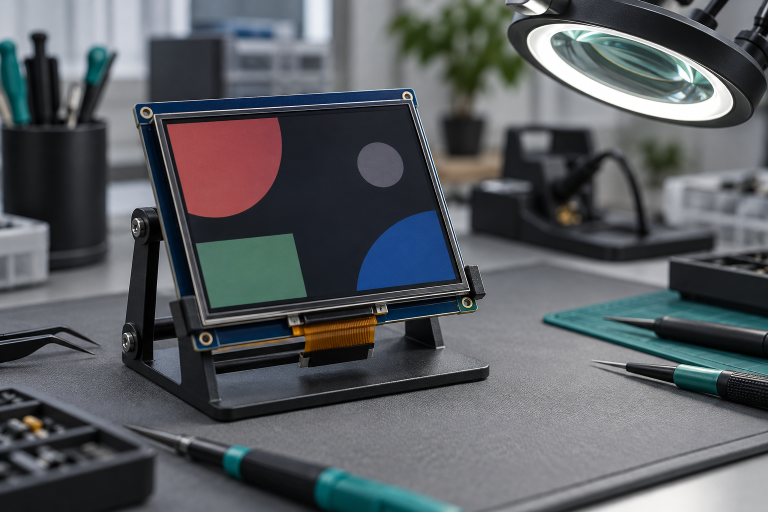
A logical RGB565 red pixel, 0xF800, occupies bytes 00 F8 in little-endian memory. A byte-serial output path might require F8 00 only if its datasheet and driver specify that sequence. The bus name alone cannot establish it.
| Operation | Result | Meaning under RGB565 |
|---|---|---|
| Original red pixel | 0xF800 | Red field at maximum |
| Swap the two bytes | 0x00F8 | Byte-swapped word, not blue |
| Swap red and blue fields | 0x001F | Blue pixel |
Use logical green 0x07E0 and blue 0x001F as additional known test values. For RGB888, specify the three bytes in increasing address order. Document any transfer-stage repacking separately.
Use a small memory fixture before changing the whole image
The following is a proposed software validation method, not a report of a tested board. Create a three-pixel-wide, two-row RGB565 fixture with an eight-byte pitch. Each row then contains six active bytes and two padding bytes. Give the padding a recognizable sentinel value.
Choose different known colors at every coordinate. Check the bytes at the start of each row and at the last active pixel. A row-aware conversion should process the six active bytes in each row and leave the padding unchanged. This exposes code that treats the allocation as one continuous array of active pixels.
For an RGB565 byte-swap operation, verify the expected output after one conversion. Applying the same swap again restores the original byte order. A second conversion can therefore hide a duplicate processing path rather than improve the result.
Also establish who owns the buffer during conversion. An in-place swap is unsuitable while another consumer still reads the old representation. A flush callback that returns before DMA completes needs a defined buffer-lifetime contract. Completion, reuse, and any required synchronization belong to the project’s actual driver model.
Choose the next check from evidence, not appearance alone
| Observed clue | Useful next check | What the clue does not prove |
|---|---|---|
| Row starts drift or diagonal displacement appears | Compare producer and consumer pitch, pixel size, and offsets | That pitch is the only possible cause |
| Red and blue appear exchanged | Compare known channel fields at each format boundary | That a two-byte swap is required |
| Known RGB565 bytes differ from the transfer contract | Inspect packing and byte order before transfer | A universal panel wire order |
| Old image regions persist after writes | Review visibility, cache maintenance, and synchronization | That a color-format change will help |
| A frame contains portions of different updates | Review update timing and buffer ownership | That memory packing is wrong |
Cache visibility, tearing, and panel timing are separate layers of investigation. Correct memory bytes do not prove that the consumer sees the latest writes, or that a frame remains unchanged while scanned. Equally, a timing change should not conceal a known pitch mismatch.
For the link-timing layer, see RJY’s LCD pixel clock and timing guide. For serialized LVDS bit placement, see the separate VESA and JEIDA mapping guide. Neither mapping nor pixel clock can be calculated from row padding alone.
Partial updates add another boundary to check. A rectangle copied from a larger framebuffer can retain the source pitch, while a temporary transfer buffer may pack only the rectangle pixels. Record the source row step and destination row step separately. The rectangle width sets the active bytes to copy; it does not automatically set either buffer pitch. Check the first and last pixel of successive rows before increasing the transfer area.
Document the contract before requesting integration support
A useful handoff identifies the exact panel and controller, host OS and GUI version, allocation layout, actual pitch with units, pixel format, and ownership rules. Include a known-pattern memory capture and the relevant datasheets. State where the first incorrect representation appears: renderer output, conversion output, transfer buffer, or displayed image.
Contact RJY Display with that evidence for project-specific TFT module or controller-board review. Any adaptation depends on the actual panel, interface, timing, backlight, touch, firmware, and application requirements. The examples here establish a debugging method, not a universal conversion or hardware fix.
References
- Linux DRM/KMS documentation, v6.12. Framebuffer metadata and layout modifiers.
- Linux DRM format definitions, v6.12. RGB565 and RGB888 storage conventions.
- LVGL color-format documentation, 9.5. Storage sizes and RGB565 byte swapping.
- ST AN4861, Revision 7. LTDC framebuffer pitch and padding; shown HAL pitch example.