Un écran TFT LCD personnalisé doit résoudre un problème d'intégration défini. Il ne doit pas commencer comme une demande ouverte visant à créer une nouvelle taille de panneau, résolution ou architecture de pixels.
Pour de nombreux projets OEM, la voie pratique consiste à identifier un module TFT LCD existant dont la zone active, la résolution, l'interface, le timing, le comportement optique et l'enveloppe mécanique sont adaptés. Le projet peut ensuite évaluer les modifications autour de cette plateforme, notamment l'écran tactile, la vitre de protection, le rétroéclairage, le FPC, le connecteur, la carte de contrôle, le firmware, la structure de collage et le boîtier.
Cette distinction affecte la faisabilité, le périmètre de développement, la documentation, l'outillage, la validation et le contrôle du cycle de vie. Elle aide également les équipes d'ingénierie à comparer des propositions qui peuvent toutes être décrites comme des “ écrans personnalisés ” mais impliquent des travaux très différents.
Qu'est-ce qu'un écran TFT LCD personnalisé ?
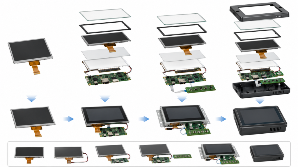
Un écran TFT LCD personnalisé est une plateforme d'affichage existante coordonnée ou modifiée pour répondre aux exigences d'un produit spécifique. Le périmètre peut aller d'un simple dessin de vitre de protection différent à un ensemble complet comprenant l'écran, le tactile, la carte de contrôle, le firmware et l'assemblage mécanique.
| Niveau du projet | Périmètre typique | Principal travail d'ingénierie |
|---|---|---|
| Module standard | Un écran TFT LCD existant est utilisé sans modification physique | Compatibilité hôte, câble, alimentation, rétroéclairage, firmware, tactile et validation mécanique |
| Module configuré | Un écran LCD existant est combiné avec une configuration disponible de tactile, vitre, câble ou contrôleur | Sélection de configuration, dessins, pilotes, assemblage et test d'échantillon complet |
| Écran semi-personnalisé | L'écran LCD principal reste inchangé tandis que les pièces environnantes sont adaptées | Vitre de protection, tactile, rétroéclairage, FPC, connecteur, collage, firmware, outillage et coordination mécanique |
| Système d'affichage intégré | Un écran LCD existant est fourni avec une carte de contrôle ou de calcul et une intégration spécifique au produit | Sortie d'affichage, pilote de panneau, entrée tactile, alimentation, rétroéclairage, logiciel, câbles et validation du boîtier |
| Demande de nouvelle plateforme de panneau | La taille, la matrice active ou la résolution requise n'est pas disponible sur une plateforme existante | Évaluation distincte de la faisabilité, du volume, de l'investissement, de la qualification, de l'approvisionnement et du cycle de vie |
La voie de personnalisation pratique de RJY Display commence par un module d'affichage existant. Elle ne doit pas être interprétée comme un développement sans restriction de n'importe quelle taille, résolution, zone active ou architecture de panneau TFT LCD.
Quand la personnalisation est-elle réellement nécessaire ?
La personnalisation n'est pas automatiquement meilleure qu'un module standard. Si un écran existant répond aux exigences électriques, optiques, mécaniques, tactiles, environnementales, logicielles et de cycle de vie obligatoires, l'utiliser sans modification peut réduire le périmètre du projet.
La personnalisation devient pertinente lorsqu'une exigence documentée ne peut pas être satisfaite par la configuration standard préférée.
| Problème observé | Réponse possible du projet | Preuve nécessaire |
|---|---|---|
| La conception avant nécessite un contour ou une bordure imprimée différent(e) | Vitre de protection personnalisée basée sur l'écran LCD et la structure tactile sélectionnés | Dessin de la vitre, matériaux, tolérances, critères d'apparence, zone de collage et CAO du boîtier |
| Le FPC de l'écran entre en conflit avec le PCB ou le boîtier | Évaluer un module alternatif, un adaptateur, un câble ou un changement de FPC réalisable | Brochage LCD, définition du connecteur, disposition du PCB, exigences de signal et enveloppe mécanique |
| L'écran fini est difficile à lire dans son environnement prévu | Revoir le rétroéclairage, l'empilement de la vitre, le traitement de surface, le collage, l'interface utilisateur et l'installation | Condition de lumière ambiante, direction de visualisation, empilement optique, budget de puissance et test d'échantillon physique |
| L'hôte n'implémente pas l'interface du panneau | Sélectionner un autre écran LCD, réviser l'hôte ou évaluer un contrôleur actif ou un pont | Révision de la carte, informations schématiques, modes de sortie supportés, timing du panneau, brochage et firmware |
| Le comportement tactile requis n'est pas supporté | Revoir le capteur, le contrôleur, le firmware, la vitre de protection, la mise à la terre et le pilote hôte | Outil d'entrée, nombre de contacts, environnement, données du contrôleur, structure de la vitre et test d'acceptation |
| Le module ne s'adapte pas à l'assemblage | Comparer une autre plateforme existante avant de commencer la personnalisation mécanique | Dessin complet de l'écran, empilement des tolérances, PCB, vitre, câble et CAO du boîtier |
Une exigence doit être classée comme obligatoire, préférée ou négociable. Cela évite qu'une préférence esthétique ne génère un travail d'outillage ou de firmware n'apportant aucun bénéfice utile au produit.
Établir la base de référence des exigences avant de sélectionner l'écran
Une revue utile d'un écran TFT LCD personnalisé commence par le produit plutôt que par une spécification d'écran générique.
| Domaine d'exigence | Questions to Resolve |
|---|---|
| Application | Que fait le produit, qui l'utilise, et quelles informations ou commandes doivent rester disponibles ? |
| Display geometry | Quelle surface active, zone d'affichage, contour, orientation, épaisseur et enveloppe du composant arrière le produit peut-il accepter ? |
| User interface | Quelle résolution, taille physique du texte, charge graphique, langues, avertissements et états système sont requis ? |
| Host platform | Quel microcontrôleur, processeur applicatif, module de calcul, carte contrôleur ou source vidéo pilotera l'affichage ? |
| Touch input | Quel doigt, gant, stylet, nombre de contacts, geste, humidité et comportement de faux toucher doivent être validés ? |
| Viewing environment | Quelles conditions de lumière ambiante, distance de visualisation, angle de montage, gradation, réflexion et température s'appliquent ? |
| Assemblage mécanique | Où se trouvent le cadre, la vitre de protection, les supports, l'adhésif, le FPC, le connecteur, le PCB, les fixations, les câbles et les sources de chaleur ? |
| Cycle de vie | Quels processus de prototype, de pré-série, de production, de contrôle des révisions, de notification des modifications et de remplacement sont requis ? |
Fournissez tôt des maquettes et dessins représentatifs de l'interface utilisateur. Une seule taille diagonale ne définit pas l'image physique, le contour du module, l'ouverture visible, la charge de pixels ou la géométrie des cibles tactiles.
Sélectionner la plateforme TFT LCD existante
Le module de base détermine quelles modifications ultérieures sont réalistes. Utilisez la fiche technique contrôlée actuelle et le dessin mécanique plutôt qu'un résumé de page produit.
Comparez les candidats en utilisant :
- Le modèle exact, la révision, le circuit intégré de pilotage et l'état actuel de l'approvisionnement
- La surface active, la zone d'affichage, le contour du module, l'épaisseur et l'orientation native
- La résolution, le format des pixels, la synchronisation native et les exigences d'initialisation
- L'interface, les niveaux électriques, les voies ou canaux, le brochage et le connecteur
- Les exigences électriques du rétroéclairage, l'activation, la gradation et le comportement thermique
- La position du FPC, la direction du contact, le renfort, les composants et la zone de pliage sécurisée
- Les caractéristiques optiques et les conditions de visualisation prévues
- Les limites de fonctionnement et de stockage documentées pour la configuration exacte
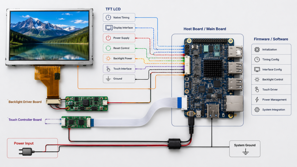
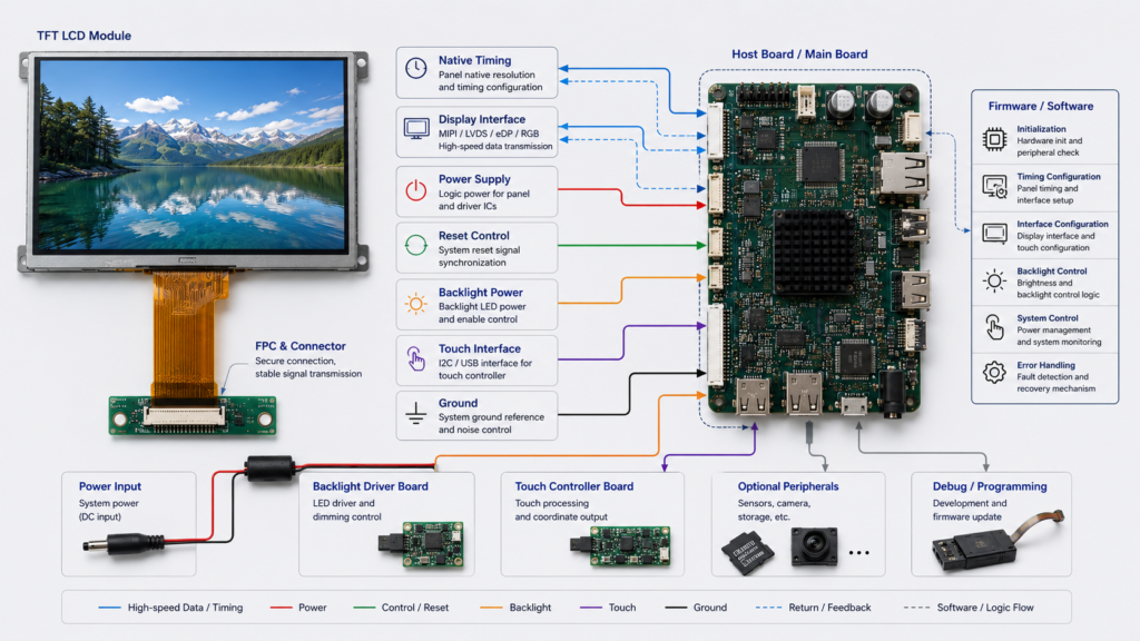
L'exemple de système d'affichage embarqué de NXP montre qu'un chemin LCD fonctionnel nécessite une synchronisation native coordonnée, une polarité du signal, une alimentation, une réinitialisation, un contrôle du rétroéclairage, des horloges d'interface et un pilote spécifique au panneau.[1] Une résolution ou une étiquette d'interface correspondante ne suffit donc pas pour approuver un module de base.
Utilisez le Guide de sélection des modules TFT LCD pour un examen plus approfondi des candidats, puis parcourez le Portefeuille actuel des modules d'affichage pour les plateformes existantes.
Personnaliser l'écran tactile et la vitre de protection ensemble
Le capteur tactile, le contrôleur tactile, la vitre de protection, la structure de liaison, l'affichage, le pilote hôte, la mise à la terre et le boîtier forment un seul système d'entrée. Un changement de la lentille avant peut modifier la conception tactile même si le LCD reste inchangé.
| Touch or Cover Area | What to Define |
|---|---|
| Technologie tactile | Configuration d'entrée capacitive projetée, résistive ou autre prise en charge |
| Contrôleur tactile | Contrôleur exact, firmware, interface hôte, tension, réinitialisation, interruption, contacts et pilote |
| Outils d'entrée | Doigt nu, gant spécifié, stylet passif, stylet actif ou entrée basée sur la pression |
| Vitre de protection | Contour, épaisseur, ouverture, bordure imprimée, matériau, détails des bords, exigences de surface et zone adhésive |
| Collage | Structure à entrefer ou liée, adhésif, alignement, apparence, tolérances et exigences de reprise |
| Software behavior | Plage de coordonnées, origine, mise à l'échelle, rotation, association d'affichage, veille, réveil et récupération |
| Environnement | Humidité, nettoyage, structures métalliques, bruit électrique, fonctionnement en bordure et critères de faux toucher |
Microchip décrit le développement de capteurs tactiles capacitifs comme un problème de conception mécanique et électrique combiné et inclut spécifiquement les effets de la vitre de protection dans le processus de conception.[2] Cela signifie qu'une vitre de protection personnalisée ne doit pas être libérée indépendamment de l'examen du contrôleur-capteur.
Sur les systèmes Android, la configuration tactile peut également contrôler l'association d'affichage, l'étalonnage et le mappage des coordonnées sensible à l'orientation.[3] Validez le firmware du contrôleur approuvé et le logiciel hôte avec la rotation finale, la vitre de protection, le cadre, la mise à la terre et le boîtier.
Pour une sélection tactile détaillée, consultez le Guide des modules TFT LCD avec écran tactile.
Personnaliser le rétroéclairage en fonction des exigences optiques et de puissance
Une demande de rétroéclairage doit commencer par l'exigence de visualisation du produit fini. La luminosité maximale disponible n'est pas automatiquement la cible correcte.
Examinez :
- Les conditions de lumière ambiante et de visualisation requises
- L'empilement LCD, polariseur, tactile, liaison, vitre de protection et traitement de surface
- La configuration des LED et les données électriques du rétroéclairage
- Le circuit de pilotage disponible, le courant, le signal d'activation et la méthode de gradation
- Le budget d'alimentation et les états de fonctionnement
- Le chauffage local et la température du boîtier fini
- Le comportement de gradation à bas niveau et le contrôle applicatif
- Les critères d'apparence et de cohérence pour l'échantillon approuvé
N'inférez pas la lisibilité en plein soleil, l'aptitude à l'extérieur, les performances thermiques ou la durée de vie opérationnelle à partir d'une valeur de luminosité nominale. Ces conclusions nécessitent des données spécifiques à la configuration et une validation du produit fini.
Coordonner l'interface, le FPC, le connecteur et la carte hôte
La personnalisation de l'interface ne consiste pas simplement à changer le nom imprimé à côté d'un connecteur. Le LCD et l'hôte doivent s'accorder électriquement, logiquement, mécaniquement et logiciellement.
| Integration Area | Éléments à confirmer |
|---|---|
| Interface d'affichage | RGB, MIPI DSI, LVDS, eDP, SPI ou une autre voie implémentée et sa configuration complète |
| Synchronisation native | Dimensions actives, horloge pixel, synchronisation, paliers, plage de rafraîchissement, format et polarité |
| Définition des broches du FPC | Chaque connexion d'affichage, de commande, d'alimentation, de masse, de réinitialisation, de rétroéclairage et tactile |
| Connecteur | Numéro de pièce, pas, côté contact, hauteur, direction d'insertion, pièce d'accouplement et accès |
| Mécanique du FPC | Direction de sortie, longueur, renfort, zone de pliage, enveloppe des composants, maintien et séquence d'assemblage |
| Chemin haute vitesse | Carte, connecteur, FPC, câble, mise à la masse, chemin de retour et revue d'intégrité du signal le cas échéant |
| Logiciels | Pilote de panneau, initialisation, régulateurs, GPIO, orientation, veille, réveil et reprise d'erreur |
La MIPI Alliance définit MIPI DSI comme une interface série haute vitesse entre un processeur hôte et un module d'affichage.[4] Un label DSI commun ne prouve pas qu'un hôte et un panneau partagent les voies requises, le mode de fonctionnement, la synchronisation, les commandes, la séquence d'alimentation, le connecteur ou le support logiciel.
Un FPC personnalisé peut réacheminer des signaux compatibles ou améliorer l'intégration mécanique. Il ne peut pas créer un contrôleur d'affichage absent, ajouter des voies non supportées, corriger des niveaux de tension incompatibles ou remplacer un firmware de panneau manquant.
Utilisez le Guide d’interface d’affichage LCD Pour le contexte inter-interface et le Guide personnalisé pour écran TFT LCD MIPI Pour l'intégration spécifique DSI.
Définir les responsabilités de la carte de contrôle et du firmware
Un contrôleur ou une carte de calcul doit être évalué au niveau de la carte. Une fiche technique de processeur peut lister des interfaces que le PCB final n'expose pas ou que l'image logicielle actuelle ne supporte pas.
Enregistrer :
- Modèle exact de la carte, configuration mémoire et révision matérielle
- Sortie d'affichage et connecteur implémentés
- Synchronisation native et configuration du panneau supportées
- Circuits d'alimentation, de réinitialisation, d'activation et de rétroéclairage du panneau
- Entrée tactile et chemin du pilote
- Version Android, Linux, RTOS, SDK MCU, noyau, BSP ou chargeur d'amorçage
- Pilote de panneau et livrables d'initialisation
- Source, binaire, configuration, construction et limites de propriété
- Comportement en mise à jour, reprise, veille, réveil et coupure d'alimentation
“ Firmware personnalisé ” n'est pas un livrable illimité. Un périmètre valide identifie la carte, l'écran LCD, le contrôleur tactile, la plateforme logicielle, la version, le comportement requis, les livrables, la propriété et les tests d'acceptation.
Pour les projets Android, suivre le guide pour Associer un module TFT LCD à une carte de contrôle Android. Les chemins de produits actuels au niveau carte sont disponibles dans Modules informatiques.
Coordonner la structure mécanique avant l'outillage
Le dessin LCD, le dessin de la couverture, le capteur tactile, le FPC, le PCB, le câble, les supports, l'adhésif, les fixations et la CAO du boîtier doivent être examinés comme une seule chaîne de tolérances.
| Élément mécanique | Exigence de revue |
|---|---|
| Zones actives et de visualisation | Alignement avec l'ouverture du cadre, l'impression de la couverture, la zone tactile et l'interface utilisateur |
| Enveloppe du module | Verre LCD, rétroéclairage, cadre, adhésif, FPC, renfort et composants arrière |
| Support et maintien | Zones approuvées de support, adhésif, support et fixation sans charge localisée sur le verre |
| Chemin du câble | Portée du FPC, pliage, accès au connecteur, maintien, chaleur, pièces mobiles et séquence d'assemblage |
| Alignement de la couverture et du tactile | Ouverture, bordure imprimée, adhésif, structure de référence et tolérances cumulées |
| Accès pour la maintenance | Fonctionnement, inspection, remplacement et protection du connecteur de l'ensemble d'affichage |
Ne pas libérer le boîtier uniquement sur la base des dimensions nominales de l'affichage. Utiliser le dessin contrôlé et inclure les conditions de matière maximale et les tolérances d'assemblage le cas échéant.
Utiliser un processus de développement d'écran personnalisé contrôlé
| Étape | Livrable requis | Question d'approbation |
|---|---|---|
| Définition des exigences | Exigences produit obligatoires, préférées et négociables | Le cahier des charges décrit-il le produit et les conditions d'acceptation ? |
| Sélection du module de base | Fiches techniques candidates, dessins, revue de compatibilité et problèmes ouverts | Une plateforme LCD existante est-elle techniquement adaptée ? |
| Revue de faisabilité | Limites de personnalisation, responsabilités, outillage, logiciel, plan de test et hypothèses commerciales | Chaque modification demandée est-elle réalisable et contrôlée ? |
| Libération du dessin et de la configuration | Définitions LCD, tactile, couverture, FPC, connecteur, carte, firmware et mécaniques | Toutes les parties examinent-elles la même révision ? |
| Construction d'échantillon | Échantillons matériels et logiciels traçables avec écarts enregistrés | L'échantillon représente-t-il la configuration de production proposée ? |
| Validation du système | Résultats des tests par rapport aux critères d'acceptation convenus | Le produit complet fonctionne-t-il dans les conditions requises ? |
| Mise en production | Configuration approuvée, critères d'inspection, emballage, contrôle des révisions et clôture des éléments ouverts | Le produit libéré est-il la même configuration que celle qui a été validée ? |
Ne commencez pas l'outillage simplement parce qu'un affichage peut montrer une image sur une carte d'évaluation. Le fonctionnement électrique n'est qu'une partie de l'approbation.
Valider l'échantillon complet d'écran TFT LCD personnalisé
| Zone de validation | Examen minimal |
|---|---|
| Identité et documentation | Modèle LCD, circuit intégré pilote, dessin, contrôleur tactile, révision de carte, micrologiciel, câbles et écarts |
| Image d'affichage | Synchronisation native, motifs plein écran, orientation, couleurs, écrans d'interface utilisateur, démarrage, veille, réveil et redémarrage |
| Touch input | Coordonnées, bords, rotation, outils de saisie requis, verre de protection, bruit, critères d'humidité, veille et réveil |
| Performance optique | Interface utilisateur requise, lumière ambiante, directions de visualisation, empilement de verre, réflexions, gradation et apparence |
| Alimentation et rétroéclairage | Démarrage, fonctionnement normal, activation, gradation, arrêt, coupure d'alimentation et température du boîtier |
| Logiciels | Chargeur d'amorçage, pilote de panneau, BSP ou SDK, application, mise à jour, récupération et états d'erreur |
| Assemblage mécanique | Alignement, support, routage FPC, accès au connecteur, adhésif, empilement de tolérances, maintien et procédure de service |
| Environnement | Conditions de température, nettoyage, humidité, mécaniques, lumière ambiante et électriques définies par l'application |
| Contrôle de configuration | Liste complète approuvée des matériaux, dessins, micrologiciel, image logicielle, enregistrement de test et problèmes non résolus |
Approuvez la configuration complète plutôt que seulement le modèle LCD. Un changement ultérieur du circuit intégré pilote du panneau, du contrôleur tactile, du verre de protection, du FPC, de la révision de carte, du micrologiciel, de l'adhésif, du rétroéclairage, du câble ou du boîtier peut nécessiter une revalidation partielle.
Préparer une demande de devis (RFQ) complète pour un écran TFT LCD personnalisé
Fournissez :
- Produit cible, utilisateurs, flux de travail et marchés de destination
- Zone active requise, résolution, orientation, contour et enveloppe mécanique
- Œuvres d'art UI à grande échelle représentatives et charge de travail graphique
- MCU exact, processeur, carte de contrôle, module de calcul ou source vidéo
- Révision de carte, sortie d'affichage implémentée, connecteur et plateforme logicielle
- Technologie tactile, contrôleur, outils de saisie, nombre de contacts et exigences environnementales
- Dessin du verre de protection, matériau, épaisseur, impression, bord, ouverture et exigences de surface
- Rétroéclairage, gradation, alimentation, lumière ambiante et exigences de visualisation
- Direction du FPC, position du connecteur, disposition PCB, câble et contraintes d'assemblage
- Micrologiciel, pilote, BSP, chargeur d'amorçage, mise à jour et portée de la récupération
- CAO du boîtier et informations sur les tolérances
- Tests requis, normes, rapports, déclarations et parties responsables
- Prototype, pilote, production et quantités annuelles prévues
- Cycle de vie, révision, notification de changement et attentes de remplacement
- Documentation d'affichage existante lors du remplacement d'un autre module
Pour une préparation spécifique aux coûts, consultez le guide de tarification des écrans LCD TFT personnalisés.
Demander une revue technique d'un écran TFT LCD personnalisé
RJY Display peut examiner une plateforme LCD TFT existante par rapport à vos exigences tactiles, de verre de protection, de rétroéclairage, de FPC, d'interface, de carte de contrôle, de micrologiciel, d'alimentation, optiques et mécaniques.
Parcourir les modules d'affichage actuels, examinez Portée de la solution personnalisée de RJY Displayou envoyez votre affichage, carte, UI et documents de boîtier pour une révision technique.
FAQ
Qu'est-ce qu'un écran LCD TFT personnalisé ?
Un écran LCD TFT personnalisé est normalement une plateforme d'affichage existante configurée ou modifiée pour un produit spécifique dans des domaines tels que le tactile, le verre de protection, le rétroéclairage, le FPC, l'interface, la carte de contrôle, le micrologiciel, le collage ou la structure mécanique.
RJY Display peut-il développer une nouvelle taille ou résolution d'écran LCD ?
Non. La voie de personnalisation pratique commence par un module d'affichage existant. Une demande pour une taille, une matrice active, une résolution ou une nouvelle architecture de panneau indisponible nécessite une étude de faisabilité séparée et ne doit pas être considérée comme disponible.
Quelles parties d'un module LCD TFT peuvent être personnalisées ?
Selon le module de base sélectionné et la faisabilité du projet, le travail peut inclure le verre de protection, l'écran tactile, le collage, le rétroéclairage, le FPC, le connecteur, la coordination d'interface, la carte de contrôle, le micrologiciel et la structure mécanique.
Le changement du FPC rend-il un écran LCD compatible avec ma carte ?
Non. Un FPC peut acheminer des signaux compatibles et améliorer l'ajustement mécanique, mais il ne peut pas ajouter un contrôleur d'affichage manquant, créer des voies non supportées, corriger une tension ou un timing incompatible, ni remplacer un micrologiciel de panneau absent.
Que faut-il tester sur un échantillon d'affichage personnalisé ?
Testez le timing et l'image d'affichage documentés, le comportement tactile, l'empilement de verre, la performance optique, l'alimentation et le rétroéclairage, le micrologiciel, le démarrage et la récupération, la charge de travail de l'application, l'assemblage mécanique, les conditions environnementales requises et l'identité complète de la configuration.
Quelles informations sont nécessaires pour un devis d'écran LCD TFT personnalisé ?
Fournissez l'application, la géométrie d'affichage, la résolution, les œuvres d'art UI, la carte hôte, l'interface, les exigences tactiles et de verre de protection, les besoins en rétroéclairage et alimentation, les contraintes FPC et connecteur, la portée du micrologiciel, les dessins du boîtier, les exigences de validation, les quantités et les attentes de cycle de vie.
Références
- NXP Semiconductors, “ AN12940 : Cas d'utilisation du système d'affichage LCD RT1170 basé sur MIPI DSI. ” https://www.nxp.com/docs/en/application-note/AN12940.pdf
- Microchip Technology, “ AN2934 : Conception de capteur tactile capacitif ”, 24 juillet 2020. https://www.microchip.com/en-us/application-notes/an2934
- Android Open Source Project, “ Périphériques tactiles. ” https://source.android.com/docs/core/interaction/input/touch-devices
- MIPI Alliance, “ Interface série d'affichage MIPI (MIPI DSI). ” https://www.mipi.org/specifications/dsi