
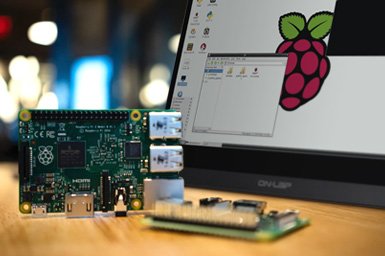
For embedded software engineers, hardware hackers, and industrial IoT architects, the Raspberry Pi is the undisputed king of rapid prototyping. In its default “headless” state (accessed via SSH), it is a silent, invisible workhorse. But the moment you need a Human-Machine Interface (HMI)—whether you are building a smart home thermostat, a factory floor control panel, or a bespoke medical device prototype—you must bridge the gap between code and physical interaction.
Integrating a tft lcd raspberry pi display is often the most frustrating rite of passage in hardware development. If you have ever plugged a screen into your Pi’s GPIO headers only to be greeted by the infamous “White Screen of Death,” you know exactly how complex this integration can be.
This comprehensive, step-by-step engineering guide will walk you through the precise hardware connections, the underlying Linux Device Tree overlays, and the modern Wayland/X11 software configurations required to successfully deploy a TFT LCD on a Raspberry Pi.
1. Architectural Triage: Understanding Your Display Interface
Before you touch a single jumper wire or type sudo nano, you must understand how your display communicates with the Raspberry Pi. The method of connection entirely dictates the frame rate, the CPU overhead, and the software drivers required.
There are four primary ways to connect a tft lcd raspberry pi display.
A. The SPI Interface (Serial Peripheral Interface)
This is the most common interface for small displays (1.5″ to 3.5″). These displays sit directly on the 40-pin GPIO header.
- The Reality: SPI is a serial protocol. It sends pixel data one bit at a time. It is inherently slow.
- Use Case: Perfect for static user interfaces, sensor readouts, or text-heavy dashboards.
- Limitations: Do not expect to play 60 FPS video on an SPI screen. You are physically limited by the SPI bus speed (typically capped around 32MHz to 48MHz), which yields a maximum of 15 to 25 FPS on a 320×480 resolution screen. High CPU overhead is required to push the pixels.
B. The MIPI DSI Interface (Display Serial Interface)
This utilizes the dedicated ribbon cable connector on the Raspberry Pi board (labeled “DISPLAY” or “MIPI” on Pi 5 models).
- The Reality: DSI is a high-speed, differential signaling interface that taps directly into the Raspberry Pi’s Broadcom GPU.
- Use Case: The absolute best option for fluid UIs, video playback, and complex graphics. It frees up the CPU entirely and leaves your GPIO pins available for other sensors.
- Limitations: DSI displays are typically limited to official Raspberry Pi screens or specific third-party models with custom bridge chips.
C. The DPI Interface (Display Parallel Interface)
DPI uses almost all the GPIO pins (up to 24 pins for RGB888 color, plus sync signals) to drive a raw LCD panel.
- The Reality: It offers HDMI-like speeds and zero CPU overhead without using the bulky HDMI port.
- Use Case: Custom arcade cabinets or industrial builds where the HDMI port is blocked or needed for a secondary screen.
- Limitations: You lose almost all of your GPIO pins. You cannot easily add I2C sensors or SPI buttons.
D. The HDMI / USB Combo
Large tft lcd raspberry pi screens (5-inch to 10-inch) often use standard HDMI for the display signal and a USB cable for the touch interface.
- The Reality: Plug-and-play simplicity. The Pi treats it like a standard desktop monitor.
- Limitations: Bulky cabling. It is difficult to integrate cleanly into a slim, bespoke product enclosure.
For the purpose of this hands-on guide, we will focus on the most notoriously difficult integration: the SPI-based GPIO display, as it requires the deepest understanding of the Linux kernel.
2. Hardware Assembly: Wiring the SPI Display
If your SPI display does not snap directly onto the GPIO headers as a “HAT” (Hardware Attached on Top), you will need to wire it manually.
The Golden Rule of Hardware
Never wire a display while the Raspberry Pi is powered on. Hot-plugging GPIO pins can cause a voltage spike that will instantly destroy the LCD driver IC or, worse, fry the Raspberry Pi’s Broadcom SoC.
The SPI Pinout Anatomy
To make a standard SPI tft lcd raspberry pi screen work, you must connect the power, the SPI bus (MOSI, SCLK, CE), and the control pins (DC, Reset).
Here is the standard mapping you must execute using female-to-female jumper wires:
| Display Pin | Function | Raspberry Pi Physical Pin | Raspberry Pi BCM GPIO |
| VCC/5V | Power | Pin 2 or 4 | 5V Power |
| GND | Ground | Pin 6 (or any GND) | Ground |
| MOSI (SDI) | Data to Screen | Pin 19 | GPIO 10 (SPI0_MOSI) |
| SCLK (SCK) | SPI Clock | Pin 23 | GPIO 11 (SPI0_SCLK) |
| CS / CE0 | Chip Select | Pin 24 | GPIO 8 (SPI0_CE0) |
| DC / RS | Data/Command | Pin 22 (Common default) | GPIO 25 |
| RST / RES | Reset | Pin 18 (Common default) | GPIO 24 |
| BLK / LED | Backlight | Pin 12 (PWM) or 3.3V | GPIO 18 (PWM0) |
Engineering Tip: The DC (Data/Command) pin is crucial. SPI only sends 1s and 0s. The display controller (like the ILI9341) needs to know if those 1s and 0s are pixel color data or system commands (like “turn on screen”). The DC pin toggles high or low to tell the controller how to interpret the incoming SPI data.
3. Kernel Configuration: The Device Tree Overlay
You have wired the screen. You turn on the Pi. The screen lights up, but it is purely white. This is the White Screen of Death. It means the backlight has power, but the Raspberry Pi kernel has no idea the screen exists, so it is not sending any pixel data.
We must tell the Linux kernel how to talk to the screen. In modern Raspberry Pi OS (Bookworm and later), this is done via Device Tree Overlays (dtoverlay).
Step 3.1: Enable the SPI Bus
First, you must unlock the SPI hardware on the Pi.
- SSH into your Raspberry Pi.
- Run the configuration tool:Bash
sudo raspi-config - Navigate to Interface Options -> SPI -> Select Yes to enable.
- Reboot the Pi.
Step 3.2: Identify Your Display Controller (The Driver)
TFT LCD panels are dumb glass. They are driven by a microchip glued to the back of the glass (or on the PCB). The most common controllers in the European/US maker markets are:
- ILI9341 (Very common for 2.4″ to 2.8″ screens)
- ST7789 (Common for 1.3″ to 2.0″ IPS screens)
- ILI9486 (Common for 3.5″ screens)
You must know which controller your screen uses. Check the manufacturer’s datasheet.
Step 3.3: Edit config.txt
In modern Raspberry Pi OS, the boot configuration file has moved.
Open it using the nano text editor:
Bash
sudo nano /boot/firmware/config.txt
(Note: On older Bullseye OS versions, the path is just /boot/config.txt)
Scroll to the bottom of the file and add the specific overlay for your driver. For example, if you are using an ILI9341 screen wired exactly as the table above:
Ini, TOML
# Enable SPI
dtparam=spi=on

# Load the ILI9341 driver overlay
dtoverlay=rpi-display

# If you wired the DC and RESET pins differently, you must declare them:
# dtoverlay=rpi-display,dc_pin=25,reset_pin=24,speed=32000000
For an ST7789 display (commonly used in Adafruit PiTFTs):
Ini, TOML
dtoverlay=adafruit-st7789v-hAT,fps=30
Save the file (Ctrl+O, Enter) and exit (Ctrl+X).
Reboot the Raspberry Pi: sudo reboot.
If configured correctly, the white screen will turn black during boot, and you will eventually see the Linux console text scrolling down the tiny screen.
4. Modern Graphics Architectures: FBCP vs. DRM/KMS
Here is where many tutorials from 2020 will lead you astray.
Historically, if you wanted to mirror your main HDMI desktop to a tiny SPI tft lcd raspberry pi display, you used a tool called fbcp (Framebuffer Copy). It took a snapshot of the primary GPU framebuffer (fb0) and aggressively copied it to the SPI screen’s framebuffer (fb1).
The Wayland Reality Check
Starting with Raspberry Pi OS Bookworm, the X11 windowing system and the legacy framebuffer architecture were abandoned. The Pi now uses Wayland (specifically the Wayfire compositor) and the DRM/KMS (Direct Rendering Manager / Kernel Mode Setting) architecture.
fbcp no longer works on modern Raspberry Pi OS.
How to drive the UI today:
If you are building an industrial HMI or a custom device, you should not be trying to run a full desktop GUI on a 3.5-inch screen anyway. Instead, you should write an application that renders directly to the DRM/KMS layer using hardware-accelerated libraries.
The Professional Stack:
- LVGL (Light and Versatile Graphics Library): An open-source C library that writes directly to the Linux DRM subsystem. It is incredibly lightweight and perfect for SPI screens.
- Qt / PyQt: You can configure Qt applications to run using the
eglfsorlinuxfbplugins, bypassing the Wayland desktop entirely and drawing your UI directly to the TFT LCD. - Kiosk Mode: If you absolutely must use web technologies (HTML/CSS/JS), you can configure Wayfire to boot directly into a fullscreen Chromium browser pointing to a local Node.js server.
5. Calibrating the Touch Interface
If your tft lcd raspberry pi has a touch overlay, getting the screen to display an image is only half the battle. Now you must ensure that when you tap the top-left corner, the mouse cursor actually goes to the top-left corner.
Resistive vs. Capacitive Touch
- Resistive (XPT2046 Controller): Requires pressure. Very common on cheap 3.5″ SPI screens. Requires intense calibration because the analog resistance varies by temperature and manufacturing batch.
- Capacitive (FT6236 / Goodix Controllers): Like a smartphone. Generally requires zero calibration as the grid is digitally mapped to the pixels at the factory. Uses the I2C bus instead of SPI.
Calibrating an XPT2046 Resistive Screen under Wayland/Libinput
Because X11 is dead, the old xinput_calibrator tool is obsolete. Today, touchscreens are handled by libinput and udev rules.
- First, ensure the touch driver is loaded in
/boot/firmware/config.txt:Ini, TOMLdtoverlay=ads7846,cs=1,penirq=17,penirq_pull=2,speed=1000000,keep_vref_on=1 - Reboot and install the libinput calibration tool:Bash
sudo apt install weston - Wayfire (the default compositor) uses a specific configuration file for input devices. You must edit the Wayfire config to map the touch matrix correctly.Open
~/.config/wayfire.iniand locate the[input]section. You will need to add a calibration matrix.(Note: The exact matrix depends on whether your screen is landscape or portrait. A default identity matrix is1 0 0 0 1 0.)
If your touch axes are inverted (moving your finger up moves the mouse down), you must flip the matrix values. For example, to invert the Y-axis, your udev rule or Wayfire config matrix would change the Y-scale multiplier to a negative value.
6. Overclocking the SPI Bus (Chasing Frames)
If your user interface feels sluggish, you can attempt to overclock the SPI bus to squeeze a few more frames per second out of the tft lcd raspberry pi.
Open /boot/firmware/config.txt and locate your driver overlay line. Add the speed parameter (measured in Hz).
Ini, TOML
dtoverlay=rpi-display,speed=48000000
This requests a 48 MHz SPI clock.
Warning: The Raspberry Pi’s SPI core clock operates on a divider system. If you request 48MHz, you will likely get it. If you request 60MHz, the Pi might divide its core clock and drop you down to 31MHz instead, making it slower. Furthermore, if you push the speed too high (e.g., 80000000), the physical jumper wires will act as antennas, introducing electromagnetic interference (EMI) that corrupts the data, resulting in a screen filled with static “snow” or inverted colors. Keep your wires as short as physically possible (under 10cm) if you intend to push the SPI speed.
Conclusion: The Engineering Payoff
Setting up a tft lcd raspberry pi is rarely a plug-and-play experience. It demands a working knowledge of serial protocols, Linux kernel overlays, and display rendering architectures. However, mastering this process is a critical skill for any hardware developer.
By bypassing bulky HDMI monitors and natively driving an SPI or DSI display, you unlock the ability to design highly integrated, professional-grade hardware prototypes. Whether you are building an industrial telemetry dashboard or a bespoke digital audio player, that glowing piece of glass transforms your invisible code into a tangible, interactive product.
Frequently Asked Questions (FAQ)
Q1: Why is my SPI display completely white when I boot the Pi?
A: This is the most common issue. A white screen means the backlight has 3.3V or 5V power, but the display controller IC is not receiving data.
- Check wiring: Verify MOSI, SCLK, and specifically the CS (Chip Select) and DC (Data/Command) pins.
- Check config: Ensure
dtparam=spi=onis active in your/boot/firmware/config.txt. - Check driver: Ensure you are loading the correct
dtoverlayfor your specific screen’s controller chip (e.g., ILI9341 vs. ST7789).
Q2: Can I run a standard desktop GUI (like Chromium or VLC) on a 3.5-inch SPI screen?
A: Technically yes, but practically no. The SPI bus simply does not have the bandwidth to push 320×480 pixels at 60 frames per second. Video playback will result in aggressive screen tearing, and the desktop UI will feel incredibly sluggish. For desktop environments or video, you must use a MIPI DSI or HDMI display. SPI screens are for simple, static GUIs, buttons, and text readouts.
Q3: My touchscreen clicks register, but the mouse cursor goes to the opposite side of the screen. How do I fix this?
A: Your touch axes are inverted relative to your display axes. This happens if you rotate the display in software (e.g., display_lcd_rotate=2) but do not rotate the touch matrix. You must apply a Transformation Matrix via udev rules or inside your Wayfire/X11 configuration to swap the X and Y axes or invert them.
Q4: Will adding an LCD screen overload my Raspberry Pi’s power supply?
A: It can, depending on the Pi model and the screen size. A Raspberry Pi 4 or 5 requires a robust 5.1V / 3A to 5A power supply. A 3.5-inch SPI screen draws around 100mA to 150mA for its LED backlight, which the 5V GPIO pins can handle safely. However, a 7-inch or 10-inch screen can draw upwards of 500mA to 1A. For screens larger than 5 inches, you should power the screen from an external dedicated USB power supply, not from the Pi’s GPIO pins, to prevent under-voltage throttling (indicated by the yellow lightning bolt icon).
Q5: I want to build a commercial product using a Raspberry Pi Compute Module. Should I use SPI?
A: No. If you are moving to a commercial product using a Compute Module 4 (CM4) or CM5, you should route the MIPI DSI lines or utilize the DPI (Parallel) interface on your custom carrier board. This offloads the display rendering to the hardware GPU, freeing up the CPU to run your actual application logic and ensuring smooth, professional-grade 60 FPS animations.


