임베디드 디스플레이 프로젝트에 병목 현상을 겪고 계신가요?
복잡한 통합 작업이나 공급망 문제로 출시 시기가 지연되지 않도록 하십시오. 맞춤형 설계 및 제조 지원을 위해 RJY 전문가 팀과의 무료 상담을 예약하세요.

배터리 에너지 저장 시스템은 배터리 랙, 배터리 관리 전자장치, 전력 변환 시스템, 사이트 제어장치, 에너지 관리 시스템, 보조 장비, 원격 감시 소프트웨어 및 로컬 운전자 인터페이스를 결합할 수 있습니다. TFT LCD는 해당 인터페이스에 중요하지만, 배터리 관리 시스템, 전력 변환기, 파견 제어기, 화재 방호 시스템 또는 BESS의 안전성이나 계통 적합성을 입증하는 장치는 아닙니다.
디스플레이 선정은 로컬 운전 및 서비스 워크플로우에서 시작해야 합니다. 장비 팀은 인클로저에서 어떤 정보를 계속 사용할 수 있어야 하는지, 어떤 작업이 로컬에서 요청될 수 있는지, 어떤 기능이 권한이 있는 원격 시스템에만 속하는지, 그리고 데이터 또는 통신을 사용할 수 없을 때 인터페이스가 어떻게 동작하는지 결정해야 합니다.
본 가이드는 BESS 로컬 HMI용 TFT LCD를 선정하고 통합하는 방법을 설명하면서, 디스플레이, 터치 입력, HMI 호스트, BMS, PCS, EMS, SCADA 및 독립적인 안전 기능을 명확하게 분리하여 유지하는 방법을 안내합니다.
유용한 BESS 아키텍처 다이어그램은 모든 주요 기능 계층을 식별해야 합니다. 배터리 관리 시스템은 시스템 설계 내에서 배터리 관련 정보와 한계값을 모니터링하고 관리합니다. 전력 변환 시스템은 저장 장치와 연결된 AC 계통 사이의 전력 전자 경로를 제공합니다. 로컬 또는 중앙 에너지 관리 시스템은 운전 목표와 명령을 조정할 수 있습니다. SCADA 또는 다른 감시 플랫폼은 사이트 수준 또는 원격 모니터링 및 제어를 제공할 수 있습니다.
미국 에너지부(DOE)는 배터리 관리, 전력 변환, 계통 인터페이스, 제어 하드웨어 및 소프트웨어를 통합하는 BESS 아키텍처를 설명합니다.1 샌디아 국립연구소(Sandia National Laboratories)는 또한 배터리 및 PCS 운전 정보가 EMS로 이동하고 명령이 정의된 제어 아키텍처를 통해 전달되는 계층 구조를 제시합니다.2
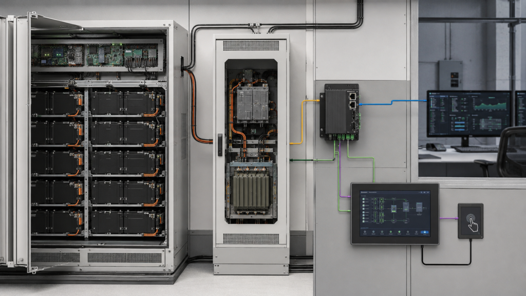
로컬 TFT HMI는 해당 아키텍처에서 선택된 정보를 표시합니다. 내장 호스트는 장비 개요, 통신 상태, 허용된 서비스 기능, 알람 이력 또는 유지보수 내비게이션을 렌더링할 수 있습니다. 디스플레이 자체는 셀 전압을 측정하거나, 충전 상태를 추정하거나, 충전 또는 방전 한계를 결정하거나, 전력 반도체에 명령을 내리거나, 사이트 최적화를 수행하지 않습니다.
터치 입력 또한 제어 결정이 아닙니다. 터치 컨트롤러는 좌표 또는 제스처를 HMI 호스트에 보고합니다. 완성된 애플리케이션이 요청된 작업이 현재 운전 상태에서 표시 가능한지, 권한이 있는지, 유효한지, 그리고 적절한 컨트롤러에 의해 수락되는지 결정합니다.
많은 BESS 설치에는 원격 모니터링이 포함되지만, 이것이 로컬 인터페이스의 필요성을 자동으로 제거하지는 않습니다. 시운전 인력은 캐비닛 근처에서 장비 개요가 필요할 수 있습니다. 서비스 기술자는 영향을 받은 하위 시스템을 식별하고, 통신 가용성을 검토하고, 장비 식별 정보를 확인하거나, 인클로저와 원격 워크스테이션 사이를 반복적으로 이동하지 않고 정의된 유지보수 워크플로우를 수행해야 할 수 있습니다.
로컬 HMI는 모든 SCADA 화면을 단순히 복제해서는 안 됩니다. 컴팩트한 내장 디스플레이는 공간, 그래픽, 보안, 환경 및 서비스 측면에서 다른 제약 조건을 가집니다. 프로젝트 팀은 장비에서 어떤 정보가 필수적인지, 그리고 어떤 상세 분석이 더 큰 엔지니어링 워크스테이션에 속하는지 정의해야 합니다.
대표적인 워크플로우에는 초기 시동 관찰, 권한이 부여된 모드 검토, 하위 시스템 가용성, 활성 및 이력 알람, 통신 진단, 유지보수 접근, 소프트웨어 및 하드웨어 식별, 통제된 복구가 포함될 수 있습니다. 정확한 기능은 BESS 아키텍처에 따라 달라지며 장비 설계자의 승인을 받아야 합니다.
로컬 디스플레이를 대체 보호 경로로 취급하지 마십시오. 배터리 한계값, 전력 전자 보호, 차단 기능, 비상 제어, 화재 감지 및 기타 안전 관련 기능은 독립적으로 설계된 시스템 계층에 유지되어야 합니다.
BESS는 대량의 데이터를 생성할 수 있지만, 로컬 화면은 정의된 현장 의사결정에 필요한 정보를 우선시해야 합니다. 기본 화면은 장비 가용성, 운전 모드, 통신 상태, 유지보수 상태 및 알람 우선순위를 구분할 수 있어야 합니다. 더 깊은 화면은 문제 해결을 지원할 때 권한이 있는 사용자에게 하위 시스템 세부 정보를 노출할 수 있습니다.
충전 상태, 온도, 전압, 전류, 전력 및 기타 값은 서로 다른 장치, 모델 또는 집계 수준에서 발생할 수 있습니다. HMI는 시스템 소프트웨어가 제공하는 컨텍스트를 명확하게 식별해야 합니다. 매력적인 숫자 표시는 소스, 타임스탬프, 정확도, 계산 방법 또는 단위 변환을 검증하지 않습니다.
GUI 프로토타이핑 중에는 현실적인 데이터 구조를 사용하십시오. 긴 장치 이름, 여러 랙 또는 전력 변환 장치, 사용 불가 값, 지연된 데이터, 상충되는 하위 시스템 상태, 번역, 알람 텍스트, 타임스탬프, 사용자 권한, 확인 대화상자 및 유지보수 화면을 포함하십시오. 플레이스홀더 대시보드는 양산 콘텐츠에 필요한 공간을 과소평가하는 경우가 많습니다.
색상만으로 중요한 상태를 전달해서는 안 됩니다. 색상을 형태, 위치, 문구 또는 다른 시스템 정의 신호와 결합하십시오. 의도된 시청 조건에서 완성된 GUI를 검증하고, 패널의 특정 색상이 알람 조건이 올바르게 감지되었음을 증명한다고 가정하지 마십시오.
올바른 패널 크기는 시청 거리, 장착 높이, 서비스 위치, 정보 밀도, 터치 대상 크기, 인클로저 공간 및 동시 장비 컨텍스트의 양에 따라 달라집니다. 로컬 상태 및 유지보수에만 사용되는 화면은 제어실 모니터와 동일한 크기가 필요하지 않을 수 있습니다.
의도된 물리적 크기에서 대표 화면을 검토하십시오. 전체 내비게이션, 가장 긴 예상 알람 항목, 장비 계층 구조, 확인 단계, 필요한 경우 트렌드 창 및 가상 키보드를 포함하십시오. 사용자가 과도한 내비게이션 없이 현재 자산, 하위 시스템, 모드 및 데이터 경과 시간을 구분할 수 있는지 확인하십시오.
해상도는 HMI 호스트에 불필요한 부하를 만들지 않으면서 읽기 쉬운 타이포그래피와 필요한 그래픽을 지원해야 합니다. 더 높은 픽셀 수는 프레임버퍼, 메모리 대역폭, 렌더링, 부팅 및 때로는 열 요구 사항을 증가시킵니다. 패널 해상도, GUI 프레임워크, 운영 체제, 프로세서, 메모리 및 업데이트 동작을 함께 평가해야 합니다.
상세한 다중 사이트 트렌드 또는 엔지니어링 분석은 원격 워크스테이션에서 처리하는 것이 더 나을 수 있습니다. 내장 TFT는 전체 SCADA 환경을 재현할 것으로 기대하기보다 정의된 로컬 역할을 위해 선택되어야 합니다.
로컬 BESS 패널은 옥외, 캐비닛 도어 내부, 커버 창 뒤 또는 보호된 서비스 구획 내에 장착될 수 있습니다. 각 위치는 서로 다른 광학 요구 사항을 만듭니다. 직사광선 및 반사광, 밝은 흐린 조건, 낮은 각도의 눈부심, 그늘, 야간 서비스 조명, 시야각 및 작업자 복장이나 주변 장비의 반사를 평가하십시오.
밝기만으로 가독성이 결정되지 않습니다. 커버 렌즈, 터치 센서, 에어갭 또는 본딩, 표면 처리, 대비 동작, 편광판, 인클로저 차양, GUI 색상 및 시야 방향이 모두 완성된 결과에 영향을 미칩니다. 베어 패널 데이터시트에만 의존하지 말고 양산 의도 광학 스택을 테스트하십시오.
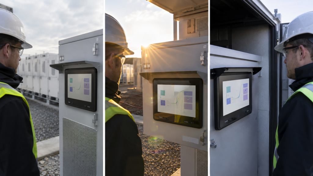
주간 및 야간 동작은 HMI 호스트 및 백라이트 회로와 함께 조정되어야 합니다. 사용 가능한 디밍 범위, 시작 밝기, 깨어남 전환, 저조도 안정성, GUI 테마 및 통신 또는 애플리케이션 재시작 후 복구를 검토하십시오. 야간의 과도한 밝기는 주간의 불충분한 출력만큼 부적합할 수 있습니다.
선택된 어셈블리가 정의된 조명, 콘텐츠, 각도, 커버 및 수용 기준에 대해 평가되지 않은 한 “햇빛 가독성”을 주장하지 마십시오. "옥외용 디스플레이"는 프로젝트 범주일 뿐, 모든 BESS 인클로저에서의 성능을 입증하는 것은 아닙니다.
로우 TFT LCD는 RGB, LVDS, MIPI DSI, eDP 또는 다른 네이티브 인터페이스를 사용할 수 있습니다. 호환성을 위해서는 호스트와 패널이 전기적 레벨, 픽셀 형식, 해상도, 타이밍, 레인 또는 버스 구성, 커넥터 핀아웃, 초기화, 전원 시퀀스, 백라이트 제어 및 소프트웨어 지원에 대해 일치해야 합니다.
프로세서 인터페이스 문서는 실제 플랫폼에 대해 구성 검증이 필요한 이유를 보여줍니다. 예를 들어, NXP의 LCDIF 문서는 지원되는 디스플레이 인터페이스에 대한 구성 구조와 드라이버 동작을 정의하지만, 임의의 프로세서, 케이블 및 TFT 패널이 자동으로 함께 작동한다고 명시하지는 않습니다.3
선택된 컴퓨터가 HDMI를 제공하는 반면 로우 TFT가 MIPI DSI, RGB, LVDS 또는 eDP를 요구하는 경우, 수동 케이블로는 신호를 변환할 수 없습니다. 설계에는 소스 및 정확한 패널과 호환되는 능동 컨트롤러 또는 브리지가 필요합니다. 해당 장치는 펌웨어, 시동, 전원, 열, EMC, 케이블 및 수명 주기 계획의 일부가 됩니다.
완성된 외부 HDMI 모니터와 로우 임베디드 TFT 모듈은 다른 제품입니다. 외부 모니터에는 자체 수신 및 디스플레이 제어 전자장치가 포함되어 있습니다. 로우 패널은 호환되는 네이티브 디스플레이 경로 또는 의도적으로 선택된 능동 컨트롤러에 의존합니다.
프로젝티드 커패시티브 또는 저항막 터치 시스템에는 자체 센서, 컨트롤러, 연결, 펌웨어, 접지 요구 사항 및 소프트웨어 입력 경로가 있습니다. 이는 LCD 픽셀 데이터를 전달하지 않으며 시스템 권한을 독립적으로 강제하지 않습니다.
터치 요구 사항은 장갑 사용, 습기, 먼지, 표면 오염, 커버 두께, 대상 크기, 접지, 인클로저 구조 및 주변 전기 노이즈를 정의해야 합니다. 모든 커패시티브 터치 시스템이 모든 장갑 또는 습윤 조건을 지원하는 것은 아닙니다. 양산 커버 스택과 인클로저를 함께 테스트해야 합니다.
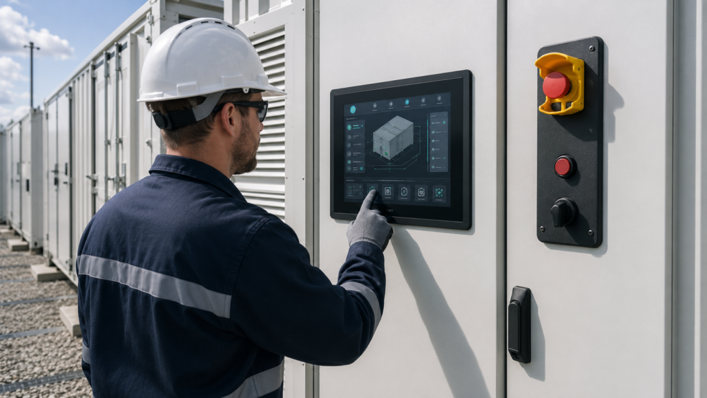
의도된 현장 서비스 장비를 착용한 사용자의 의도적인 탭, 가장자리 대상, 사용되는 드래그, 거부된 접촉, 시동 동작, 통신 복구 및 성능을 평가하십시오. 데이터 입력이 필요한 경우 선택된 화면 크기에서 가상 키보드가 계속 사용 가능한지 확인하십시오.
전용 비상, 차단 또는 기타 안전 관련 제어는 TFT에 그래픽 버튼을 배치하는 것만으로 대체되어서는 안 됩니다. 정지된 애플리케이션, 고장난 터치 컨트롤러, 가려진 화면, 통신 손실 또는 디스플레이 링크 고장은 화면상의 제어에 영향을 미칠 수 있습니다. 안전 책임은 독립적으로 설계되고 검증된 BESS 아키텍처에 속합니다.
인클로저 개구부, 커버 렌즈, 밀봉 개념, 패널 장착, 케이블 글랜드, 커넥터 접근, FPC 굽힘 반경, 스트레인 릴리프, 서비스 여유 공간, 접지, 차폐, 배수, 결로 위험 및 디스플레이와 HMI 전자장치에서 발생하는 열을 검토하십시오.
LCD 모듈 단독으로는 침투 보호 등급을 설정하지 않습니다. 모든 밀봉 또는 환경 등급은 정의된 완성 어셈블리 및 테스트 구성에 적용됩니다. 디스플레이에 부착된 커버 렌즈는 장비를 자동으로 방수, 방진, 내식성 또는 해안가 설치에 적합하게 만들지 않습니다.
온도 요구 사항은 태양열 부하, 캐비닛 열, 대기 조건, 저온 시동, 백라이트 작동 및 주변 전력 전자장치를 포함한 디스플레이의 실제 위치를 기준으로 해야 합니다. 일반적인 옥외 공기 온도를 내부 설치 환경을 측정하거나 추정하는 대신 사용하지 마십시오.
전력 변환, 스위칭 소자, 접촉기, 통신, 긴 케이블 및 접지 구성은 전기적으로 까.
A local display may remain powered even when its connection to the BMS, PCS, EMS, or site network is unavailable. The HMI should not present old data as though it were current. Define how the application represents unavailable, delayed, invalid, or partially updated information.
Review timestamps, communication-state indicators, subsystem availability, blank or retained values, alarm acknowledgement, and recovery after reconnection. The correct behavior depends on the system architecture; the TFT LCD cannot determine whether a value is trustworthy.
Startup sequencing should cover panel power, display-interface initialization, backlight enable, HMI-host boot, touch-controller availability, application launch, user authentication, network connection, and receipt of valid equipment data. Acceptance criteria should define what appears at every stage.
Repeated power cycling, incomplete startup, HMI application restart, network interruption, controller restart, and restoration of current equipment context should be included in system testing.
Validation should progress from electrical bring-up to the intended display, touch stack, host, active controller where used, cables, power supply, enclosure, grounding, software, and BESS integration environment.
Use representative screens and workflows. Check outdoor readability, night dimming, viewing positions, gloved touch, alarm navigation, permissions, data-age presentation, communication loss, startup, restart, and recovery. Confirm that dedicated physical controls remain distinct from ordinary graphical functions.
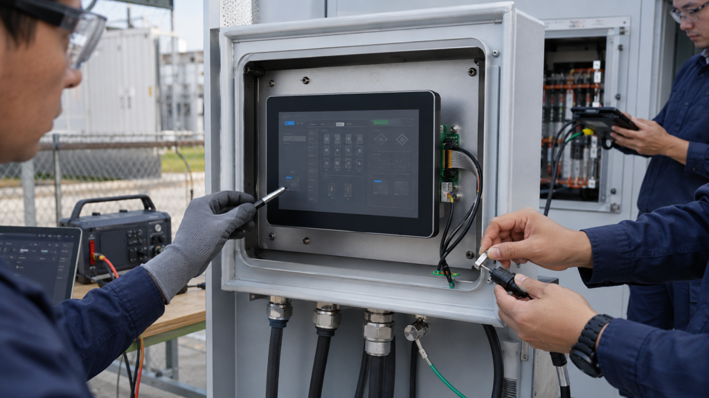
Mechanical validation can include cover alignment, active-area visibility, sealing interfaces, cable retention, FPC routing, connector access, service replacement, strain relief, cabinet-door movement, and thermal behavior. Environmental or ingress claims require the applicable completed-assembly test; they cannot be inferred from a display-module description.
Write measurable acceptance criteria before design freeze. Terms such as “sunlight readable,” “outdoor,” “glove touch,” “real time,” “waterproof,” or “industrial grade” are incomplete without a defined environment, content, user condition, test method, system boundary, and required result.
Provide the target active area, enclosure drawing, mounting position, orientation, cover concept, representative GUI, viewing conditions, host processor or board, native display outputs, operating system, touch requirements, cable constraints, power sequence, environmental conditions, service workflow, project stage, and expected demand range.
Identify the requested delivery boundary: a TFT LCD module, LCD-and-touch assembly, covered display assembly, LCD with an active video controller, embedded computing platform, or more complete HMI subsystem. These deliverables require different hardware, firmware, mechanical, and compatibility information.
RJY Display can review applicable existing display platforms and project-specific customization involving touch, cover construction, backlight, FPC, interface, controller board, and mechanical coordination. Feasibility depends on the selected platform and confirmed project requirements. This does not imply that any arbitrary LCD cell size can be created from zero or that RJY qualifies the complete BESS.
Contact RJY Display for a BESS local HMI display review 디스플레이 레이어를 평가하는 데 필요한 광학, 전기, 터치, 호스트, 인클로저, 환경 및 워크플로 정보를 제공하십시오.
아닙니다. TFT LCD는 픽셀을 표시합니다. 완전한 BESS HMI에는 호스트 컴퓨터 또는 컨트롤러, 애플리케이션 소프트웨어, 입력 장치, 통신, 전원, 인클로저 통합, 그리고 더 큰 시스템에 대한 정의된 연결도 필요합니다.
아닙니다. 로컬 HMI는 선택된 정보를 표시하고 허용된 사용자 입력을 보고할 수 있지만, 배터리 관리, 전력 변환, 에너지 관리 및 감독 제어는 완성된 BESS 아키텍처 내에서 별도의 기능으로 유지됩니다.
아닙니다. 그래픽 제어는 디스플레이, 터치, 소프트웨어, 전원 또는 통신 오류의 영향을 받을 수 있습니다. 안전 관련 및 비상 기능은 독립적으로 설계되고 검증된 시스템 아키텍처가 필요합니다.
No. A passive cable cannot convert HDMI into a raw MIPI, RGB, LVDS, or eDP panel interface. A compatible active controller or bridge is required and must support the source and exact panel requirements.
인클로저 및 활성 영역 타겟, 대표 GUI, 장착 및 조명 조건, 호스트 플랫폼, 기본 디스플레이 출력, 운영 체제, 터치 및 커버 요구 사항, 케이블 및 전원 제약, 환경 조건, 프로젝트 단계 및 예상 수요 범위를 제공하십시오.
디스플레이 크기, 해상도, 인터페이스, 밝기, 터치 요구 사항, 컨트롤러 보드 요구 사항 및 적용 환경을 공유해 주십시오.
관련 디스플레이 기술 가이드 및 응용 참고 자료를 계속 읽어보십시오.