Vous rencontrez un goulot d'étranglement dans votre projet d'affichage embarqué ?
Ne laissez pas l'intégration complexe ou les problèmes de chaîne d'approvisionnement ralentir votre mise sur le marché. Réservez une consultation gratuite avec l'équipe d'experts RJY pour un accompagnement sur mesure en conception et fabrication.
Comment choisir un écran LCD rond pour les produits OEM
Publié :
Lecture de 14 minutes
Mis à jour :
Un écran LCD rond peut soutenir une architecture produit difficile à réaliser avec un écran rectangulaire conventionnel. Les panneaux de commande circulaires, les interfaces de type instrument, les appareils rotatifs, les équipements liés aux véhicules, les terminaux domotiques et les IHM spécialisées peuvent tous bénéficier d’un affichage qui épouse la forme du produit.
La forme ne simplifie pas la sélection technique. Un écran rond doit néanmoins s’intégrer dans le boîtier, présenter les informations requises, se connecter à l’hôte réel, fonctionner avec les circuits d’alimentation et de rétroéclairage disponibles, prendre en charge le comportement tactile prévu et rester identifiable lors de l’échantillonnage et de la production.
Un processus de sélection fiable commence par l’exigence produit complète. La taille diagonale et la résolution sont des filtres utiles, mais elles ne déterminent ni la géométrie visible, ni la compatibilité d’interface, ni l’ajustement mécanique, ni l’utilisabilité de l’interface, ni l’adéquation environnementale.
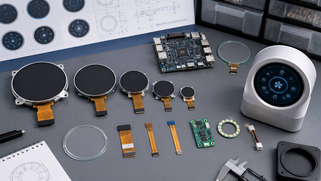
Sélection d’un écran LCD rond avec tactile, verre de protection, carte hôte, FPC, rétroéclairage, interface utilisateur et boîtier
Définir d’abord ce que signifie “ écran LCD rond ”
Plusieurs structures différentes peuvent être décrites comme un écran LCD rond. La surface avant peut apparaître circulaire tandis que le verre LCD, le cadre du rétroéclairage ou la matrice de pixels reste carré ou approximativement rectangulaire. Un autre assemblage peut utiliser un verre de protection circulaire au-dessus d’une ouverture d’affichage conventionnelle.
Terme géométrique
La zone physique dans laquelle les pixels produisent une image
Pourquoi c'est important
Zone active
Zone contenant les pixels adressables
Détermine la taille physique de l’image et la surface visible de l’interface utilisateur
Zone visible ou zone de visualisation
Zone destinée à rester visible à travers le cadre ou le verre de protection
Définit où le texte, les indicateurs et les commandes peuvent être vus
Contour du verre LCD
Dimensions complètes de la cellule LCD
Affecte le dégagement du boîtier et le montage
La largeur, la hauteur et l'épaisseur complètes de l'ensemble d'affichage
Enveloppe du LCD, du rétroéclairage, du cadre, de l’adhésif et des composants arrière
Détermine si l’assemblage complet s’adapte
Zone active tactile
Zone du capteur dans laquelle l’entrée est détectée
Doit s’aligner avec les commandes affichées et le système de coordonnées
Les dimensions externes de la lentille lorsque la vitre de protection est incluse
Lentille avant finie visible par l’utilisateur
Affecte l’apparence, le collage, l’ajustement du boîtier et le comportement tactile
Ne pas supposer que chaque pixel à l’intérieur d’un framebuffer de résolution carrée reste visible. Demander un dessin mécanique contrôlé identifiant la zone active, la limite de visualisation, le contour du verre, le contour du module, le FPC, les composants, le capteur tactile et le verre de protection.
Commencer par l’interface utilisateur et l’architecture du produit
Un écran rond doit être sélectionné parce qu’il soutient l’architecture d’interaction et mécanique du produit, et non seulement parce qu’il crée une apparence distinctive.
Documenter les informations et les commandes auxquelles l’utilisateur doit accéder :
État opérationnel persistant, valeurs, avertissements et indicateurs de connexion
Actions principales et paramètres fréquemment ajustés
Texte, icônes, graphiques, animations, images ou vidéo
Langues requises et traductions les plus longues
Entrée au doigt nu, avec gants, stylet, encodeur, bouton ou mixte
Distance de visualisation, angle de montage, orientation et lumière ambiante
États de démarrage, d’attente, de panne, de maintenance, de mise à jour et de récupération
Préparer des écrans représentatifs à la taille physique prévue avant de choisir le module. Un écran de cadran visuellement attrayant peut encore échouer lorsque des avertissements, du texte traduit, des cibles tactiles ou des informations de diagnostic doivent tenir dans la limite circulaire.
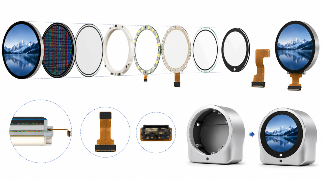
Zone active LCD rond, zone de visualisation, contour du module, capteur tactile, verre de protection, rétroéclairage et FPC
Comparer le diamètre actif et l’encombrement du module avant la taille diagonale
La taille diagonale est particulièrement facile à mal interpréter pour un écran rond. Elle peut se référer à la classe du panneau, au diamètre actif ou à une autre dimension définie par le fabricant. Deux modules vendus sous la même taille nominale peuvent avoir des zones actives, des bordures, des contours de verre, des cadres, des positions de FPC et des épaisseurs différents.
Contrôle mécanique
Statut d'équipement sur une ligne
Diamètre visible
Quelle zone circulaire doit rester visible à travers le cadre final et le verre de protection ?
Contour du LCD et du module
La cellule, le rétroéclairage, le cadre, l’adhésif et les composants peuvent-ils s’adapter derrière l’ouverture avant ?
**Épaisseur**
La valeur indiquée inclut-elle le tactile, le verre de protection, l’adhésif, le cadre et les composants arrière ?
Alignement central
La zone active, la zone tactile, l’ouverture du verre de protection et le boîtier sont-ils concentriques dans la tolérance cumulée ?
Sortie du FPC
La nappe peut-elle atteindre le PCB sans entrer en conflit avec la conception avant symétrique ?
Montage et support
Quelles régions peuvent être supportées ou collées sans charger le verre actif ?
Examiner le dessin du fournisseur avec le CAD du boîtier et le placement du PCB. Une ouverture avant circulaire ne rend pas l’assemblage interne symétrique en rotation.
Sélectionner la résolution en fonction de l’interface utilisateur et des capacités de l’hôte
Les écrans ronds utilisent couramment des matrices de pixels carrées car un framebuffer carré peut contenir une image visible circulaire. D’autres produits peuvent utiliser une matrice de pixels qui n’est pas parfaitement carrée. La limite visible exacte et le comportement des pixels doivent provenir de la documentation actuelle de l’affichage.
Le choix de la résolution doit prendre en compte :
Exigence
Engineering Impact
Le texte et les indicateurs les plus petits
Détermine si une résolution physique suffisante en pixels est disponible
La densité d'information
Contrôle la quantité d'informations d'état et de commande pouvant rester visibles
La charge de travail graphique
Affecte le rendu, la mémoire du framebuffer, la bande passante de transfert et la charge de l'hôte
La localisation
Peut nécessiter un espace supplémentaire, des polices, de la mémoire de glyphes et un retour à la ligne
Augmente les exigences graphiques, de mémoire, de bande passante et de logiciel
Nécessite des tests représentatifs du processeur, de la mémoire, de l'interface et de la pile logicielle
L'orientation native
Affecte le timing du panneau, la disposition des applications, les coordonnées tactiles et les graphiques de démarrage
Utilisez le Calculateur de paramètres d'écran LCD TFT comme aide initiale pour les calculs d'affichage physique. L'approbation finale doit néanmoins utiliser la fiche technique actuelle du panneau, les maquettes UI réelles et le matériel cible.
Concevoir une zone de sécurité d’interface utilisateur circulaire
Un canevas de pixels carrés ne signifie pas que le contenu critique doit utiliser les coins. Définissez une zone de sécurité spécifique à l'application à l'intérieur du cercle visible et conservez le texte essentiel, les cibles tactiles, les symboles d'avertissement et la navigation à l'intérieur de celle-ci.
La marge requise dépend de la limite visible réelle, du cadre, de l'impression du verre de protection, de l'alignement tactile, de la police, de la taille des commandes, de la précision de montage et du flux de travail utilisateur. N'appliquez pas un pourcentage universel à chaque écran rond.
Élément d'interface utilisateur
Examen de l'écran rond
Statut principal
Maintenez-le visible sans obliger l'utilisateur à interpréter un contenu tronqué dans les coins
Texte
Testez la longueur des lignes, le retour à la ligne, la taille physique et les traductions à l'intérieur de la limite circulaire
Commandes tactiles
Confirmez que la cible complète reste dans la zone visible et détectable de manière fiable
Arcs et jauges
Vérifiez que les échelles, les étiquettes, les points d'extrémité et les zones d'avertissement restent lisibles
Boîtes de dialogue et claviers
Évaluez si les composants rectangulaires nécessitent une disposition spécifique aux écrans ronds
Écrans système
Incluez les écrans de démarrage, de mise à jour, de récupération, d'autorisation et d'erreur dans l'examen de la disposition ronde
Android prend en charge un qualificatif de ressources qui distingue les écrans ronds des écrans non ronds, montrant que la forme de l'écran peut nécessiter des ressources de disposition spécifiques à la plateforme plutôt qu'un simple redimensionnement.[5] Un système Linux embarqué, RTOS ou MCU peut utiliser une implémentation différente, mais le même principe d'ingénierie s'applique : l'application doit comprendre la forme visible réelle.
Adapter l’interface d’affichage à l’hôte réel
La catégorie publique actuelle d'affichages ronds de RJY Display comprend des chemins de produits utilisant RGB, RGB plus SPI, MIPI DSI et LVDS.[1] Ces noms d'interface ne sont pas interchangeables et ne prouvent pas indépendamment la compatibilité avec une carte hôte.
Route d'interface
Contexte potentiel du projet
Éléments à confirmer
RGB avec SPI de contrôle
Systèmes MCU ou processeurs d'application avec un contrôleur d'affichage parallèle implémenté
Largeur de données, horloge de pixels, synchronisation, tension, initialisation, brochage, mémoire et routage PCB
MIPI DSI
Processeurs ou cartes pont avec un hôte DSI pris en charge
Lignes implémentées, plage de fonctionnement des lignes, mode, format de pixels, timing natif, commandes, alimentation et pilote du panneau
LVDS
Panneaux embarqués plus grands et architectures de cartes contrôleurs prises en charge
Configuration des canaux, mappage, horloge, affectation des couleurs, tension, connecteur, câble et timing
Carte contrôleur active
Un hôte fournit HDMI ou un autre mode vidéo standard tandis qu'un contrôleur pilote le panneau brut
Mode d'entrée, mise à l'échelle, sortie du panneau, firmware, initialisation, rétroéclairage, alimentation et chemin de retour tactile
La MIPI Alliance définit MIPI DSI comme une interface série haute vitesse entre un processeur hôte et un module d'affichage.[3] Une étiquette DSI partagée nécessite toujours un accord sur l'implémentation physique, le timing, le mode de fonctionnement, les commandes, l'alimentation et le logiciel.
L'exemple de système d'affichage DSI de NXP configure séparément le timing natif, l'alimentation du panneau, la réinitialisation, le contrôle du rétroéclairage, les horloges, la polarité des signaux et l'interface d'affichage.[2] Faire correspondre uniquement l'interface ou la résolution est donc insuffisant.
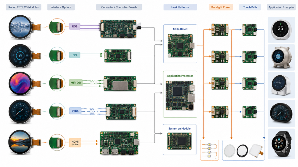
Chemins RGB, MIPI DSI, LVDS, carte contrôleur, tactile et rétroéclairage pour l'intégration d'écrans LCD ronds
Commencer par la carte réelle, et non par la brochure du processeur
Un processeur peut contenir un contrôleur d'affichage que la carte finale ne route pas vers un connecteur. La carte peut également manquer des rails de tension corrects, des GPIO, du circuit de rétroéclairage, du pilote de panneau ou de la configuration logicielle.
Avant d'approuver un LCD rond, collectez :
Le modèle exact du MCU, du processeur d'application, du module de calcul ou de la carte contrôleur
La révision de la carte, les informations schématiques et la définition du connecteur
La sortie d'affichage implémentée et le timing natif pris en charge
La mémoire disponible et la charge graphique représentative
Circuits d'alimentation, de réinitialisation, d'activation et de rétroéclairage du panneau
Le système d'exploitation, le noyau, le BSP, le bootloader, le RTOS ou la version du SDK MCU
Le pilote de panneau existant et la prise en charge de l'initialisation
L'interface d'entrée tactile et le pilote
La compatibilité doit être démontrée pour la carte, le panneau, le câble et l'image logicielle réels. Une liste d'interfaces au niveau du processeur n'est qu'un point de départ.
Évaluer le tactile comme sous-système distinct
Un LCD rond peut être fourni sans tactile ou coordonné avec une configuration tactile appropriée lorsqu'elle est disponible. Le capteur tactile, le contrôleur, le verre de protection, le collage, le FPC, l'interface hôte et le firmware doivent être évalués séparément du chemin d'image.
Zone tactile
Question de sélection
Géométrie du capteur
La zone tactile active est-elle alignée avec le cercle visible et les commandes requises ?
Contrôleur tactile
Quel contrôleur et quel firmware exacts sont utilisés, et quels contacts et outils d'entrée sont pris en charge ?
Connexion hôte
La carte fournit-elle l'USB, l'I2C, le SPI, la réinitialisation, l'interruption, la tension et le pilote requis ?
Vitre de protection
Les exigences relatives au contour, au diamètre, à l'épaisseur, à l'impression, à l'ouverture, à la zone adhésive et à la surface sont-elles définies ?
Mappage des coordonnées
L'origine, la plage, la mise à l'échelle, la rotation et l'interface utilisateur circulaire correspondent-elles à l'image affichée ?
Environnement
Quelles conditions relatives aux gants, à l'humidité, au nettoyage, au bruit électrique et à la mise à la terre doivent être testées ?
Le guide de conception tactile capacitif de Microchip explique que le revêtement tactile affecte le comportement du capteur et que les exigences mécaniques et électriques doivent être prises en compte dans le cadre de la conception du capteur.[4] Ne supposez pas qu'un verre de protection circulaire sur mesure peut être ajouté sans examiner la configuration du contrôleur de capteur.
Android utilise également les propriétés des périphériques d'entrée et l'étalonnage pour classer, transformer et normaliser le comportement tactile, y compris le mappage des coordonnées tenant compte de l'orientation.[6] Le système tactile final doit être testé avec le verre de protection approuvé, le micrologiciel du contrôleur, le pilote hôte, la rotation, le cadre et le boîtier.
Choisir le rétroéclairage et les performances optiques en fonction de l’environnement
La luminosité doit être sélectionnée en fonction des conditions de visualisation prévues plutôt que maximisée par défaut. Le chemin optique final comprend l'écran LCD, les polariseurs, le capteur tactile, le collage ou la lame d'air, le verre de protection, la bordure imprimée, le traitement de surface, la lumière ambiante, la direction de visualisation et les couleurs de l'interface utilisateur.
Exigence optique
Éléments à évaluer
Lumière ambiante
Position d'installation, réflexions, empilement du verre de protection, distance de visualisation et contenu de l'écran
Sens de visionnement
Position normale de l'utilisateur, utilisation hors axe, rotation, dérive des couleurs et comportement du contraste
Puissance du rétroéclairage
Configuration des LED, circuit de commande, tension, courant, activation, gradation et chaleur
Gradation
Plage de fonctionnement requise, méthode de contrôle, comportement à faible niveau et réponse de l'application
Couverture et collage
Réflexions, apparence, contamination, alignement, adhésif et performance tactile
Ne déduisez pas la lisibilité en plein soleil, l'adéquation à une utilisation extérieure, les performances du collage optique ou une durée de vie universelle de la luminosité annoncée d'un produit. Utilisez des données spécifiques à la configuration et validez l'assemblage complet.
Vérifier le positionnement du FPC, du connecteur et du PCB
La face avant d'un écran rond peut sembler symétrique, mais le FPC et le connecteur créent une orientation définie. Leur emplacement peut déterminer le placement du PCB, le montage, l'accès aux câbles et la maintenabilité.
Examinez les éléments suivants à partir des dessins contrôlés :
Direction de sortie du FPC, longueur, raidisseur, contacts et zone de courbure sécurisée
Pas du connecteur, hauteur, côté contact, direction d'insertion et pièce d'accouplement
Affectations des broches d'affichage, de commande, d'alimentation, de masse, de rétroéclairage et tactiles
Composants arrière et zones d'exclusion
Accès au connecteur PCB pendant l'assemblage
Dégagement par rapport aux fixations, bords, sources de chaleur, antennes et composants mobiles
Détente de traction, maintien, assemblage répété et procédure de maintenance
Un nombre de connecteurs correspondant ne prouve pas une attribution des broches correspondante. Un adaptateur peut réacheminer des signaux compatibles, mais il ne peut pas ajouter un contrôleur d'affichage non pris en charge, créer des voies manquantes, corriger une tension incompatible ou remplacer un micrologiciel absent.
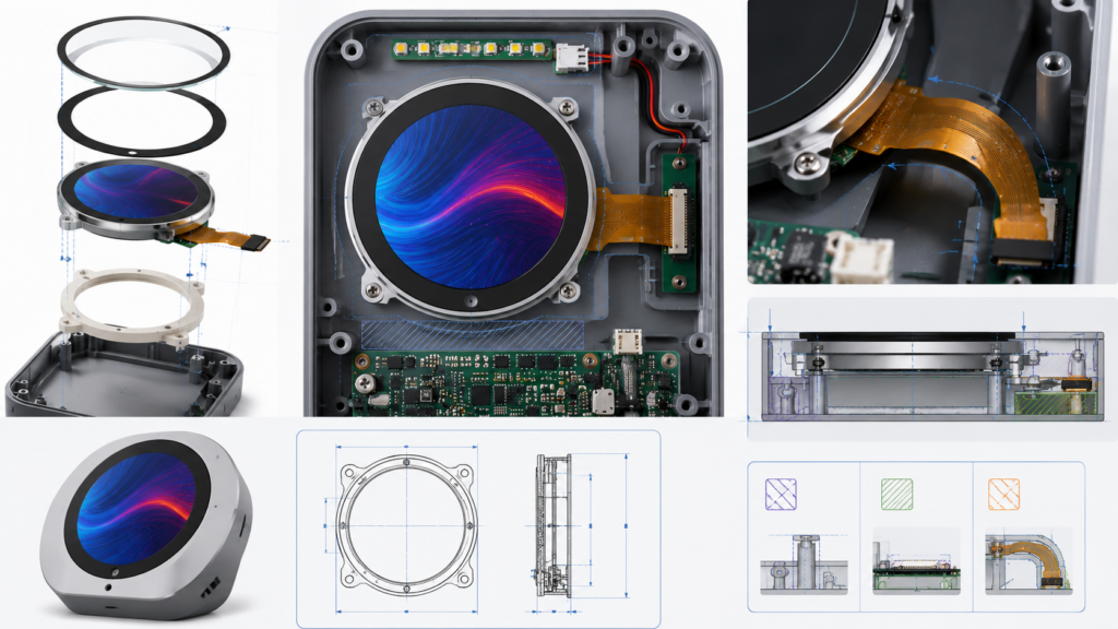
Intégration mécanique d'un écran LCD rond, FPC, connecteur, PCB, verre de protection, supports et boîtier
Traduire les exigences applicatives en exigences testables
Des termes tels que écran rond industriel, affichage automobile, HMI extérieur et écran médical ne définissent pas des spécifications universelles. Convertissez l'étiquette d'application en exigences mesurables pour l'équipement fini exact.
Domaine environnemental
Exigence à définir
Température
Limites de fonctionnement et de stockage, condition de démarrage, durée et comportement acceptable de l'affichage et du tactile
Humidité et nettoyage
Exposition, responsabilité d'étanchéité, agents de nettoyage, fréquence, comportement tactile, impression et adhésifs
Vibrations et chocs
Montage, axes, profil, durée, état de fonctionnement, configuration de l'échantillon et critères d'acceptation
Conditions électriques
Qualité de l'alimentation, mise à la terre, câbles, exigences CEM ou d'immunité, boîtier et état de fonctionnement
Charge mécanique
Pression sur le verre de protection, déformation du boîtier, contrainte de l'adhésif, fixations et surfaces de support
Contexte réglementaire
Normes applicables au produit fini, partie responsable, configuration exacte et preuves requises
Ne déduisez pas une qualification automobile, une certification médicale, un indice IP, une résistance chimique ou un grade environnemental de la forme de l'écran, du titre du produit, de la technologie du panneau ou de l'application prévue.
Commencer par une plateforme d’écran LCD rond existante
RJY Display's Catégorie d'écrans ronds fournit des chemins de produits existants pour l'examen initial. La gamme publique actuelle comprend des modules RGB compacts, des options MIPI, des configurations tactiles et des produits LVDS ou MIPI plus grands.[1]
Évaluation de processeur d'application MIPI plus grand
Voies, mode, synchronisation, initialisation, support de carte, alimentation et mécanique
Ces liens sont des chemins de découverte de produits, et non des approbations automatiques de compatibilité. Les spécifications publiques doivent être vérifiées par rapport aux documents contrôlés les plus récents et à l'état actuel de l'approvisionnement avant l'échantillonnage.
Définir la personnalisation autour du module existant
Lorsque la plateforme centrale d'écran LCD rond est appropriée, un projet peut évaluer les changements environnants tels que :
Domaine de personnalisation
Portée possible du projet
Contrôle requis
Vitre de protection
Exigences relatives au contour, à l'ouverture, à l'impression, à l'épaisseur, aux bords et à la surface
Dessin maîtrisé, matériau, tolérances, critères d'apparence et validation tactile
Écran tactile
Capteur, contrôleur, empilement de la vitre de protection, collage, FPC et connexion hôte
Contrôleur exact, firmware, pilote, coordonnées, environnement et approbation d'échantillon
Rétro-éclairage
Objectif de luminosité, activation, gradation, alimentation et coordination du pilote
Validation électrique, optique, thermique et mécanique
FPC et interface
Direction de la queue, connecteur, routage des broches, câble ou coordination de la carte
Dessins électriques et mécaniques, outillage, firmware et tests d'échantillons
Carte contrôleur
Sélection ou adaptation de la carte autour du panneau confirmé
Révision réelle de la carte, interface, synchronisation, firmware, prise en charge tactile et rétroéclairage
Firmware
Initialisation du panneau, synchronisation, orientation de l'interface utilisateur, tactile, démarrage, veille et réveil
Plateforme nommée, livrables, révisions, propriété et tests d'acceptation
Structure mécanique
Vitre de protection, cadre, support, boîtier, position du PCB et routage des câbles
CAO, cumul des tolérances, plan d'assemblage, outillage et validation complète des échantillons
Cette voie de personnalisation commence par un module d'affichage existant. Elle ne doit pas être interprétée comme la capacité de créer arbitrairement un diamètre, une résolution ou une nouvelle architecture de panneau rond à partir de zéro.
Utiliser une matrice de comparaison des écrans LCD ronds
Domaine de décision
Candidat A
Candidat B
Preuves requises
Modèle et révision
Enregistrement
Enregistrement
Fiche technique et dessin actuellement contrôlés
Géométrie visible
Comparer
Comparer
Zone active, zone de visualisation, ouverture de la vitre et graphisme de l'interface utilisateur
Enveloppe du module
Comparer
Comparer
Dimensions du LCD, du rétroéclairage, du cadre, des composants, du FPC, du tactile et de la vitre de protection
Résolution et interface utilisateur
Évaluer
Évaluer
Prototype physique, polices, traductions, commandes et états système
Interface et temporisation
Confirmer
Confirmer
Implémentation au niveau de la carte, synchronisation native, brochage et firmware
Toucher
Confirmer
Confirmer
Capteur, contrôleur, vitre, coordonnées, pilote et tests d'entrée requis
Rétroéclairage et optique
Évaluer
Évaluer
Données de configuration et test de visualisation du produit fini
Ajustement mécanique
Évaluer
Évaluer
CAO de l'affichage, du PCB, du câble, de la vitre et du boîtier
Environnement
Évaluer
Évaluer
Exigences spécifiques à l'application et preuves spécifiques à la configuration
Cycle de vie
Confirmer
Confirmer
Révision, substitution, firmware, PCN, fin de vie et processus de requalification
Un candidat à moindre coût ne doit pas réussir la comparaison lorsque l'interface hôte, la géométrie visible, le contrôleur tactile, le dessin mécanique, le firmware ou le cycle de vie restent indéfinis.
Valider l’échantillon complet d’affichage rond
Zone de validation
Examen minimal
Géométrie visible
Cercle actif, cadre, impression de la vitre, alignement central, pixels tronqués et cumul des tolérances
UI
Texte, icônes, jauges, boîtes de dialogue, avertissements, traductions, écrans de démarrage, de mise à jour, d'erreur et de récupération
Image d'affichage
Synchronisation native, motifs plein écran, orientation, comportement des couleurs, démarrage, veille, réveil et redémarrages répétés
Toucher
Centre, circonférence, bords, rotation, outils d'entrée requis, vitre de protection, réveil et comportement anti-faux contacts
Charge de travail de l'application
Graphismes représentatifs, communication, stockage, réseau, périphériques et activité en arrière-plan
Rétroéclairage et alimentation
Activation, gradation, niveau de fonctionnement prévu, coupure d'alimentation, courant et température du boîtier
Assemblage mécanique
Alignement, support, routage du FPC, accès au connecteur, maintien, adhésif, câble et procédure de maintenance
Environnement
Conditions définies de lumière ambiante, température, humidité, nettoyage, conditions mécaniques et électriques
Enregistrement de configuration
LCD, tactile, vitre, FPC, câble, carte, firmware, circuit de rétroéclairage, boîtier et problèmes ouverts
Approuver la configuration matérielle et logicielle complète plutôt que uniquement le modèle LCD rond. Une modification ultérieure de la révision de l'affichage, du circuit intégré pilote, du contrôleur tactile, de la vitre de protection, de la carte, du firmware, du câble, du rétroéclairage ou du boîtier peut nécessiter une nouvelle validation.
Quels éléments envoyer pour une revue d’écran LCD rond
Fournir les informations suivantes pour une recommandation et un devis utiles :
Produit cible, utilisateurs, flux de travail et marchés de destination
Diamètre visible requis, zone active, résolution, orientation et encombrement du module
Graphisme d'interface utilisateur représentatif à pleine échelle et états système requis
MCU, processeur, carte de contrôle, module de calcul ou source vidéo exacts
Interface d'affichage implémentée, connecteur, synchronisation native et plateforme logicielle
Technologie tactile, outils d'entrée, contrôleur, interface hôte et exigences de contact
Dessin de la vitre de protection, épaisseur, impression, surface et exigences de collage
Lumière ambiante, directions de visualisation, rétroéclairage, gradation et exigences d'alimentation
Direction du FPC, position du connecteur, placement du PCB et contraintes de câble
Environnement de fonctionnement et tests spécifiques à la configuration requis
Dessin mécanique ou CAO du boîtier
Prototype, pilote, production et quantités annuelles prévues
Cycle de vie, notification de changement et attentes de remplacement
Documentation d'affichage existante lors du remplacement d'un autre module
Demander une revue de compatibilité d’écran LCD rond
RJY Display peut examiner une plateforme LCD ronde existante par rapport à votre zone visible, interface utilisateur, carte hôte, interface, tactile, vitre de protection, rétroéclairage, FPC, firmware, alimentation, environnement et exigences mécaniques.
Un écran LCD rond est un module conçu pour présenter une image visible circulaire ou pour supporter une conception de panneau avant circulaire. La zone active, la zone de visualisation, le verre LCD, le contour du module, le capteur tactile et la vitre de protection peuvent avoir des formes différentes, la structure exacte doit donc être confirmée à partir du dessin mécanique.
Un LCD rond a-t-il toujours une matrice de pixels circulaire ?
Non. De nombreux écrans ronds utilisent une matrice de pixels carrée ou un framebuffer avec une zone visible circulaire. D'autres modules peuvent utiliser une structure de pixels actifs différente. Confirmez la zone active, la limite visible, la résolution et le comportement des coins pour le modèle exact.
Puis-je remplacer un écran LCD rectangulaire par un écran LCD rond de même diagonale ?
Pas automatiquement. La zone active, le diamètre visible, le contour du module, la résolution, l'interface, le synchronisme, le brochage, l'alimentation, le rétroéclairage, le tactile, le micrologiciel, le FPC et le boîtier peuvent tous différer. L'interface utilisateur et la structure mécanique nécessitent normalement une nouvelle revue de compatibilité.
Quelle interface est la meilleure pour un écran LCD rond ?
Il n'existe pas d'interface universellement meilleure. Choisissez en fonction de la carte hôte réelle, du synchronisme natif du panneau, de la résolution, de la charge graphique, du connecteur, du PCB, du micrologiciel, de l'alimentation et des exigences de cycle de vie. Les voies RGB, MIPI DSI, LVDS et carte contrôleur active engendrent des travaux d'intégration différents.
Un écran LCD rond peut-il inclure un écran tactile et une vitre de protection personnalisée ?
Cela est possible lorsqu'une configuration affichage-tactile adaptée est disponible. Le capteur, le contrôleur, le contour de la vitre de protection, l'épaisseur, l'impression, le collage, le FPC, l'interface hôte, le micrologiciel, le mappage des coordonnées, le boîtier et les conditions de fonctionnement requises doivent être évalués ensemble.
Quelles informations sont nécessaires pour un devis d'écran LCD rond ?
Fournissez l'application, le diamètre visible, la résolution, l'enveloppe du module, les graphiques de l'interface utilisateur, la carte hôte, l'interface, les exigences tactiles et de vitre de protection, les besoins en rétroéclairage et en alimentation, les contraintes FPC et connecteur, l'environnement, le dessin du boîtier, les exigences de validation, les quantités et les attentes en matière de cycle de vie.
↗
Vous planifiez un projet d'affichage ?
Partagez la taille de votre écran, sa résolution, son interface, sa luminosité, ses exigences tactiles, les besoins en carte contrôleur et l'environnement d'application.