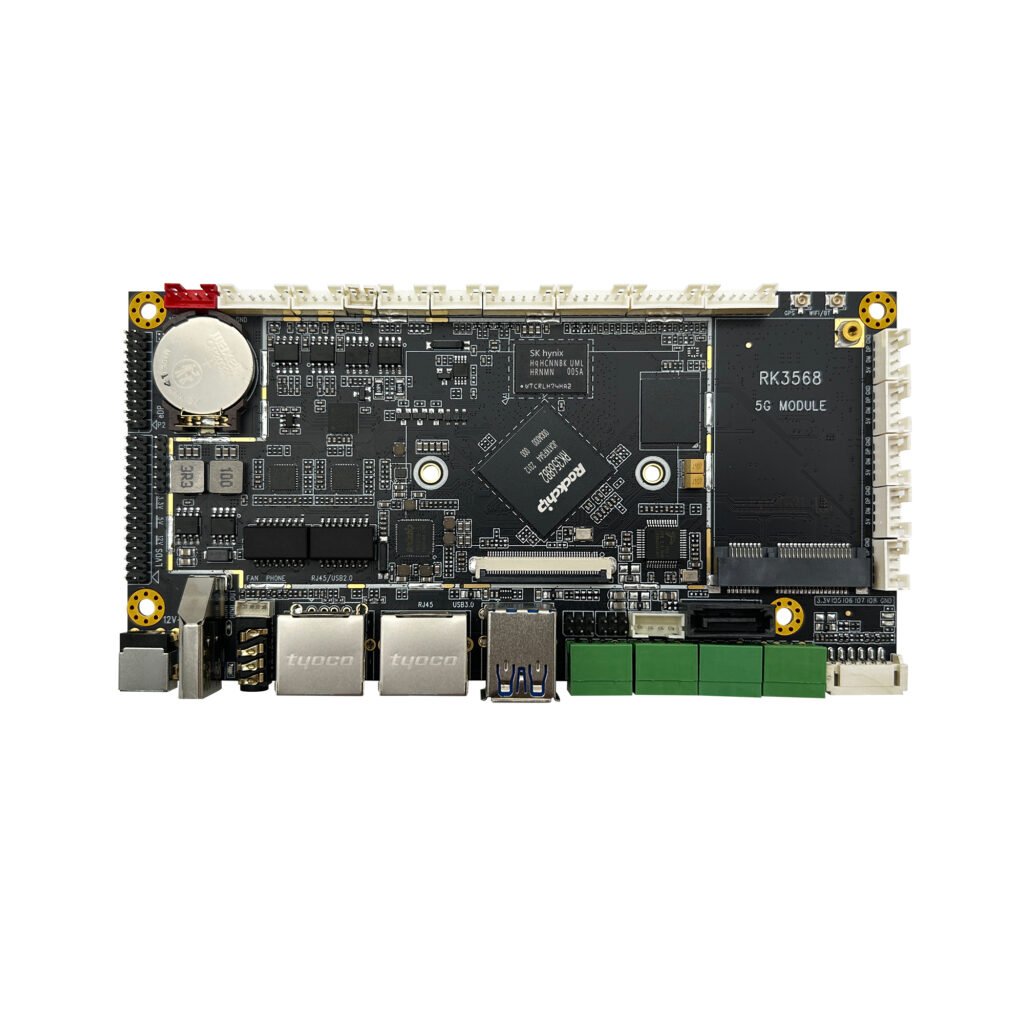
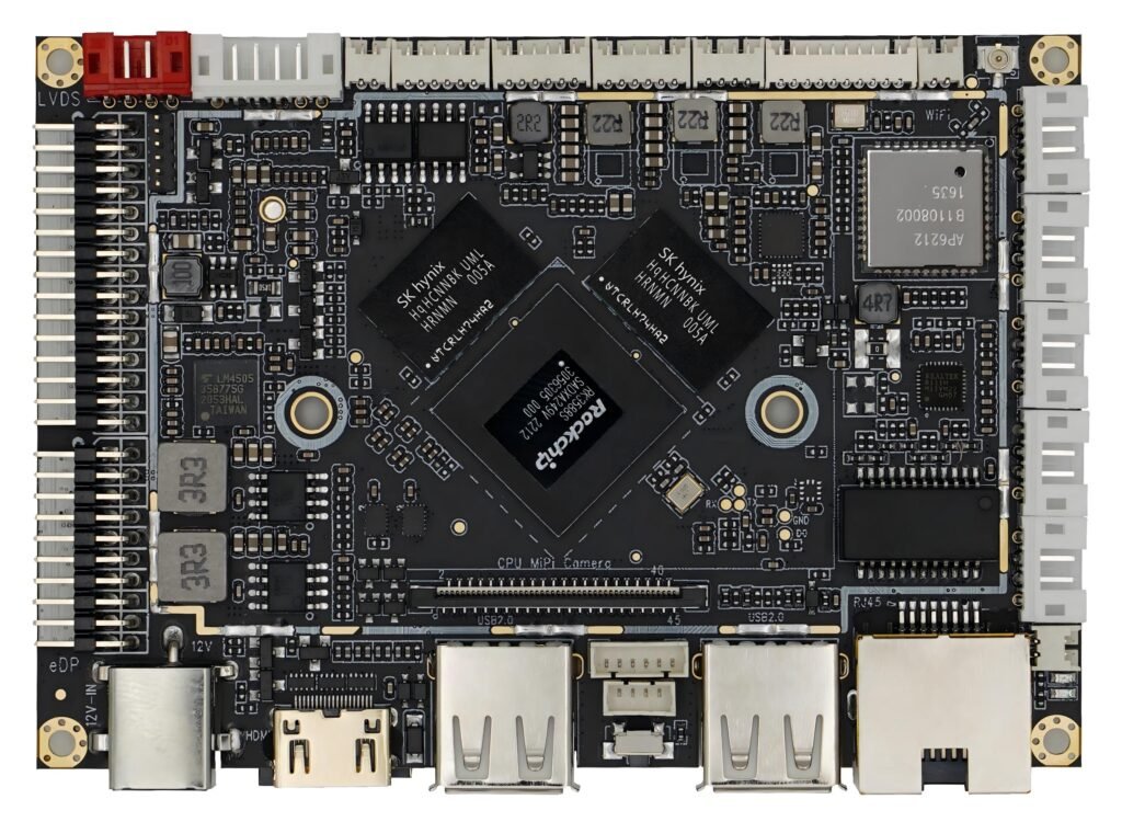
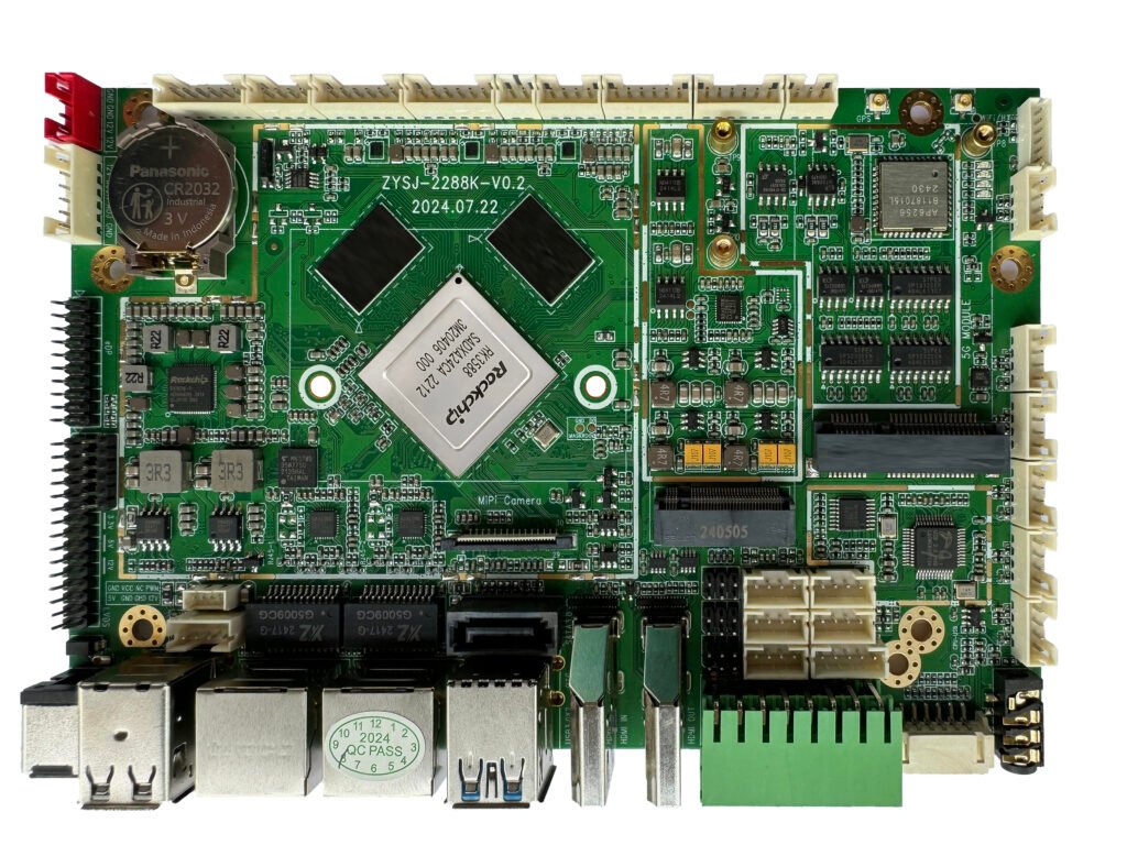
RJY3566M · Embedded Linux & Android

RJY3566MActive model

Rockchip RK3566 Quad-core Android Control Board

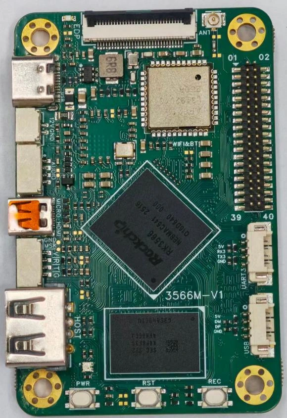
RJY3566M is a compact RK3566 single-board computer for embedded HMI, edge devices and AIoT. It combines Linux and Android options with display, camera, touch and expansion interfaces in a 70 × 45 mm board footprint.

Processor / CPU
Rockchip RK3566 · Quad-core Cortex-A55 · up to 1.8 GHz
NPU
Up to 1.0 TOPS
Memory options
2 / 4 GB LPDDR4x
eMMC storage options
16 / 32 / 64 GB · eMMC 5.1
Operating systems
Ubuntu 20.04 / Debian 11 / Android 11 / Buildroot
Power input
USB Type-C 5 V / 3 A or 2-pin GH1.25 12 V / 2 A
View full specifications ↓
Engineering verification

The supplied RJY3566M datasheet is the primary reference; the earlier website image uses RJY-RK3566M. Its core summary lists 2/4 GB RAM and 16/32/64 GB eMMC, while its hardware table lists 1/2/4/8 GB and 8/16/32/64/128 GB. MicroSD is stated as 2 TB in the summary and 512 GB in the table; confirm the supported limit. The touch connector is labelled both 1.0 mm and 0.5 mm pitch. The GPU and decoder table contains apparent GS2 and H.256 typos. Connector notes retain these discrepancies. No revision number or issue date is printed in the supplied 11-page PDF.

Designed for integration

Product overview.

One platform for Linux and Android projects

RJY3566M combines a quad-core Cortex-A55 processor with Mali-G52 2EE graphics and an NPU specified at up to 1.0 TOPS. The supplied datasheet lists Ubuntu 20.04, Debian 11, Android 11 and Buildroot, giving system developers several software starting points.

Connect displays and peripherals at board level

Choose Micro HDMI, eDP or MIPI DSI for display output. Separate MIPI CSI and I²C touch connectors support camera and touch integration. A 40-pin 1.27 mm GPIO header and a 39-pin high-speed expansion interface expose additional system connections; Ethernet and USB 3.0 are described as expansion signals.

Plan the mechanical and power arrangement

The board measures 70 × 45 × 9.6 mm. The documented power inputs are USB Type-C at 5 V / 3 A and a 2-pin GH1.25 connector at 12 V / 2 A. Use the supplied interface diagrams, mechanical drawing and connector tables to check cable orientation and enclosure fit.

Work from the supplied technical document

The original 11-page Chinese datasheet is available in Technical resources. The English tables below translate its technical content and identify conflicting values or incomplete definitions. Request a confirmed board configuration and revision-matched development package before finalizing integration.

Key features

  • RK3566 quad-core Cortex-A55 up to 1.8 GHz, Mali-G52 2EE graphics and up to 1.0 TOPS NPU.
  • Linux options include Ubuntu 20.04 and Debian 11, alongside Android 11 and Buildroot.
  • Micro HDMI, eDP and MIPI DSI outputs, plus camera and I²C touch connections.
  • 40-pin 1.27 mm GPIO and 39-pin high-speed expansion for system integration.
  • Compact 70 × 45 × 9.6 mm format, with −20 to +70 °C operating range.

Technical reference

Specifications.

Values are model-specific. Review document revisions and any verification notes before integration.

Processor & acceleration

ParameterValueUnitNotes
Processor / CPURockchip RK3566 · Quad-core Cortex-A55 · up to 1.8 GHz—Datasheet pp. 1–2
GPUARM Mali-G52 2EE—Core overview says Mali-G52 2EE; hardware table prints ARM GS2 2EE.
Graphics APIsOpenGL ES 1.1 / 2.0 / 3.2; OpenCL 2.0; Vulkan 1.1; 2D acceleration——
Process technology22nm—
NPUUp to 1.0TOPS—
Video decoding4K at 60 fps; H.264 / VP9 listed—Table also prints H.256, apparently a typo; confirm codec support before design.
Video encoding1080P at 60 fps; H.265 / H.264——
ISP8M ISP with HDR——

Memory & storage

ParameterValueUnitNotes
Memory options2 / 4 GB LPDDR4x—Core summary p. 1. Hardware table lists 1/2/4/8 GB LPDDR4/4X; confirm wider options and installed capacity.
Memory bandwidth (source value)3200MbpsValue stated in core summary; confirm configuration.
eMMC storage options16 / 32 / 64 GB · eMMC 5.1—Core summary p. 2. Hardware table lists 8/16/32/64/128 GB.
MicroSD / TF expansionSystem boot supported; capacity limit requires confirmation—Summary states up to 2 TB, hardware table states up to 512 GB.

Software & BSP

ParameterValueUnitNotes
Operating systemsUbuntu 20.04 / Debian 11 / Android 11 / Buildroot——
SDK / BSP / firmwareThe supplied datasheet lists Linux, Android and Buildroot support with an SDK. Request the board-revision-specific SDK, BSP and firmware; those packages are not attached here.——

Display outputs

ParameterValueUnitNotes
Micro HDMI1080P @ 120 Hz; 4K @ 60 Hz——
eDP2560 × 1600 @ 60 Hz; 30-pin FPC, 0.5 mm pitch——
MIPI DSI1080P @ 60 Hz; 31-pin FPC, 0.3 mm pitch——
Touch connection6-pin I²C touch; 3.3 V signal / supply—Datasheet section 5.3 gives both 1.0 mm and 0.5 mm pitch; confirm mating connector.

Connectivity & expansion

ParameterValueUnitNotes
Wi-Fi / Bluetooth2.4 GHz module—Bluetooth version not specified.
Wi-Fi transmit power16dBm—
USB 2.0Type-A socket and 4-pin 1.25 mm header——
40-pin GPIO2 × 20-pin, 1.27 mm pitch; PWM / I²C / SPI / UART / GPIO——
39-pin expansionUSB 2.0/3.0, 100/1000 Ethernet, SATA, audio, SIM, mini PCIe—Expansion signals listed in the hardware table; carrier/adapter and detailed pinout require confirmation.
Debug serialUART2; 4-pin 1.25 mm latch connector——
User serialUART3; 4-pin 1.25 mm connector——

Camera & audio

ParameterValueUnitNotes
CameraMIPI CSI · 30-pin 0.5 mm FPC · 4-lane——
Camera control signalsMCLK / PWRDN / RESET / I²C4: 1.8 V——
Camera supply pins1.2 V / 1.8 V / 2.8 V / 5 V outputs; see pinout——
AudioRK809-5 · 1.3 W speaker output / microphone input · 4-pin 1.25 mm——

Electrical

ParameterValueUnitNotes
Power inputUSB Type-C 5 V / 3 A or 2-pin GH1.25 12 V / 2 A—Alternative inputs; simultaneous use is not documented.
eDP panel / backlight outputs3.3 V LCD-VCC; 12 V BL-PWR—Current limits are not specified.
ControlsRK809-5 reset; system reset; Recovery button——
IndicatorsRGB LED; 3.3 V power indicator shown in interface map——
ESD test claim±4 kV contact / ±6 kV air—Datasheet claim; separate test report not attached.

Mechanical

ParameterValueUnitNotes
Board dimensions70 × 45 × 9.6mm—

Environmental

ParameterValueUnitNotes
Operating temperature−20 to +70 °C——
Storage temperature−30 to +80 °C——

Board-level integration

Software & interfaces.

Software environment

Operating systems / BSP
Ubuntu 20.04 / Debian 11 / Android 11 / Buildroot
Software / SDK availability
The supplied datasheet lists Linux, Android and Buildroot support with an SDK. Request the board-revision-specific SDK, BSP and firmware; those packages are not attached here.

Connections & peripherals

Display outputs
Micro HDMI 1080P@120Hz / 4K@60Hz · eDP 2560×1600@60Hz · MIPI DSI 1080P@60Hz
Network & USB
2.4 GHz Wi-Fi / Bluetooth · USB 2.0 Type-A / header · Gigabit Ethernet and USB 3.0 via 39-pin expansion
GPIO & expansion
40-pin 1.27 mm GPIO · 39-pin high-speed expansion · UART2 debug / UART3 · MicroSD boot
Camera interface
MIPI CSI · 30-pin 0.5 mm FPC · 4-lane
Audio
RK809-5 · 1.3 W speaker output / microphone input · 4-pin 1.25 mm

Power & mechanical envelope

Power input
USB Type-C 5 V / 3 A or 2-pin GH1.25 12 V / 2 A
Board dimensions (mm)
70 × 45 × 9.6
Operating temperature
−20 to +70 °C
Storage temperature
−30 to +80 °C

Confirm pin assignments, firmware compatibility and the actual board configuration before connection.

Connector-level reference

Connectors & pinout.

Pin definitions from the product technical documentation. Check connector orientation and the notes against your board revision before integration. On smaller screens, swipe a pin table horizontally to see all columns.

eDP display30-pin FPC · 0.5 mm pitch

Datasheet pp. 4–5 · §5.1

Output-current limits and backlight configuration are not specified. Use the PDF photograph to verify pin 1 orientation.

PinSignalFunction / voltage
1NCNot connected
2GNDGround
3EDP-TX-D1NTX lane 1 negative
4EDP-TX-D1PTX lane 1 positive
5GNDGround
6EDP-TX-D0NTX lane 0 negative
7EDP-TX-D0PTX lane 0 positive
8GNDGround
9EDP-TX-AUXPAUX positive
10EDP-TX-AUXNAUX negative
11GNDGround
12LCD-VCC3.3 V output
13LCD-VCC3.3 V output
14NCNot connected
15GNDGround
16GNDGround
17NCNot connected
18GNDGround
19GNDGround
20GNDGround
21GNDGround
22EDP-ENABLEEnable · 3.3 V
23PWM4-EDP-DIMBacklight dimming · 3.3 V
24NCNot connected
25NCNot connected
26BL-PWR12 V backlight output
27BL-PWR12 V backlight output
28BL-PWR12 V backlight output
29BL-PWR12 V backlight output
30NCNot connected
MIPI DSI display31-pin FPC · 0.3 mm pitch

Datasheet p. 5 · §5.1

Pin 21 has no description and pin 23 has a signal/description mismatch in the source. Both are retained for verification. Backlight drive voltage/current is not stated.

PinSignalFunction / voltage
1BL-LEDABacklight anode
2BL-LEDABacklight anode
3BL-LEDABacklight anode
4NCNot connected
5BL-LEDKBacklight cathode
6BL-LEDKBacklight cathode
7BL-LEDKBacklight cathode
8BL-LEDKBacklight cathode
9GNDGround
10GNDGround
11MIPI-DSI-D2PData lane 2 positive
12MIPI-DSI-D2NData lane 2 negative
13GNDGround
14MIPI-DSI-D1PData lane 1 positive
15MIPI-DSI-D1NData lane 1 negative
16GNDGround
17MIPI-DSI-CLKPClock positive
18MIPI-DSI-CLKNClock negative
19GNDGround
20MIPI-DSI-D0PData lane 0 positive
21MIPI-DSI-D0NDescription omitted in source
22GNDGround
23MIPI-DSI-D3PSignal name D3P; source description says lane 2 positive
24MIPI-DSI-D3NData lane 3 negative
25GNDGround
26NCNot connected
27MIPI-DSI-RESETLCD reset · 3.3 V
28NCNot connected
29LCD-VCC3.3 V output
30LCD-VCC3.3 V output
31LCD-VCC3.3 V output
MIPI CSI camera30-pin FPC · 0.5 mm pitch · 4-lane

Datasheet p. 6 · §5.2

PinSignalFunction / voltage
1GNDGround
2MIPI-CSI-D0NData lane 0 negative
3MIPI-CSI-D0PData lane 0 positive
4GNDGround
5MIPI-CSI-CLKNClock negative
6MIPI-CSI-CLKPClock positive
7GNDGround
8MIPI-CSI-D1NData lane 1 negative
9MIPI-CSI-D1PData lane 1 positive
10GNDGround
11MIPI-CSI-D2NData lane 2 negative
12MIPI-CSI-D2PData lane 2 positive
13GNDGround
14MIPI-CSI-D3NData lane 3 negative
15MIPI-CSI-D3PData lane 3 positive
16GNDGround
17MCLK-CSI1.8 V
18GNDGround
19CSI-PWRDN1.8 V
20CSI-RESET1.8 V
21I2C4-SCL1.8 V
22I2C4-SDA1.8 V
23GNDGround
24VCC2V82.8 V output
25GNDGround
26VCC5V05 V output
27VCC1V81.8 V output
28VCC1V21.2 V output
29VCC2V82.8 V output
30VCC5V05 V output
I²C touch6-pin FPC · pitch requires confirmation

Datasheet pp. 6–7 · §5.3

The section bullet states 1.0 mm pitch; its table heading states 0.5 mm. Confirm the connector before selecting a cable.

PinSignalFunction / voltage
1TP-RSTReset · 3.3 V
2TP-VCC3.3 V supply output
3GNDGround
4TP-INTInterrupt · 3.3 V
5TP-I2C1-SDASDA · 3.3 V
6TP-I2C1-SCLSCL · 3.3 V
UART2 debug4-pin · 1.25 mm pitch · latch

Datasheet p. 7 · §5.4

The VCC pin is specified as 5 V output. UART signal voltage is not specified; confirm before connecting an adapter.

PinSignalFunction / voltage
1VCC5 V output
2UART2-RXDebug serial receive
3UART2-TXDebug serial transmit
4GNDGround
UART34-pin · 1.25 mm pitch

Datasheet pp. 7–8 · §5.5

UART signal voltage is not specified.

PinSignalFunction / voltage
1VCC5 V output
2UART3-RXSerial receive
3UART3-TXSerial transmit
4GNDGround
USB 2.0 header4-pin · 1.25 mm pitch

Datasheet p. 8 · §5.6

PinSignalFunction / voltage
1VCC5 V output
2USB DMUSB data negative
3USB DPUSB data positive
4GNDGround
Audio4-pin · 1.25 mm pitch · latch

Datasheet pp. 8–9 · §5.7

PinSignalFunction / voltage
1MICMicrophone input
2GNDGround
3SPK OUTPSpeaker output positive
4SPK OUTNSpeaker output negative
12 V power input2-pin · 1.25 mm pitch · latch

Datasheet p. 9 · §5.8

Hardware table lists 12 V / 2 A. USB Type-C 5 V / 3 A is the other documented input. Simultaneous powering is not documented.

PinSignalFunction / voltage
112V12 V input
2GNDGround
40-pin GPIO expansion2 × 20 pins · 1.27 mm pitch

Datasheet pp. 9–11 · 40Pin header

Pin multiplexing is transcribed as printed. Configure the relevant pinmux in the selected OS/BSP; a 40-pin count alone does not establish compatibility with another board.

PinSignalFunction / voltage
13.3V3.3 V
25V5 V
3GPIO0_B6I2C2_SDA_M0
45V5 V
5GPIO0_B5I2C2_SCL_M0
6GNDGround
7GPIO1_A4GPIO
8NCNot connected
9GNDGround
10NCNot connected
11GPIO3_A1GPIO
12GPIO3_C4PWM14_M0
13GPIO3_A2GPIO
14GNDGround
15GPIO3_A3GPIO
16GPIO3_A4GPIO
173.3V3.3 V
18GPIO3_A5GPIO
19GPIO4_C3SPI3_MOSI_M1
20GNDGround
21GPIO4_C5SPI3_MISO_M1
22GPIO3_A6GPIO
23GPIO4_C2SPI3_CLK_M1
24GPIO3_C6SPI3_CS0_M1
25GNDGround
26GPIO3_A7GPIO
27GPIO3_B6I2C3_SDA_M1
28GPIO3_B5I2C3_SCL_M1
29GPIO3_B0GPIO
30GNDGround
31GPIO3_C2GPIO
32GPIO3_C5PWM15_IR_M0
33GPIO3_B1PWM8_M0
34GNDGround
35GPIO3_B2PWM9_M0
36GPIO3_C3GPIO
37GPIO3_B7GPIO
38GPIO3_B3GPIO
39GNDGround
40GPIO3_B4GPIO
39-pin high-speed expansion39-pin high-speed interface

Datasheet pp. 2–3 · Hardware table / interface map

USB 2.0/3.0, 100/1000 Ethernet, SATA, audio, SIM and mini PCIe are listed. The PDF does not provide the 39-pin signal map or pitch. Request the carrier/adapter design and electrical definitions.

Drawings & technical resources

Product documents.

Before you integrate

Product questions.

Which operating systems are listed in the datasheet?

Ubuntu 20.04, Debian 11, Android 11 and Buildroot are listed. The document states that an SDK is provided; request the package matched to the board revision and target system.

Which memory and storage capacities should I specify?

The core summary lists 2/4 GB LPDDR4x and 16/32/64 GB eMMC 5.1. Its hardware table gives wider ranges. Confirm the installed capacity and supported configuration rather than treating all combinations as separate verified models.

What is the MicroSD capacity limit?

The PDF summary says up to 2 TB, while the hardware table says up to 512 GB and supports system boot. This conflict needs confirmation for the selected card, OS and board revision.

Is there a Gigabit Ethernet socket on the board?

The datasheet lists 100/1000 Ethernet on the 39-pin expansion interface. A carrier or adapter implementation and its pin definitions need confirmation; do not assume an onboard RJ45 socket.

Can I connect any 6-pin touch panel?

No. Confirm I²C wiring, 3.3 V electrical compatibility, pin orientation and the connector. Section 5.3 gives conflicting 1.0 mm and 0.5 mm pitch labels.

Where are the pin definitions and development files?

Connector pin tables are transcribed in the Connectors & pinout tab, and the original 11-page Chinese PDF is available under Technical resources. SDK, BSP and firmware packages have not been uploaded.

Let’s check the fit

Your application.
Our engineering review.

Share your OS, memory, display output, expansion and power requirements for RJY3566M.

  • Application and operating environment
  • OS / BSP, memory and storage configuration
  • Display output, GPIO / serial, camera and network needs
  • Power supply, enclosure and thermal limits
  • Evaluation needs and project timeline
RJY Product Inquiry (#10)

Submit your inquiry to save it with our team. You can also open an email draft after submission. Please read our Privacy Policy.