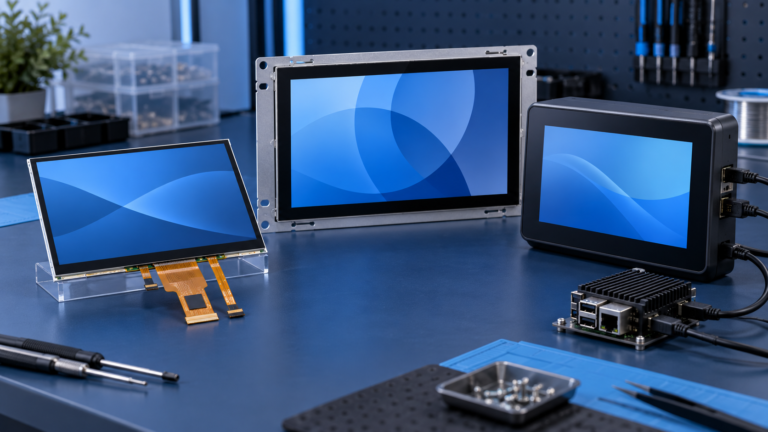
タッチスクリーン付きTFT LCDモジュール:実績ある2026年調達ガイド
2026年のディスプレイ市場をナビゲートしますか?タッチスクリーン付きTFT LCDモジュールに関する究極の調達ガイドをお読みください。カスタム静電容量式タッチスクリーン、サプライチェーンリスク、産業用IC選定のトレンドを発見してください。.
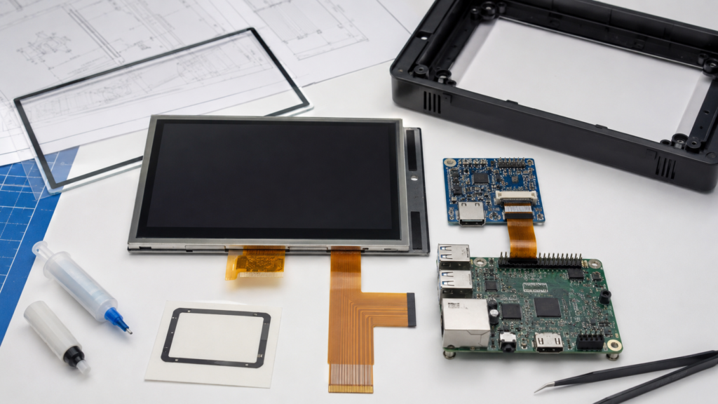
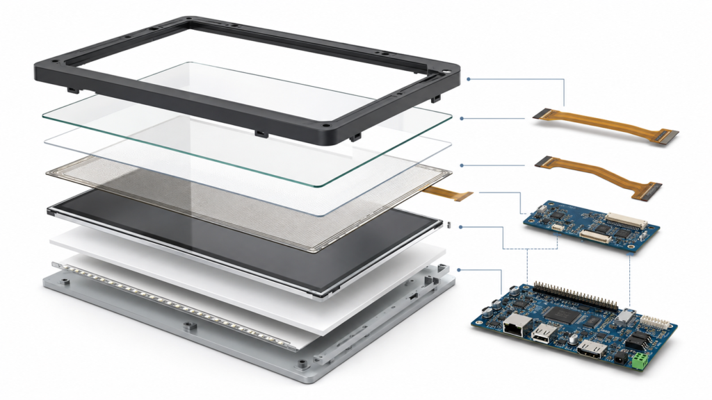
A TFT LCD module with touch screen is not a single interchangeable component. It is a coordinated assembly containing an LCD, touch sensor, touch controller, cover material, bonding structure, display and touch FPCs, host interfaces, drivers, firmware, and mechanical mounting.
This distinction matters during product selection. A display can show the correct image while touch coordinates are rotated. A touch controller can communicate with the host while becoming unreliable behind the final cover glass. A module can fit the front opening while its two FPCs conflict with the PCB or enclosure supports.
The selection process should therefore begin with the application, user input, host platform, and mechanical structure. Capacitive versus resistive touch is important, but it is only one decision within the complete system.

Understand the Complete Touch Display Assembly
The display and touch functions usually follow separate electrical paths. They must be specified individually and then validated together.
| システム要素 | Primary Function | What Must Be Confirmed |
|---|---|---|
| TFT LCDモジュール | Produces the image | Active area, resolution, native timing, interface, power, backlight, FPC, driver IC, and initialization |
| タッチセンサー | Detects a finger, stylus, or other supported input | Technology, active area, electrode structure, supported input tools, cover stack, and environmental behavior |
| タッチコントローラー | Measures the sensor and reports coordinates or touch events | Controller model, firmware, host interface, voltage, interrupt, reset, contact count, and driver support |
| Cover glass or front lens | Provides the finished front surface and protects the sensor | Material, thickness, outline, printing, surface treatment, opening, edge details, and adhesive area |
| 接着構造 | Joins or spaces the LCD, sensor, and cover glass | Bonding method, optical appearance, gap, adhesive, tolerances, rework, and environmental requirements |
| Host system | Drives the image and receives touch input | Display output, touch input, drivers, operating system, orientation, power, sleep, wake, and recovery behavior |
A product described only as a “7-inch capacitive display” leaves most of these decisions undefined. A useful quotation and sample approval must identify the complete configuration.
Choose Between PCAP and Resistive Touch
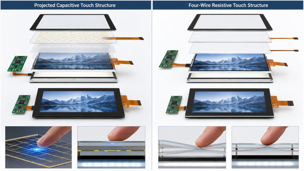
Projected capacitive touch, commonly called PCAP or PCT, and resistive touch use different sensing principles. The correct choice depends on the intended input tool, cover structure, environment, user interface, host software, and validation requirements.
| Decision Area | Projected Capacitive Touch | 抵抗膜方式 |
|---|---|---|
| Input principle | Detects changes in the capacitive sensor field | Detects contact between resistive layers when pressure is applied |
| Typical input | Finger and other inputs supported by the selected sensor-controller configuration | Finger, passive stylus, or another object capable of applying suitable pressure |
| マルチタッチ | Available when supported by the sensor, controller, firmware, driver, and operating system | Depends on the specific resistive technology and controller; conventional four-wire systems are commonly used for single-contact input |
| Front surface | Can be placed behind a defined cover-glass structure | Requires a structure that can mechanically register pressure at the sensing layers |
| Primary engineering risks | Cover thickness, sensor geometry, grounding, display noise, moisture behavior, glove requirements, and tuning | Mechanical layer behavior, pressure threshold, surface wear, calibration, settling, and controller conversion |
| Best selection basis | Gesture and multi-contact requirements, front-lens design, user expectations, and validated environmental performance | Input-tool requirements, pressure-based operation, UI structure, mechanical durability, and validated environmental performance |
Texas Instruments describes a four-wire resistive screen as two transparent resistive layers separated by insulating spacers. Touch location is determined from resistance changes where the screen is pressed, and an appropriate controller can measure X/Y position and touch pressure.[2]
PCAP should not be selected simply because it is newer, and resistive touch should not be rejected simply because it is an older technology. The decision should follow the required user interaction and the evidence available for the offered configuration.

For a deeper explanation of capacitive sensing, see PCAP touch screen technology.
Define the Required Touch Behavior
Terms such as “multi-touch,” “glove touch,” “wet operation,” and “stylus support” are incomplete unless they are connected to an acceptance test.
| Touch Requirement | Questions to Define |
|---|---|
| Number of contacts | How many simultaneous contacts must the application recognize, and which gestures use them? |
| Input tool | Will users operate the product with a bare finger, specified glove, passive stylus, active stylus, or another tool? |
| タッチターゲットサイズ | What are the smallest controls, and can users activate them at the intended viewing and operating distance? |
| Edge behavior | Must controls operate close to the bezel, printed border, or curved enclosure edge? |
| Moisture condition | Is the requirement occasional droplets, condensation, cleaning fluid, continuous exposure, or operation while wet? |
| False-touch rejection | How should the system respond to palms, sleeves, water, enclosure contact, or electrical interference? |
| 応答特性 | What latency and reporting behavior are required by the application rather than by a generic touch specification? |
Test the actual workflow. A controller reporting several contacts does not prove that the complete product can reliably perform the required gestures behind its final cover glass and in its intended environment.
Match the Touch Active Area to the LCD and Cover Glass
The LCD active area, touch sensor area, cover-glass opening, printed border, enclosure bezel, and reported coordinate range must remain aligned.
The mechanical drawing should identify:
- LCD active area and viewing area
- Touch active area and sensor outline
- Cover-glass outline, opening, printing, and edge treatment
- Bonding or adhesive area
- Display and touch FPC locations
- Connector positions and contact orientations
- Component and cable keep-out areas
- Datum points and assembly tolerances
A sensor that is slightly offset from the display can create inaccurate edge input even if center coordinates appear correct. Likewise, an opaque printed border can hide pixels or touch targets when the cover-glass opening is not coordinated with the UI.

Review the drawing together with the enclosure CAD, PCB placement, and representative full-scale UI before approving tooling.
Review Cover Glass as Part of the Touch Sensor
Cover glass is not only a cosmetic component. Its thickness, dielectric behavior, printed area, coatings, adhesive, air gaps, and distance from the sensor can affect touch performance.
Microchip’s capacitive-touch design guide explains that a thicker cover increases the distance between the finger and sensor electrode, reducing capacitance and touch sensitivity. It also describes electrode geometry as one way to compensate for the changed field.[3]
| Cover Requirement | Engineering Impact |
|---|---|
| Greater thickness | Changes sensitivity and may require a coordinated sensor-controller design |
| Custom outline | Affects front-enclosure fit, adhesive area, edge clearance, and tooling |
| Printed border | Must align with the LCD, sensor, touch targets, and display opening |
| 表面処理 | Requires review for optical appearance, cleaning, touch feel, and applicable validation |
| Curved or stepped geometry | Requires confirmation that the available sensor and bonding process support the proposed structure |
| Customer-specified material | Requires drawings, material definition, tolerances, appearance criteria, and touch validation |
Do not approve a custom cover glass independently and assume that the existing touch firmware will remain valid. Evaluate the complete lens, sensor, controller, adhesive, enclosure, grounding, and software configuration.
Choose the Bonding Structure for the Product
The touch sensor may be joined to the LCD or cover glass through different adhesive and bonding arrangements. The best structure depends on optical requirements, module construction, environmental exposure, serviceability, manufacturing capability, and cost.
| Bonding Route | Potential Advantages | Items to Validate |
|---|---|---|
| Perimeter or tape attachment with an air gap | Can provide a simpler assembly and may make components easier to separate | Reflections, internal contamination, mechanical spacing, pressure marks, alignment, sealing, and long-term adhesive behavior |
| 光接合 | Can reduce internal air interfaces and create a more integrated optical and mechanical stack | Material compatibility, bubbles, particles, visual criteria, process yield, rework, temperature behavior, and touch performance |
| Pre-integrated touch display assembly | Provides a defined LCD, sensor, controller, and bonding configuration | Exact revision, availability, cover-glass fit, controller support, mechanical outline, and approval documentation |
Optical bonding is not automatically required for every serious product, and it does not by itself prove sunlight readability, environmental sealing, impact resistance, or product reliability. These requirements need separate definitions and validation.
For the broader production sequence, see the industrial touch display assembly guide.
Confirm the Touch Controller and Host Interface
The touch controller converts sensor measurements into coordinates or input events that the host can use. Its selection affects supported contacts, scan behavior, firmware, interface, power, interrupt logic, reset, environmental tuning, and operating-system integration.
Confirm the following before approving the controller:
- Exact controller model and firmware revision
- Sensor-controller compatibility
- Host interface, such as I2C, USB, or SPI
- Logic voltage and power requirements
- Reset, interrupt, wake, and sleep signals
- Supported contact and input-tool behavior
- Driver availability for the selected host platform
- Firmware configuration and update responsibility
- Coordinate range, resolution, orientation, and calibration
- Controller change and replacement procedure
NXP’s MIPI DSI display-system note illustrates that an LCD interface does not make the complete module functional by itself. It separately identifies backlight-control requirements and notes that some touch panels require I2C or SPI.[4]
This separation applies beyond MIPI. An LCD may receive image data through RGB, LVDS, eDP, HDMI, or another route while the touch controller communicates over a different interface.
For the controller’s specific role, see タッチICチップとは何か?. For display-side connections, see the LCD display interface guide.
Verify Drivers, Coordinates, Rotation, and Display Association
A host recognizing the touch controller does not prove that input is mapped correctly to the displayed image. The operating system or application must associate the device with the correct display and transform the reported coordinates when required.
Android’s touch-device documentation distinguishes direct touchscreens from touchpads and pointers, uses input properties and configuration files to classify devices, and supports orientation-aware coordinate rotation when the display orientation changes.[5]
| Software Item | Validation Question |
|---|---|
| Device recognition | Does the final operating-system image identify the controller consistently after cold boot and reconnect? |
| Display association | Is touch assigned to the intended display when the system has more than one screen? |
| Axis mapping | Are X and Y direction, origin, scaling, and range correct? |
| Rotation | Do touch coordinates follow the display after 90-degree, 180-degree, or 270-degree rotation? |
| Boot and recovery | Does touch work in startup, recovery, diagnostic, and application modes where required? |
| Sleep and wake | Does the controller enter and leave the intended power state without losing input or generating false touches? |
| Firmware revision | Is the approved touch configuration tied to a controlled controller-firmware version? |
For an external video display in which HDMI carries the image and USB returns touch input, use the dedicated Android touch and HDMI touch integration guide.
Design for Electrical Noise and Grounding
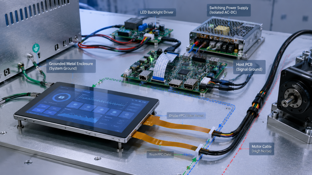
A capacitive touch sensor operates as part of the complete electrical system. Display signals, LED backlight drivers, switching power supplies, motors, chargers, cables, enclosure grounding, and nearby conductors can influence the signal environment.

Microchip’s design guidance describes tradeoffs among sensitivity, noise tolerance, water rejection, power consumption, and touch latency. It also notes that shielding can prevent unintended activation but can change sensor loading or sensitivity.[3]
The engineering review should include:
- Power-supply topology and ripple
- Backlight switching frequency and cable routing
- Display and touch FPC separation
- Ground reference between the touch controller and host
- Cover-glass and enclosure grounding structure
- Metal bezel or support locations near the sensor
- Charger, motor, relay, inverter, or radio operating states
- Production cable lengths and connector retention
- Touch-controller tuning used in the approved sample
Bench testing with a development power supply is not sufficient when the final product contains different power electronics, cables, motors, or enclosure materials. Repeat touch validation in the assembled equipment under representative operating states.
Translate Environmental Labels Into Testable Requirements
“Industrial touch,” “medical touch,” “outdoor touch,” and “automotive touch” do not define universal specifications. Each label must be translated into measurable conditions relevant to the finished equipment.
| Environment Area | Requirement to Define |
|---|---|
| 温度 | Operating and storage limits, startup condition, exposure duration, and acceptable display and touch behavior |
| Moisture | Droplets, condensation, cleaning, continuous exposure, operating state, sealing responsibility, and false-touch criteria |
| Gloves | Exact glove material and thickness, user action, required controls, and acceptance rate |
| Cleaning chemicals | Named chemicals, concentration, contact method, frequency, cover material, printing, coatings, adhesive, and edge protection |
| Mechanical loading | Impact, vibration, pressing force, mounting stress, enclosure deformation, and applicable acceptance criteria |
| Electrical immunity | Equipment-level test requirement, grounding, cables, power state, enclosure, and operating mode |
| Ambient light | Installation location, cover reflections, screen content, viewing direction, and required readability |
Do not claim IP ratings, chemical compatibility, automotive qualification, medical suitability, or compliance from the touch technology alone. Confirm the exact product configuration, test method, responsible party, report, and finished-equipment requirements.
Coordinate Two FPCs and the Mechanical Structure
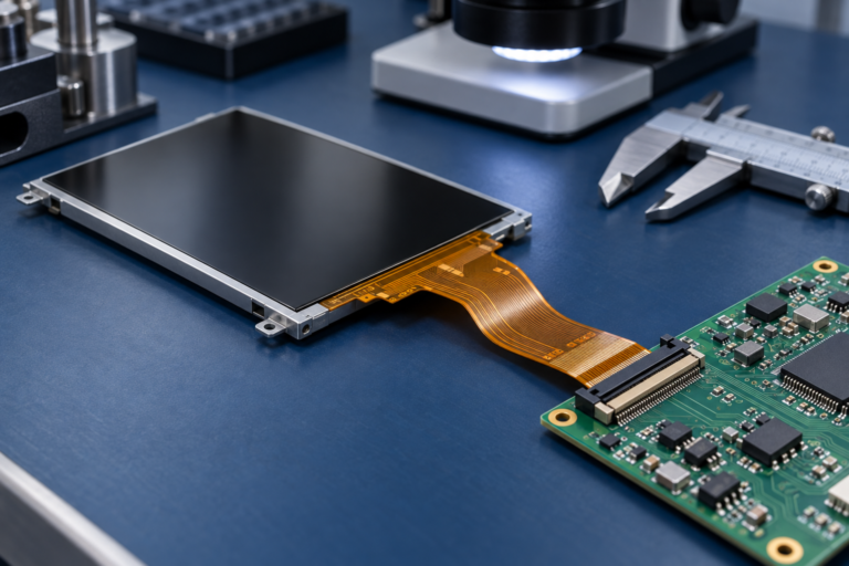
A touch display commonly has a display FPC and a separate touch FPC. Their positions, bend areas, connectors, stiffeners, shielding, and assembly sequence can determine whether the module fits the product.
| 機械項目 | レビュー質問 |
|---|---|
| LCD and touch alignment | Are the active areas and visible opening aligned within the complete tolerance stack? |
| FPC exits | Can both tails reach the PCB without crossing sharp edges, heat sources, fasteners, or moving parts? |
| コネクタアクセス | Can each connector be operated and inspected during assembly? |
| Cover-glass support | Does the enclosure support approved areas without loading the active LCD or touch sensor? |
| Adhesive and sealing | Are bonding width, compression, surface preparation, contamination control, and environmental responsibilities defined? |
| Metal structure | Could the bezel, brackets, screws, or ground elements affect capacitive sensing? |
| Service access | Can the display be removed without damaging the cover glass, FPC, connectors, or enclosure? |
Review the supplier drawing and enclosure CAD together. Do not design the display opening, PCB, and mounting structure from independent nominal dimensions.
Start With an Existing Touch Display Configuration
RJY Displayの現在の display module portfolio provides existing product paths for initial engineering review.[1] Product pages should be treated as candidate-discovery pages rather than automatic compatibility approvals.
When the core LCD platform is suitable, a project can evaluate surrounding changes such as:
- Touch sensor and controller coordination
- Cover-glass outline, printing, thickness, and surface requirements
- Display and touch FPC coordination
- 接着構造
- Backlight and dimming requirements
- Host interface or controller-board coordination
- Touch mapping, orientation, panel, or boot-related firmware configuration
- Mechanical structure and enclosure integration
This scope begins with an available LCD platform. It should not be interpreted as the ability to create any arbitrary LCD size, pixel matrix, or panel architecture from scratch.
For small embedded products, review the small touchscreen display guide. For the broader development process, see the カスタムTFT LCDディスプレイガイド.
Compare Candidate Touch Display Modules
| Decision Area | Candidate A | Candidate B | 必要な証拠 |
|---|---|---|---|
| LCDモデルおよびリビジョン | Record | Record | Current controlled datasheet and drawing |
| タッチ技術 | Record | Record | Touch specification and application requirement |
| Sensor and controller | Record | Record | Exact controller, firmware, sensor definition, and host interface |
| カバーガラス | Record | Record | Drawing, material, thickness, printing, and surface requirements |
| Bonding | Record | Record | Assembly definition and visual acceptance criteria |
| Touch behavior | Test | Test | Required contacts, tools, gloves, moisture, edges, and gestures |
| Host support | 確認 | 確認 | Driver, voltage, reset, interrupt, coordinate mapping, and OS image |
| 機械的適合性 | Evaluate | Evaluate | LCD, touch, lens, FPC, PCB, and enclosure drawings |
| Environmental fit | Evaluate | Evaluate | Defined application tests and configuration-specific evidence |
| Change control | 確認 | 確認 | Revision, substitution, firmware, PCN, and EOL procedures |
A lower-cost candidate should not pass the comparison when its controller, driver, cover structure, mechanical drawing, or environmental behavior remains undefined.
Validate the Complete Touch Display Sample
| 検証領域 | 最小限のレビュー |
|---|---|
| Display image | Native timing, full-screen patterns, orientation, startup, sleep, wake, repeated restart, and error states |
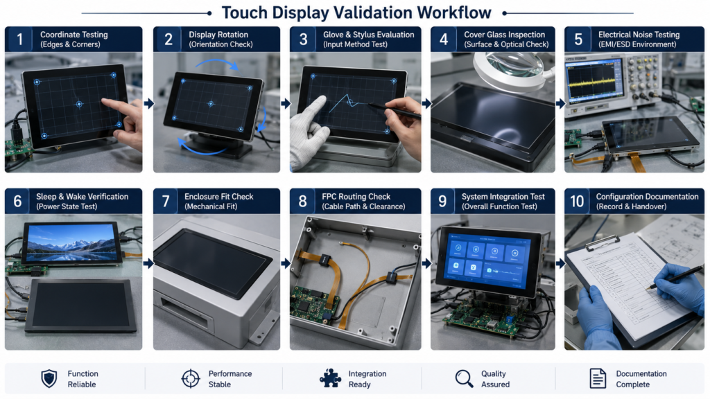
| Touch coordinates | Center, edges, corners, X/Y direction, rotation, scaling, multi-display association, and application targets |
| User input | Required fingers, stylus, gloves, gestures, contact count, pressure, and UI workflow |
| Cover and bonding | Appearance, sensitivity, alignment, bubbles, particles, border area, adhesives, and enclosure support |
| Electrical operation | Production power supply, backlight states, chargers, motors, radios, cables, grounding, and peripheral activity |
| 環境 | Defined temperature, moisture, cleaning, mechanical, and electrical-immunity conditions |
| ファームウェア | Controller version, host driver, orientation, sleep, wake, boot, update, and recovery behavior |
| 機械的組み立て | Fit, alignment, FPC routing, connector access, adhesive area, tolerance stack, and service procedure |
| Configuration record | LCD, sensor, controller, cover glass, FPC, board, firmware, cable, adhesive, enclosure, and open issues |
Record the approved hardware and software configuration rather than approving only a product name. Changing the LCD, touch controller, sensor, cover glass, adhesive, board revision, firmware, cable, or enclosure may require partial revalidation.

What to Send for a Touch Display Review
Provide the following information for a useful recommendation and quotation:
- 対象製品およびアプリケーション環境
- Required LCD active area, resolution, orientation, and module envelope
- Representative UI artwork and smallest touch targets
- Host MCU, application processor, control board, or video source
- Available display and touch interfaces
- Preferred touch technology or required input tools
- Number of simultaneous contacts and required gestures
- Cover-glass drawing, thickness, printing, and surface requirements
- Bonding and optical requirements
- Glove, moisture, cleaning, and electrical-noise conditions
- Display and touch FPC direction, connector position, and PCB constraints
- Operating system, driver, firmware, orientation, sleep, and wake requirements
- Mechanical drawing or available enclosure CAD
- Required validation conditions and documentation
- 試作品、パイロット、量産、および予想年間数量
- Existing display or touch datasheets when replacing another module
Request a Touch Display Compatibility Review
RJY Display can review an existing TFT LCD platform against your touch technology, controller, cover glass, bonding, interface, FPC, firmware, backlight, host-board, and mechanical requirements.
Browse current TFT LCD display modules, 、レビューする RJY Displayのカスタムソリューション範囲または send your host-board, UI, cover-glass, and enclosure requirements for engineering review.
よくあるご質問
What is a TFT LCD module with touch screen?
It is a coordinated display assembly containing a TFT LCD and a touch sensor, normally with a touch controller, FPC, cover structure, bonding or spacing arrangement, and separate electrical connections to the host. The exact included components must be confirmed for each module.
静電容量式タッチと抵抗膜式タッチのどちらを選ぶべきですか?
Choose from the required input tools, gestures, contact count, cover structure, user interface, environment, host support, and validation results. Projected capacitive and resistive touch use different sensing methods, and neither technology is universally correct for every product.
Does the touchscreen use the same interface as the TFT LCD?
Usually not. The LCD receives image data through a display interface, while the touch controller commonly uses a separate host connection such as I2C, USB, or SPI. Both interfaces, their power requirements, firmware, and connectors must be reviewed.
Can I add thicker custom cover glass without changing the touch design?
Not automatically. Greater distance between the user and a capacitive sensor can reduce sensitivity. The cover material, thickness, sensor geometry, controller firmware, bonding, enclosure, and required input behavior should be evaluated as one configuration.
Why are touch coordinates incorrect after rotating the display?
The display orientation and touch-coordinate transformation may not be using the same rotation, origin, axis direction, or scaling. Confirm the touch driver, operating-system configuration, display association, controller range, and application behavior for every supported orientation.
What information is needed for a touch display quotation?
Provide the application, LCD size and resolution, mechanical envelope, host board, display and touch interfaces, input tools, contact count, cover-glass drawing, bonding requirements, environment, FPC constraints, firmware needs, validation requirements, quantities, and available drawings or datasheets.
参考文献
- RJY Display, “Display Modules.” https://rjydisplay.com/display-modules/
- Texas Instruments, “TSC2007 Nano-Power Touch Screen Controller with I²C Serial Interface Datasheet.” https://www.ti.com/lit/ds/symlink/tsc2007.pdf
- Microchip Technology, “AN2934: Capacitive Touch Sensor Design Guide.” https://ww1.microchip.com/downloads/aemDocuments/documents/TXFG/ApplicationNotes/ApplicationNotes/Capacitive-Touch-Sensor-Design-Guide-DS00002934-B.pdf
- NXP Semiconductors, “AN12940: Use Case of RT1170 LCD Display System Based on MIPI DSI.” https://www.nxp.com/docs/en/application-note/AN12940.pdf
- Android Open Source Project, “Touch Devices.” https://source.android.com/docs/core/interaction/input/touch-devices
ディスプレイプロジェクトを計画中ですか?
ディスプレイサイズ、解像度、インターフェース、輝度、タッチ要件、コントローラーボード要件、およびアプリケーション環境を共有してください。.
どのディスプレイがプロジェクトに適しているかまだお決まりでないですか?
RJYのエンジニアリングチームにご相談いただき、ディスプレイマッチング、コントローラーボードの確認、およびカスタマイズについて話し合ってください。.