Facing a bottleneck in your Embedded Display Project?
Don’t let complex integration or supply chain issues slow your time-to-market. Book a free consultation with the RJY expert team for tailored design and manufacturing support.

An online water quality monitoring station can include sample handling, sensors, transmitters, analyzers, control electronics, communications hardware, a local operator interface, and a remote supervisory system. A TFT LCD can be an important part of that equipment, but it is not the sensor, the analytical method, or proof that the displayed result is correct.
For an OEM or system integrator, the display-selection question is not simply whether a screen can show values and trend lines. The display must support the operator workflow, match the actual host interface, fit the enclosure, work with the intended touch method, and remain understandable when the monitoring station is installed in its real operating environment.
This guide explains how to select a TFT LCD for an online water quality monitoring HMI while keeping the sensor layer, analyzer layer, local HMI, remote monitoring platform, and control functions clearly separated.
An online monitoring station commonly has several distinct functions. The sensor or sample-contact hardware obtains an input from the water or sample stream. The instrument electronics or analyzer processes that input according to the completed measurement design. The local HMI presents selected information and accepts permitted operator input. A remote SCADA system, supervisory workstation, or cloud-connected platform may present data at another location.
These functions may share one enclosure, but they should not be treated as interchangeable. A TFT LCD does not measure pH, turbidity, conductivity, dissolved oxygen, temperature, or another water quality parameter. A touchscreen does not establish calibration, measurement accuracy, sample integrity, alarm validity, or regulatory acceptance.
The U.S. Environmental Protection Agency describes online water quality monitoring as the use of online instruments for real-time measurement in source waters or distribution systems, with supporting monitoring-station and communications-system design considerations.1 The local HMI belongs to the operator-information layer within that broader system, rather than replacing the instrument or monitoring program.
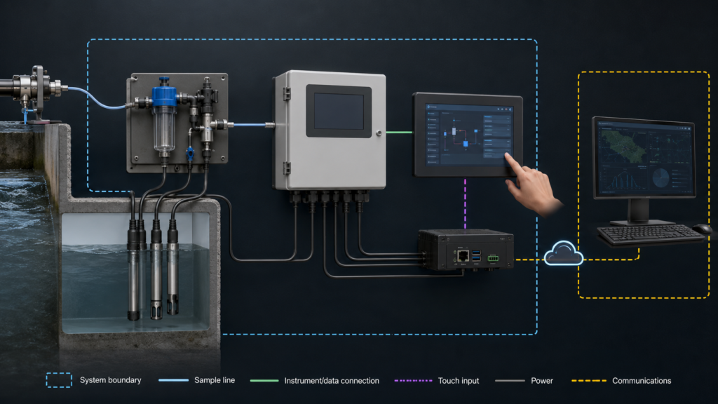
Defining these boundaries early prevents ambiguous requirements such as asking a display module to “support water quality measurement.” A useful requirement instead states what the operator must see, which actions may be requested, which device owns the measurement data, and what happens when information is unavailable or stale.
The display should be selected after the team understands the actual user workflow. A compact station may need current operating state, sample-path status, selected channels, communication state, maintenance prompts, alarms, and guided service steps. A larger analyzer panel may additionally need historical views, manual sampling prompts, configuration menus, calibration workflows, access levels, or multilingual screens.
Build representative pages with the expected content before deciding on panel size or resolution. Include the real number of channels, alarm conditions, navigation levels, font sizes, trend windows, status indicators, maintenance tasks, and user positions. This makes it easier to decide whether the equipment needs a compact local HMI, a larger panel-mounted display, a separate service display, or a remote interface in addition to the local HMI.
Do not equate sensor complexity with display complexity. EPA resources identify a wide variety of water-quality parameters and monitoring uses, but the local operator may only need a clearly prioritized subset of instrument and station information at a given time.2 The correct display is determined by the operator’s decision task, viewing distance, environmental conditions, and interface hierarchy.
A local TFT HMI and a remote supervisory display can serve different roles. The local HMI may be used at the enclosure for commissioning, routine checks, maintenance, controlled configuration, and fault recovery. A remote system may aggregate information from multiple stations, support operating-room visibility, store historical data, or provide access to authorized users away from the field location.
Do not assume that a local embedded display must reproduce every remote dashboard view. Conversely, do not assume that remote access removes the need for a usable local interface. The proper arrangement depends on the maintenance strategy, communications availability, required local tasks, power-up behavior, access-control approach, and completed monitoring-system architecture.
The display specification should therefore define which data are intended for local viewing, how the host handles communication loss, whether cached information can be shown, how stale data are identified, and which actions remain available when a remote connection is unavailable.
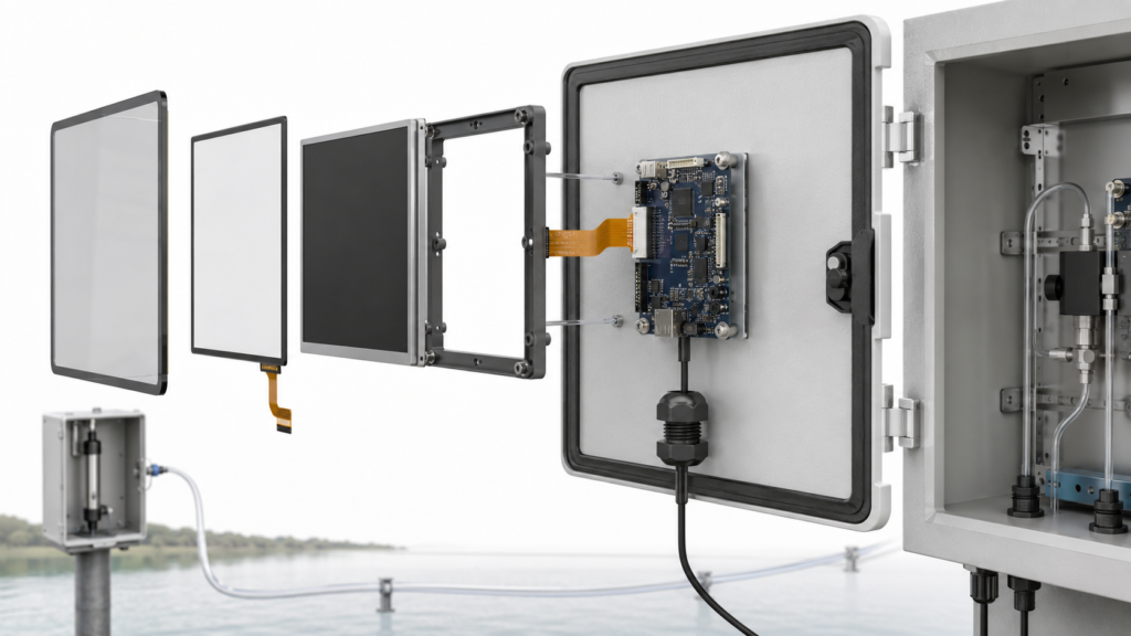
A raw TFT LCD module normally uses a native interface such as RGB, LVDS, MIPI DSI, or eDP. The selected HMI host must support the specific panel interface, timing, pixel format, power requirements, connector arrangement, initialization sequence, backlight control, software configuration, and display orientation.
A connector that appears compatible is not enough. Engineers should verify the module datasheet and host documentation together: pin assignment, voltage levels, panel timing, FPC routing, driver availability, startup sequence, backlight enable behavior, and touch-controller connection.
If the intended host offers HDMI but the selected TFT requires raw MIPI DSI, RGB, LVDS, or eDP, a passive cable cannot perform the conversion. The project requires a compatible active controller or bridge. That active device becomes part of the electrical, firmware, thermal, mechanical, startup, and lifecycle design.
Host software also matters. NXP’s LCD interface documentation, for example, describes a driver for a defined display-interface peripheral; it does not imply that every panel, processor, carrier board, cable, or operating-system image is mutually compatible.3
The touchscreen input path is separate from the TFT video path. A projected-capacitive touch sensor, resistive touch sensor, or other input method has its own controller, connection, firmware, grounding requirements, and software driver. The display interface drives pixels to the panel; the touch system reports user input to the host.
Touch selection should reflect the actual field workflow. Consider gloves, water or cleaning residues, target size, expected maintenance actions, cover-lens material, enclosure grounding, nearby electronics, and the consequences of unintended input. A generic claim that a panel “has capacitive touch” does not establish reliable operation in a specific outdoor or utility-site enclosure.
Where a task needs tactile feedback or a deliberately separated action, physical controls may be more appropriate. Their electrical and functional requirements should be evaluated independently from the TFT module and touch sensor.
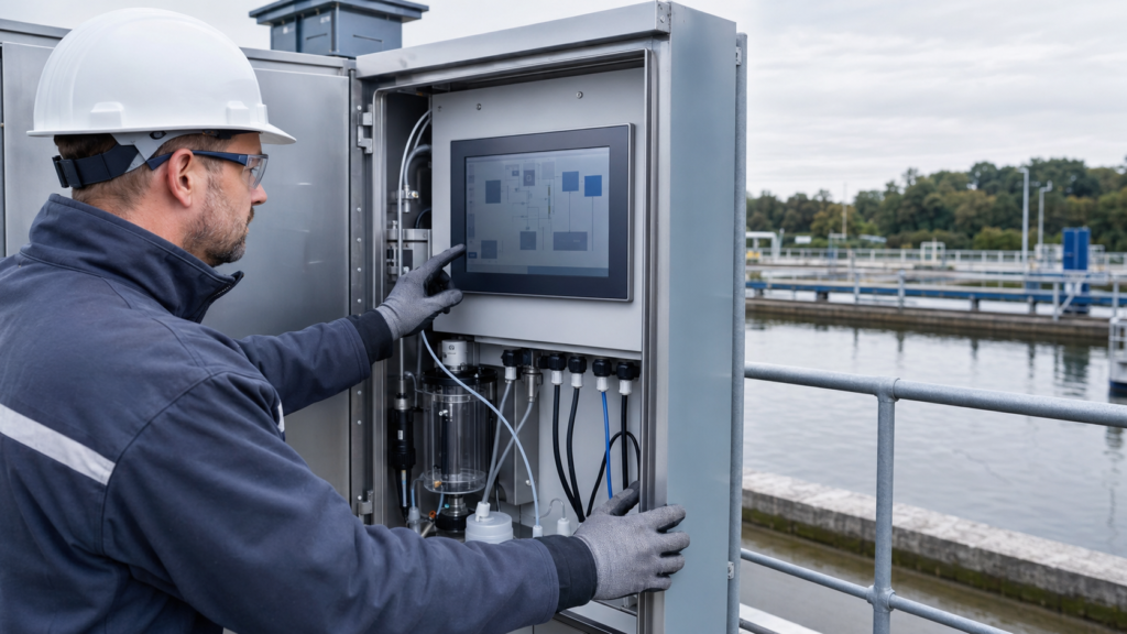
The finished HMI must work within the completed enclosure. Review the active area, viewing angle, front cover, cutout, mounting method, connector access, FPC bend requirements, cable routing, service approach, internal heat sources, condensation risk, expected lighting, and sample-system hardware around the display assembly.
Outdoor or semi-outdoor installations should be evaluated under representative lighting rather than only under desk conditions. Reflections, mounting angle, cover-lens treatment, operator position, and screen content all affect readability. The completed display stack should be assessed with the final enclosure materials rather than as a bare module.
The system’s environmental suitability, ingress protection, electrical design, communications resilience, and overall compliance are properties of the completed equipment. They are not established by selecting an LCD module alone.
An HMI should help the user understand whether the displayed information is current, unavailable, in maintenance, or awaiting system recovery. A value that remains on screen after a communication interruption or host restart can be misunderstood if the application does not present its status clearly.
Define the display behavior for instrument startup, sensor replacement, analyzer maintenance, local configuration, loss of remote communications, host restart, backlight initialization, and recovery after an expected interruption. The final equipment design should make clear which state is being shown and which user actions are permitted.
Do not use the TFT screen as evidence that an alarm decision or analytical result is valid. Alarm logic, data qualification, calibration handling, record retention, and operational response belong to the completed instrument and monitoring-system design.
Validation should use the intended display, touch stack, host board, enclosure, harness, sample-system configuration, application software, and representative operating conditions. The goal is to confirm that the operator interface functions as intended in context; it is not to infer sensor accuracy or water-quality performance from the display integration.
A project-specific plan can include representative screens, viewing positions, ambient lighting, expected touch conditions, display startup, communication interruption, local and remote state behavior, cable retention, service access, and recovery after power interruption. Write acceptance criteria before design freeze.
Terms such as “readable outdoors,” “glove operation,” or “real-time display” need defined conditions. State the intended lighting, content, glove type, target size, data-update context, and recovery behavior so the HMI requirement can be reviewed and tested meaningfully.
For an online water quality monitoring HMI review, provide the enclosure drawing, target active area, orientation, representative GUI, host processor or board, available native display interfaces, touch and cover requirements, lighting conditions, sample-system layout constraints, cable routing, power sequence, project stage, and estimated demand range.
RJY Display can review suitable existing display platforms and project-specific integration options around touch, cover lenses, backlight, interface, FPC, controller-board coordination, and mechanical fit. Feasibility depends on the confirmed module and requirements. It should not be interpreted as a commitment to create any arbitrary LCD cell size from zero or to qualify a complete monitoring instrument.
Request an online water quality monitoring HMI compatibility review with the display, host, interface, touch, optical, mechanical, and workflow information needed for a practical evaluation.
No. The TFT LCD presents information. Measurement depends on the sensor, analyzer or instrument electronics, sample handling, analytical method, calibration approach, and completed monitoring system.
No. A local HMI is used at the station for defined operator and service tasks. A remote system may aggregate information, store history, or support authorized users at another location. The two interfaces can complement each other but should be specified separately.
No. A passive cable cannot convert HDMI into a raw MIPI, RGB, LVDS, or eDP panel interface. A compatible active controller or bridge is required and must support both the source and the exact panel requirements.
No. Touch normally uses a separate sensor, controller, connection, firmware, and software path. The display interface drives pixels to the LCD, while the touch system reports user input to the host.
Provide the enclosure drawing, target active area, representative GUI, host platform, native display interface options, touch and cover requirements, lighting conditions, sample-system constraints, cable routing, power sequence, project stage, and expected demand range.
Share your display size, resolution, interface, brightness, touch requirement, controller board requirement, and application environment.
Continue reading related display technology guides and application references.
Talk to RJY’s engineering team for display matching, controller board review, and customization discussion.