Facing a bottleneck in your Embedded Display Project?
Don’t let complex integration or supply chain issues slow your time-to-market. Book a free consultation with the RJY expert team for tailored design and manufacturing support.

A discontinued TFT LCD can create a disproportionate problem for an otherwise stable product. The equipment may still be in production, installed in the field, or expected to remain serviceable for years, yet the original display module is no longer available through normal channels.
The quickest reaction is often to search for another LCD with the same diagonal size and resolution. That approach is rarely sufficient. A replacement must work with the existing enclosure, mounting structure, host board, power system, display interface, firmware, backlight circuit, touch controller, and user interface. A panel that looks equivalent in a catalog may still require a new cable, adapter board, firmware change, mechanical modification, or complete requalification.
The objective is therefore not to find a screen that merely resembles the discontinued model. It is to identify the lowest-risk replacement path that preserves as much of the existing product architecture as practical.
Before beginning a redesign, confirm the original module’s actual lifecycle status. “Unavailable from our current distributor” is not always the same as “no longer manufactured.” Inventory may have moved to another authorized channel, the model may have been replaced by a documented revision, or the supplier may still accept a final production order.
Lifecycle terminology varies among manufacturers. Texas Instruments, for example, distinguishes between products that are not recommended for new designs, products in a last-time-buy phase, and products that are fully obsolete.[1] This is an example of a structured lifecycle system, not a universal timetable for LCD suppliers.
Request written confirmation of:
A last-time buy can protect short-term production, but it does not remove the need for a qualified replacement. The remaining inventory may be insufficient for field service, future production, or unexpected demand.
The best replacement projects begin with a controlled technical baseline. If the original module is evaluated only after stock has been exhausted, the engineering team may discover that important drawings, firmware files, samples, and production records are missing.
Preserve at least one verified golden sample from a working production unit. Record the module label, revision, date code, connector orientation, cable assembly, mounting position, displayed image, backlight behavior, touch response, startup sequence, and operating conditions.
The documentation package should include:
If the original manufacturer documentation is incomplete, measurements from a functioning system may help establish a baseline. However, measurement should supplement—not replace—the original electrical and timing specifications whenever those documents remain available.
Diagonal size and resolution are only the beginning of equivalency. The replacement must be reviewed across several engineering domains.
| Compatibility Area | Items to Compare | Risk if Overlooked |
|---|---|---|
| Optical | Resolution, brightness, contrast, viewing direction, color behavior, active area, polarizer | The screen works but no longer meets readability or UI requirements |
| Mechanical | Outline, thickness, active-area position, bezel, mounting points, FPC exit, connector location | The module cannot be assembled into the existing enclosure |
| Electrical | Logic voltage, current, bias rails, reset, enable, sequencing, grounding | No image, unstable operation, or component damage |
| Interface and timing | Interface type, lane or channel count, pixel clock, blanking, polarity, pixel format, initialization | The host cannot drive the panel correctly |
| Backlight | LED configuration, forward voltage, current, PWM, enable polarity, thermal load | Incorrect brightness, driver overload, flicker, or overheating |
| Touch | Touch type, controller, communication interface, firmware, coordinate mapping, cover structure | Video works but touch is unavailable or misaligned |
| Software and firmware | Panel driver, initialization commands, orientation, startup behavior, controller-board configuration | Blank screen, incorrect colors, wrong orientation, or boot-time failure |
| Lifecycle and production | Supplier status, revision control, expected demand, documentation, change notification, validation samples | The replacement creates another supply problem shortly after qualification |
This system view explains why two modules with identical size and resolution may not be interchangeable. The display is an electrical, optical, mechanical, and software-dependent subsystem.
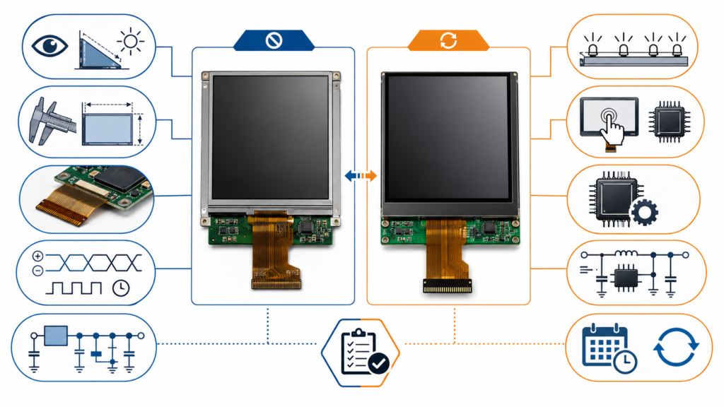
“Form, fit, and function” is useful shorthand, but each category needs a display-specific definition.
Form includes the outer dimensions, glass and frame outline, module thickness, active-area position, bezel width, mounting method, FPC direction, connector position, touch-panel outline, and cover-glass geometry. Even a small difference can affect screw locations, enclosure pressure, sealing, cable routing, or the visible alignment between the LCD and front window.
Fit includes more than the connector mating physically. The pin assignment, contact orientation, logic voltage, power rails, backlight circuit, display interface, signal polarity, grounding, and timing must be compatible with the host system.
A connector with the same pin count can carry a completely different pin definition. Connecting an unverified module can place a supply voltage on a signal pin or reverse the location of differential pairs.
Function includes image stability, color order, brightness, viewing behavior, refresh performance, startup time, touch response, orientation, dimming, sleep behavior, and operation across the product’s intended environment.
A replacement has not been qualified merely because it displays a test image on the bench. It must satisfy the functions that matter in the actual equipment.
The lowest-risk path depends on available inventory, the remaining product lifetime, annual demand, technical differences, and the amount of redesign the OEM can accept.
| Replacement Path | Best Use | Main Advantage | Main Limitation |
|---|---|---|---|
| Verified remaining stock | Short remaining production or service demand | No immediate redesign | Finite inventory, storage, traceability, and counterfeit risk |
| Manufacturer-designated successor | A documented next-generation module exists | May preserve part of the original design intent | Successor does not automatically mean drop-in compatible |
| Compatible catalog module | A current module closely matches the original | Lower development effort than deeper customization | May still require cable, firmware, backlight, or mechanical changes |
| Semi-custom module based on an existing platform | The available module is close but needs FPC, backlight, touch, cover glass, interface, or structural changes | Can preserve more of the existing product without creating a new LCD size from zero | Requires engineering review, development cost, MOQ, and validation |
| Controller or adapter-board solution | The new panel interface or timing cannot be driven directly by the existing host | May preserve the main host board and software architecture | Adds space, power, firmware, signal-integrity, and supply considerations |
If none of these paths can meet the product requirements safely, a broader redesign may be more responsible than forcing an unsuitable panel into the old architecture.
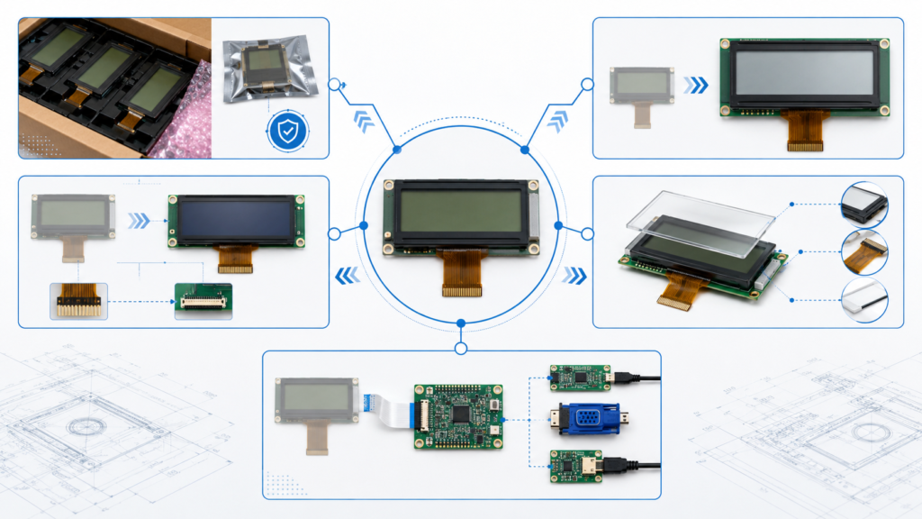
A semi-custom solution is often useful when a current display platform is technically close to the discontinued module but does not fit every system requirement.
Practical modification areas may include:
This approach should not be described as creating any arbitrary new LCD size from scratch. The practical starting point is an existing display module whose core optical and electrical characteristics are sufficiently close to the original requirement.
For an overview of module-level modification options, see Custom TFT LCD Displays: A Complete Guide for OEM Product Development.
A controller or adapter board may help when the replacement display uses a different interface, requires different timing, or cannot be connected directly to the legacy host board.
For example, an existing system output may need to be converted for a panel using LVDS, MIPI DSI, eDP, HDMI, or another interface. The controller path must still be qualified for resolution, timing, pixel format, power, backlight, touch, firmware, and operating-system behavior.
MIPI DSI illustrates why the interface name alone is insufficient. MIPI defines DSI as a high-speed interface between a host processor and a display module, while its operation may involve D-PHY configuration, display commands, and panel-specific requirements.[2] NXP’s DSI documentation also distinguishes video and command modes and shows that lane configuration, timing, power, reset, and backlight control are part of panel bring-up.[3]
A controller-board solution can reduce changes to the main product only when the additional board itself can be accommodated. Review:
RJY Display’s LCD interface guide provides additional background on common display interfaces.
RGB panels may expose many parallel data and timing signals. The replacement must match the supported color depth, pixel clock, synchronization behavior, data-enable logic, voltage level, and pin mapping. A similar resolution does not guarantee identical timing.
For LVDS, check single- or dual-channel configuration, bit mapping, color depth, pixel clock, connector assignment, polarity, and panel power. Different LVDS mapping conventions can produce incorrect colors even when an image appears.
MIPI DSI replacements require review of lane count, lane rate, video or command mode, pixel format, initialization commands, D-PHY timing, reset behavior, power sequence, and connector mapping. The panel’s driver IC and initialization data can be as important as its resolution.
For eDP, review lane count, link rate, panel power, auxiliary-channel behavior, backlight control, timing, connector definition, and host compatibility. A laptop-style connector appearance does not establish equivalency.
Smaller SPI or MCU-connected displays may depend heavily on the controller IC, command set, initialization sequence, library, frame-buffer strategy, and host software. A replacement using another controller IC can create a larger software change than expected.
Separate fixed constraints from negotiable preferences. The enclosure opening, host interface, available power, UI resolution, touch method, and operating environment may be fixed. Brightness, cover-glass detail, cable construction, or mounting brackets may offer more flexibility.
Use the original specification package to eliminate candidates with obvious mechanical, electrical, interface, or lifecycle conflicts. Do not request samples solely because the catalog title looks similar.
Compare the original and candidate module line by line. Mark each parameter as identical, compatible with verification, adaptable, or incompatible. This makes the real development scope visible before tooling or sample costs are committed.
Decide whether the gaps can be resolved through an FPC, cable, controller board, backlight circuit, touch configuration, cover glass, firmware, mechanical bracket, or another module-level change.
Test the candidate in the actual product architecture. A generic evaluation board may confirm basic panel operation, but it does not prove compatibility with the production host, power supply, enclosure, cable, touch system, or software.
The validation plan should reflect the equipment’s real requirements and any standards that apply to the finished product. Depending on the application, this may include functional operation, startup behavior, thermal testing, brightness and visual inspection, touch performance, signal stability, power cycling, mechanical fit, and environmental evaluation.
Once approved, document the new part number, drawings, firmware, cable, assembly instructions, inspection criteria, approved sample, revision level, and effective production date. Do not allow the replacement to enter production as an undocumented purchasing substitution.
| Validation Stage | Example Checks | Approval Evidence |
|---|---|---|
| Documentation review | Datasheet, drawing, pinout, timing, interface, lifecycle | Completed comparison matrix |
| Bench bring-up | Power, reset, image, backlight, touch, dimming | Stable operation with recorded configuration |
| Mechanical integration | Outline, active-area alignment, FPC routing, mounting stress | Approved assembly sample and drawing |
| System function | Boot, sleep, wake, orientation, UI, touch mapping | Product-level functional test result |
| Application validation | Temperature, operating duration, power cycling, readability, environmental requirements | Approved validation report based on product requirements |
| Production control | Revision, inspection, firmware, approved vendor and traceability | Released BOM and change record |
A complete RFQ allows the supplier to evaluate the real adaptation scope rather than quote an unrelated display with a similar headline specification.
Prepare:
If important documentation is unavailable, state this clearly. The project may require additional reverse engineering or measurement, and compatibility may not be confirmable from photographs alone.
Obsolescence management should continue after the replacement is released. IEC 62402:2019 describes obsolescence management as a lifecycle process that includes policy, planning, risk reduction, resolution selection, implementation, and performance improvement.[4]
For display-dependent products, practical measures include maintaining accurate approved-part records, archiving firmware and panel documentation, preserving a golden sample, monitoring supplier change notices, recording acceptable alternates, and reviewing lifecycle risk before a product enters long-term production.
Some electronic-component suppliers publish formal product-change and discontinuance processes. For example, TI describes lifecycle states and a withdrawal process with last-order and final-delivery periods.[5] Those dates should not be generalized to every LCD supplier, but they illustrate why documented notification channels matter.
The article What Is the Lifespan of a TFT LCD? explains why physical operating life and long-term availability should be evaluated separately.
RJY Display supports engineering review for TFT LCD modules, controller boards, and display customization based on existing module platforms. For a discontinued-display project, the practical direction may involve selecting a current module, comparing the electrical and mechanical differences, and coordinating relevant changes around the display.
Depending on project feasibility, the discussion may include cover glass, backlight, touch panel, interface, FPC, controller board, firmware, and mechanical structure coordination. This does not mean that every discontinued LCD can be reproduced exactly or that an entirely new panel size can be developed economically from scratch.
The goal is to identify a technically supportable replacement path with a defined validation scope.
Send RJY Display the original LCD part number, datasheet, pin definition, photographs, host-interface information, operating environment, annual demand, and target timeline. The engineering review can compare available TFT LCD modules and determine whether a standard module, semi-custom display, cable, controller board, firmware adaptation, or broader redesign should be evaluated.
Explore current display modules, review custom display support, or send your replacement requirements to RJY Display.
Not automatically. The replacement must also match or be adapted for the mechanical outline, active area, connector, pin definition, voltage, interface, timing, backlight, touch system, firmware, and operating environment.
The most important requirement is compatibility with the complete product system. No single specification confirms equivalency; the mechanical, electrical, optical, interface, software, touch, and lifecycle requirements must be reviewed together.
Sometimes. A controller or adapter board may convert the existing host output for a new panel, but the solution must still be checked for space, power, timing, firmware, backlight, touch, signal integrity, and long-term availability.
Not always. The more practical approach is often to start with an existing LCD platform and customize relevant surrounding elements such as the FPC, backlight, touch panel, cover glass, interface, controller board, firmware, or mechanical structure.
Provide the original part number, datasheet, drawing, pin definition, timing, interface, power and backlight data, touch information, host-board details, photographs, working sample if available, operating environment, annual demand, and project timeline.
Only after reviewing forecast demand, field-service requirements, storage conditions, traceability, authenticity, cash exposure, and the time needed to qualify a replacement. A last-time buy can provide temporary coverage, but it is not a substitute for a replacement strategy.
Share your display size, resolution, interface, brightness, touch requirement, controller board requirement, and application environment.
Continue reading related display technology guides and application references.
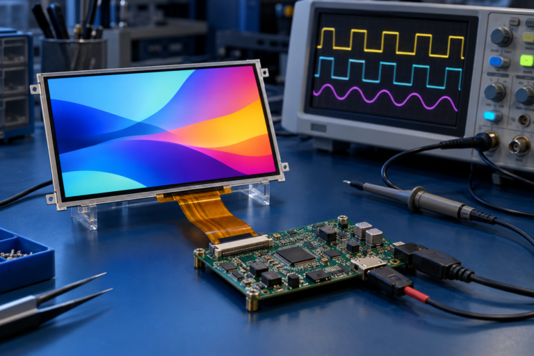
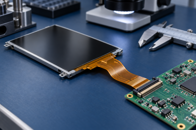
Talk to RJY’s engineering team for display matching, controller board review, and customization discussion.









