Incontri un collo di bottiglia nel tuo progetto di display embedded?
Non lasciare che integrazioni complesse o problemi di supply chain rallentino il tuo time-to-market. Prenota una consulenza gratuita con il team di esperti RJY per un supporto su misura in progettazione e produzione.
Come Sostituire un Modulo TFT LCD Fuori Produzione Senza Riprogettare l'Intero Prodotto
Pubblicato:
13 minuti di lettura
Aggiornato:
Un TFT LCD discontinuato può creare un problema sproporzionato per un prodotto altrimenti stabile. L'apparecchiatura può essere ancora in produzione, installata sul campo, o prevista per rimanere operativa per anni, ma il modulo display originale non è più disponibile attraverso i canali normali.
La reazione più rapida è spesso quella di cercare un altro LCD con la stessa dimensione diagonale e risoluzione. Tale approccio raramente è sufficiente. Una sostituzione deve funzionare con l'involucro esistente, la struttura di montaggio, la scheda host, il sistema di alimentazione, l'interfaccia display, il firmware, il circuito della retroilluminazione, il controller touch e l'interfaccia utente. Un pannello che appare equivalente in un catalogo può comunque richiedere un nuovo cavo, una scheda adattatrice, una modifica al firmware, una modifica meccanica o una completa riqualificazione.
L'obiettivo non è quindi trovare uno schermo che semplicemente assomigli al modello discontinuato. È identificare il percorso di sostituzione a minor rischio che preservi quanto più possibile l'architettura del prodotto esistente.
Prima di tutto, confermare cosa significa “Discontinuato”
Prima di iniziare una riprogettazione, confermare lo stato effettivo del ciclo di vita del modulo originale. “Non disponibile dal nostro distributore attuale” non è sempre la stessa cosa di “non più prodotto”. L'inventario potrebbe essere stato trasferito a un altro canale autorizzato, il modello potrebbe essere stato sostituito da una revisione documentata, oppure il fornitore potrebbe ancora accettare un ordine di produzione finale.
La terminologia del ciclo di vita varia tra i produttori. Texas Instruments, ad esempio, distingue tra prodotti non raccomandati per nuovi progetti, prodotti in fase di ultimo acquisto e prodotti completamente obsoleti.[1] Questo è un esempio di un sistema di ciclo di vita strutturato, non una tabella temporale universale per i fornitori di LCD.
Richiedere conferma scritta di:
Il numero di parte esatto del produttore e la revisione
Se il prodotto è attivo, limitato, in fase di ultimo acquisto o obsoleto
Le date di ultimo ordine e ultima spedizione, se applicabili
Eventuale successore raccomandato dal produttore
Se è cambiato solo un componente o se l'intero modulo è stato discontinuato
Inventario tracciabile rimanente e la sua storia di stoccaggio
Un ultimo acquisto può proteggere la produzione a breve termine, ma non elimina la necessità di una sostituzione qualificata. L'inventario rimanente potrebbe essere insufficiente per l'assistenza sul campo, la produzione futura o una domanda imprevista.
Preservare la baseline di visualizzazione originale prima della ricerca
I migliori progetti di sostituzione iniziano con una baseline tecnica controllata. Se il modulo originale viene valutato solo dopo che le scorte sono esaurite, il team di ingegneria potrebbe scoprire che disegni importanti, file firmware, campioni e registrazioni di produzione sono mancanti.
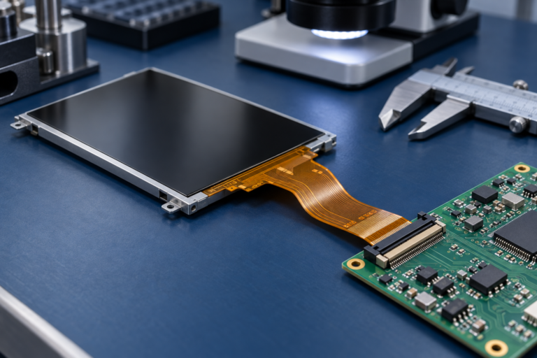
Preservare almeno un campione dorato verificato da un'unità di produzione funzionante. Registrare l'etichetta del modulo, la revisione, il codice data, l'orientamento del connettore, il gruppo cavi, la posizione di montaggio, l'immagine visualizzata, il comportamento della retroilluminazione, la risposta touch, la sequenza di avvio e le condizioni operative.
Il pacchetto di documentazione dovrebbe includere:
Datasheet originale del modulo LCD e disegno dimensionale
Definizione dei pin FPC o connettore
Tabella dei tempi di visualizzazione
Informazioni su interfaccia e formato pixel
Requisiti di alimentazione e sequenziamento di accensione
Informazioni su tensione, corrente, abilitazione e dimming della retroilluminazione
Documentazione del pannello touch e del controller touch
Pagine dello schema della scheda host relative al display
Codice di inizializzazione del display, driver, dati device-tree o firmware della scheda controller
Campione di produzione approvato e criteri di ispezione in ingresso
Se la documentazione originale del produttore è incompleta, le misurazioni da un sistema funzionante possono aiutare a stabilire una baseline. Tuttavia, la misurazione dovrebbe integrare—non sostituire—le specifiche elettriche e di temporizzazione originali quando tali documenti rimangono disponibili.
Un LCD sostitutivo è una corrispondenza a livello di sistema
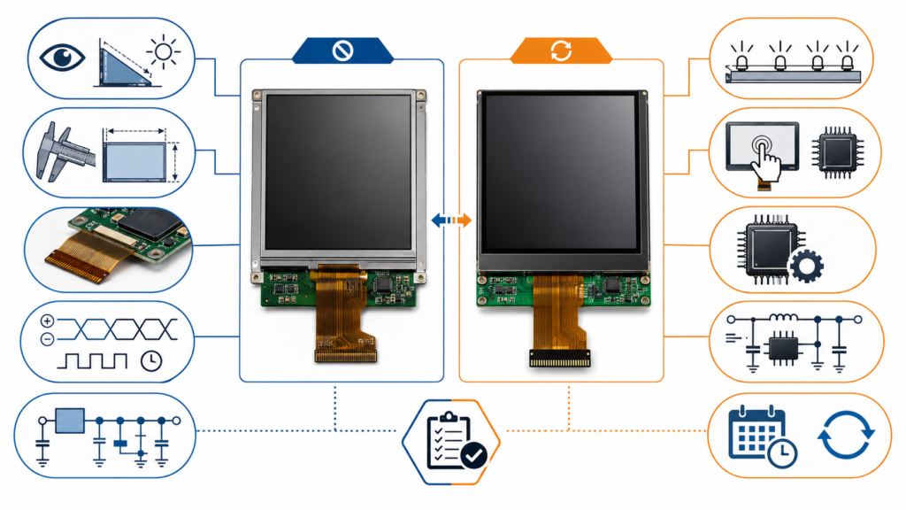
La dimensione diagonale e la risoluzione sono solo l'inizio dell'equivalenza. La sostituzione deve essere valutata in diversi ambiti ingegneristici.
Area di compatibilità
Elementi da confrontare
Rischio se trascurato
Ottico
Risoluzione, luminosità, contrasto, direzione di visualizzazione, comportamento colore, area attiva, polarizzatore
Lo schermo funziona ma non soddisfa più i requisiti di leggibilità o UI
graffio
Contorno, spessore, posizione dell'area attiva, cornice, punti di montaggio, uscita FPC, posizione del connettore
Il modulo non può essere assemblato nell'involucro esistente
Elettrico
Tensione logica, corrente, rail di polarizzazione, reset, abilitazione, sequenziamento, messa a terra
Nessuna immagine, funzionamento instabile o danni ai componenti
Interfaccia e temporizzazione
Tipo di interfaccia, numero di lane o canali, clock pixel, blanking, polarità, formato pixel, inizializzazione
Luminosità errata, sovraccarico del driver, sfarfallio o surriscaldamento
Toccare
Tipo touch, controller, interfaccia di comunicazione, firmware, mappatura coordinate, struttura del coperchio
Il video funziona ma il touch non è disponibile o è disallineato
Software e firmware
Driver del pannello, comandi di inizializzazione, orientamento, comportamento di avvio, configurazione della scheda controller
Schermo nero, colori errati, orientamento sbagliato o guasto all'avvio
Ciclo di vita e produzione
Stato del fornitore, controllo delle revisioni, domanda prevista, documentazione, notifica di modifiche, campioni di validazione
La sostituzione crea un altro problema di approvvigionamento poco dopo la qualificazione
Questa visione di sistema spiega perché due moduli con dimensioni e risoluzione identiche potrebbero non essere intercambiabili. Il display è un sottosistema dipendente da aspetti elettrici, ottici, meccanici e software.
Fattori di compatibilità per la selezione di un sostituto di TFT LCD fuori produzione
Cosa significano forma, adattamento e funzione per una sostituzione LCD
“Forma, adattamento e funzione” è una sintesi utile, ma ogni categoria necessita di una definizione specifica per i display.
Forma: Il modulo può occupare lo stesso spazio fisico?
La forma include le dimensioni esterne, il profilo del vetro e della cornice, lo spessore del modulo, la posizione dell'area attiva, la larghezza della cornice, il metodo di montaggio, la direzione del FPC, la posizione del connettore, il profilo del pannello touch e la geometria del vetro di copertura. Anche una piccola differenza può influire sulle posizioni delle viti, sulla pressione dell'involucro, sulla tenuta, sul percorso dei cavi o sull'allineamento visibile tra LCD e finestra frontale.
Adattamento: Può collegarsi al prodotto esistente?
L'adattamento include più del semplice accoppiamento fisico del connettore. L'assegnazione dei pin, l'orientamento dei contatti, la tensione logica, le linee di alimentazione, il circuito della retroilluminazione, l'interfaccia del display, la polarità del segnale, la messa a terra e la temporizzazione devono essere compatibili con il sistema host.
Un connettore con lo stesso numero di pin può avere una definizione dei pin completamente diversa. Il collegamento di un modulo non verificato può applicare una tensione di alimentazione su un pin di segnale o invertire la posizione delle coppie differenziali.
Funzione: Il prodotto finale si comporta come previsto?
La funzione include la stabilità dell'immagine, l'ordine dei colori, la luminosità, il comportamento di visualizzazione, le prestazioni di aggiornamento, il tempo di avvio, la risposta al tocco, l'orientamento, la regolazione della luminosità, il comportamento in sospensione e il funzionamento nell'ambiente previsto del prodotto.
Un sostituto non è qualificato semplicemente perché visualizza un'immagine di prova sul banco. Deve soddisfare le funzioni che contano nell'apparecchiatura reale.
Cinque percorsi pratici di sostituzione
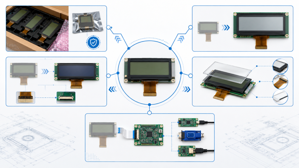
Il percorso a minor rischio dipende dall'inventario disponibile, dalla vita residua del prodotto, dalla domanda annuale, dalle differenze tecniche e dalla quantità di riprogettazione che l'OEM può accettare.
Percorso di sostituzione
Utilizzo ottimale
Vantaggio principale
Limitazione principale
Scorte rimanenti verificate
Breve domanda residua di produzione o assistenza
Nessuna riprogettazione immediata
Inventario limitato, stoccaggio, tracciabilità e rischio di contraffazione
Successore designato dal produttore
Esiste un modulo di nuova generazione documentato
Può preservare parte dell'intento progettuale originale
Il successore non significa automaticamente compatibile drop-in
Modulo di catalogo compatibile
Un modulo attuale corrisponde strettamente all'originale
Minore sforzo di sviluppo rispetto a una personalizzazione più profonda
Potrebbe richiedere comunque modifiche a cavi, firmware, retroilluminazione o meccanica
Modulo semi-personalizzato basato su una piattaforma esistente
Il modulo disponibile è vicino ma necessita di modifiche a FPC, retroilluminazione, touch, vetro di copertura, interfaccia o struttura
Può preservare più del prodotto esistente senza creare una nuova dimensione LCD da zero
Richiede revisione ingegneristica, costi di sviluppo, MOQ e validazione
Soluzione con controller o scheda adattatrice
La nuova interfaccia o temporizzazione del pannello non può essere pilotata direttamente dall'host esistente
Può preservare la scheda host principale e l'architettura software
Aggiunge considerazioni su spazio, alimentazione, firmware, integrità del segnale e approvvigionamento
Se nessuno di questi percorsi può soddisfare in modo sicuro i requisiti del prodotto, una riprogettazione più ampia potrebbe essere più responsabile che forzare un pannello inadatto nella vecchia architettura.
Percorsi di sostituzione per un modulo TFT LCD industriale obsoleto
Quando un display semi-personalizzato è la scelta migliore
Una soluzione semi-personalizzata è spesso utile quando una piattaforma display attuale è tecnicamente vicina al modulo fuori produzione ma non soddisfa ogni requisito di sistema.
Le aree di modifica pratica possono includere:
Lunghezza, direzione o disposizione dei pin del FPC
Posizione del connettore
Configurazione della retroilluminazione o obiettivo di luminosità
Integrazione touch capacitivo o resistivo
Profilo del vetro di copertura e coordinamento con il pannello frontale
Coordinamento dell'interfaccia o della scheda controller
Adattamento del firmware
Struttura meccanica attorno al modulo esistente
Questo approccio non deve essere descritto come la creazione di una nuova dimensione LCD arbitraria da zero. Il punto di partenza pratico è un modulo display esistente le cui caratteristiche ottiche ed elettriche principali siano sufficientemente vicine al requisito originale.
Quando una scheda controller può ridurre la riprogettazione
Una scheda controller o adattatrice può essere utile quando il display sostitutivo utilizza un'interfaccia diversa, richiede temporizzazioni differenti o non può essere collegato direttamente alla scheda host legacy.
Ad esempio, un'uscita di sistema esistente potrebbe dover essere convertita per un pannello che utilizza LVDS, MIPI DSI, eDP, HDMI o un'altra interfaccia. Il percorso del controller deve comunque essere qualificato per risoluzione, temporizzazione, formato pixel, alimentazione, retroilluminazione, touch, firmware e comportamento del sistema operativo.
MIPI DSI illustra perché il solo nome dell'interfaccia non è sufficiente. MIPI definisce DSI come un'interfaccia ad alta velocità tra un processore host e un modulo display, mentre il suo funzionamento può coinvolgere la configurazione D-PHY, i comandi di visualizzazione e requisiti specifici del pannello.[2] La documentazione DSI di NXP distingue inoltre le modalità video e comando e mostra che la configurazione delle lane, la temporizzazione, l'alimentazione, il reset e il controllo della retroilluminazione fanno parte del bring-up del pannello.[3]
Una soluzione con scheda controller può ridurre le modifiche al prodotto principale solo quando la scheda aggiuntiva stessa può essere allocata. Verificare:
Spazio disponibile per PCB e involucro
Compatibilità delle interfacce di ingresso e uscita
Consumo energetico ed effetto termico
Comportamento di avvio e riattivazione
Proprietà del firmware e processo di aggiornamento
Integrazione di retroilluminazione e touch
Lunghezza dei cavi e integrità del segnale
Disponibilità a lungo termine della scheda controller
RJY Display's guida all'interfaccia LCD fornisce ulteriori informazioni di base sulle interfacce display comuni.
Rischi di sostituzione specifici per interfaccia
Pannelli RGB o TTL
I pannelli RGB possono esporre molti segnali paralleli di dati e temporizzazione. Il ricambio deve corrispondere alla profondità di colore supportata, al clock dei pixel, al comportamento di sincronizzazione, alla logica di abilitazione dati, al livello di tensione e alla mappatura dei pin. Una risoluzione simile non garantisce una temporizzazione identica.
Pannelli LVDS
Per LVDS, verificare la configurazione a canale singolo o doppio, la mappatura dei bit, la profondità di colore, il clock dei pixel, l'assegnazione dei connettori, la polarità e l'alimentazione del pannello. Convenzioni di mappatura LVDS diverse possono produrre colori errati anche quando l'immagine appare.
Pannelli MIPI DSI
I ricambi MIPI DSI richiedono la verifica del numero di linee dati (lane), della velocità delle linee, della modalità video o comando, del formato pixel, dei comandi di inizializzazione, della temporizzazione D-PHY, del comportamento di reset, della sequenza di alimentazione e della mappatura dei connettori. Il circuito integrato di pilotaggio del pannello e i dati di inizializzazione possono essere importanti quanto la risoluzione.
Pannelli eDP
Per eDP, verificare il numero di linee dati, la velocità del collegamento, l'alimentazione del pannello, il comportamento del canale ausiliario, il controllo della retroilluminazione, la temporizzazione, la definizione del connettore e la compatibilità con l'host. L'aspetto di un connettore in stile laptop non stabilisce l'equivalenza.
Pannelli SPI e MCU
I display più piccoli con connessione SPI o MCU possono dipendere fortemente dal circuito integrato di controllo, dal set di comandi, dalla sequenza di inizializzazione, dalla libreria, dalla strategia del frame buffer e dal software host. Un ricambio che utilizza un diverso circuito integrato di controllo può richiedere una modifica software più ampia del previsto.
Un processo di qualificazione strutturato
1. Definire i Requisiti Non Negoziabili
Separare i vincoli fissi dalle preferenze negoziabili. L'apertura dell'involucro, l'interfaccia host, l'alimentazione disponibile, la risoluzione dell'interfaccia utente, il metodo di touch e l'ambiente operativo possono essere fissi. Luminosità, dettagli del vetro di copertura, costruzione del cavo o staffe di montaggio possono offrire maggiore flessibilità.
2. Selezionare i Moduli Candidati
Utilizzare il pacchetto di specifiche originale per eliminare i candidati con evidenti conflitti meccanici, elettrici, di interfaccia o di ciclo di vita. Non richiedere campioni solo perché il titolo del catalogo sembra simile.
3. Creare una Matrice delle Differenze
Confrontare il modulo originale e quello candidato riga per riga. Contrassegnare ciascun parametro come identico, compatibile con verifica, adattabile o incompatibile. Ciò rende visibile il reale ambito di sviluppo prima di impegnare costi per attrezzature o campioni.
4. Selezionare la Strategia di Adattamento
Decidere se le lacune possono essere risolte tramite un FPC, un cavo, una scheda di controllo, un circuito di retroilluminazione, una configurazione touch, un vetro di copertura, un firmware, una staffa meccanica o un'altra modifica a livello di modulo.
5. Testare i Campioni di Ingegneria
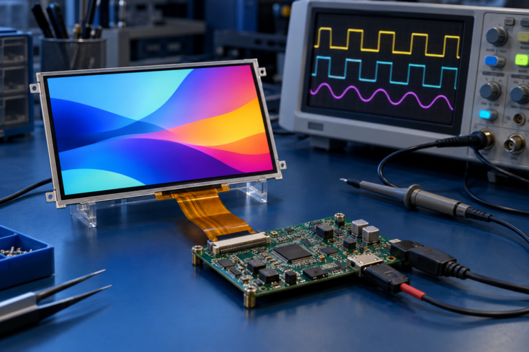
Testare il candidato nell'architettura di prodotto effettiva. Una scheda di valutazione generica può confermare il funzionamento di base del pannello, ma non prova la compatibilità con l'host di produzione, l'alimentatore, l'involucro, il cavo, il sistema touch o il software.
6. Eseguire la Validazione Appropriata all'Applicazione
Il piano di validazione deve riflettere i requisiti reali dell'apparecchiatura e gli eventuali standard applicabili al prodotto finito. A seconda dell'applicazione, ciò può includere funzionamento funzionale, comportamento all'avvio, test termici, luminosità e ispezione visiva, prestazioni touch, stabilità del segnale, cicli di alimentazione, adattamento meccanico e valutazione ambientale.
7. Controllare la Modifica di Produzione
Una volta approvato, documentare il nuovo numero di parte, i disegni, il firmware, il cavo, le istruzioni di assemblaggio, i criteri di ispezione, il campione approvato, il livello di revisione e la data di entrata in produzione effettiva. Non consentire che il ricambio entri in produzione come sostituzione di acquisto non documentata.
Matrice di validazione della sostituzione
Fase di Validazione
Esempi di Verifiche
Evidenza di Approvazione
Revisione della documentazione
Scheda tecnica, disegno, pinout, temporizzazione, interfaccia, ciclo di vita
Risultato del test funzionale a livello di prodotto
Validazione applicativa
Temperatura, durata operativa, cicli di alimentazione, leggibilità, requisiti ambientali
Rapporto di validazione approvato basato sui requisiti di prodotto
Controllo di produzione
Revisione, ispezione, firmware, fornitore approvato e tracciabilità
BOM rilasciato e registro delle modifiche
Cosa inviare quando si richiede una revisione della sostituzione
Una richiesta di preventivo completa consente al fornitore di valutare il reale ambito di adattamento anziché quotare un display non correlato con una specifica principale simile.
Preparare:
Produttore LCD originale e numero di parte completo
Scheda tecnica, disegno e definizione dei pin FPC
Fotografie chiare del modulo e del connettore
Un campione funzionante, se disponibile
Dimensioni del display, risoluzione, area attiva e requisito di luminosità
Informazioni su interfaccia, temporizzazione, tensione e retroilluminazione
Dettagli sul pannello touch e sul controller touch
Informazioni sull'host esistente o sulla scheda di controllo
Spazio meccanico disponibile e disegno dell'involucro
Ambiente operativo e requisiti di prodotto applicabili
Motivo della sostituzione
Quantità di campioni richiesta
Domanda annuale e ciclo di vita residuo del prodotto
Date target di qualificazione e produzione
Se la documentazione importante non è disponibile, dichiararlo chiaramente. Il progetto potrebbe richiedere ulteriore reverse engineering o misurazioni, e la compatibilità potrebbe non essere confermabile solo dalle fotografie.
Pianificare l'obsolescenza prima che il prossimo display venga discontinuato
La gestione dell'obsolescenza deve continuare dopo il rilascio del ricambio. La norma IEC 62402:2019 descrive la gestione dell'obsolescenza come un processo del ciclo di vita che include politica, pianificazione, riduzione del rischio, selezione della soluzione, implementazione e miglioramento delle prestazioni.[4]
Per i prodotti che dipendono da display, le misure pratiche includono il mantenimento di registri accurati delle parti approvate, l'archiviazione di firmware e documentazione del pannello, la conservazione di un campione di riferimento (golden sample), il monitoraggio delle notifiche di modifica dei fornitori, la registrazione di alternative accettabili e la revisione del rischio di ciclo di vita prima che un prodotto entri in produzione a lungo termine.
Alcuni fornitori di componenti elettronici pubblicano processi formali di modifica e discontinuità dei prodotti. Ad esempio, TI descrive gli stati del ciclo di vita e un processo di ritiro con periodi di ultimo ordine e consegna finale.[5] Tali date non dovrebbero essere generalizzate a ogni fornitore di LCD, ma illustrano perché i canali di notifica documentati siano importanti.
Come RJY Display supporta i progetti di sostituzione TFT LCD
RJY Display supporta la revisione ingegneristica per moduli TFT LCD, schede controller e personalizzazione di display basata su piattaforme di moduli esistenti. Per un progetto con display discontinuato, la direzione pratica può comportare la selezione di un modulo attuale, il confronto delle differenze elettriche e meccaniche e il coordinamento delle modifiche pertinenti relative al display.
A seconda della fattibilità del progetto, la discussione può includere vetro di copertura, retroilluminazione, pannello touch, interfaccia, FPC, scheda controller, firmware e coordinamento della struttura meccanica. Ciò non significa che ogni LCD discontinuato possa essere riprodotto esattamente o che una dimensione di pannello completamente nuova possa essere sviluppata economicamente da zero.
L'obiettivo è identificare un percorso di sostituzione tecnicamente sostenibile con un ambito di validazione definito.
Richiedere una revisione per LCD discontinuato
Inviare a RJY Display il numero di parte LCD originale, il datasheet, la definizione dei pin, le fotografie, le informazioni sull'interfaccia host, l'ambiente operativo, la domanda annuale e la tempistica target. La revisione ingegneristica può confrontare i moduli TFT LCD disponibili e determinare se debba essere valutato un modulo standard, un display semi-personalizzato, un cavo, una scheda controller, un adattamento del firmware o una riprogettazione più ampia.
Un LCD con le stesse dimensioni e risoluzione può sostituire un modulo discontinuato?
Non automaticamente. La sostituzione deve anche corrispondere o essere adattata per contorno meccanico, area attiva, connettore, definizione dei pin, tensione, interfaccia, temporizzazione, retroilluminazione, sistema touch, firmware e ambiente operativo.
Qual è il requisito più importante nella selezione di un TFT LCD sostitutivo?
Il requisito più importante è la compatibilità con il sistema di prodotto completo. Nessuna singola specifica conferma l'equivalenza; i requisiti meccanici, elettrici, ottici, di interfaccia, software, touch e ciclo di vita devono essere esaminati insieme.
Una scheda controller può evitare di riprogettare la scheda principale esistente?
A volte. Una scheda controller o adattatore può convertire l'uscita host esistente per un nuovo pannello, ma la soluzione deve comunque essere verificata per spazio, alimentazione, temporizzazione, firmware, retroilluminazione, touch, integrità del segnale e disponibilità a lungo termine.
Un LCD personalizzato può riprodurre esattamente qualsiasi display discontinuato?
Non sempre. L'approccio più pratico è spesso iniziare con una piattaforma LCD esistente e personalizzare gli elementi circostanti pertinenti come FPC, retroilluminazione, pannello touch, vetro di copertura, interfaccia, scheda controller, firmware o struttura meccanica.
Quali informazioni sono necessarie per una revisione di sostituzione di un LCD discontinuato?
Fornire il numero di parte originale, datasheet, disegno, definizione dei pin, temporizzazione, interfaccia, dati di alimentazione e retroilluminazione, informazioni sul touch, dettagli della scheda host, fotografie, campione funzionante se disponibile, ambiente operativo, domanda annuale e tempistica del progetto.
Un OEM dovrebbe acquistare tutto lo stock rimanente dopo aver ricevuto un avviso di discontinuità?
Solo dopo aver esaminato la domanda prevista, i requisiti di assistenza sul campo, le condizioni di stoccaggio, la tracciabilità, l'autenticità, l'esposizione finanziaria e il tempo necessario per qualificare una sostituzione. Un acquisto finale può fornire una copertura temporanea, ma non sostituisce una strategia di sostituzione.
Condividi le dimensioni del display, la risoluzione, l'interfaccia, la luminosità, i requisiti tattili, i requisiti della scheda controller e l'ambiente applicativo.