Stehen Sie bei Ihrem Embedded-Display-Projekt vor einer Herausforderung?
Lassen Sie nicht komplexe Integration oder Lieferkettenprobleme Ihre Markteinführung verzögern. Vereinbaren Sie eine kostenlose Beratung mit dem RJY-Expertenteam für maßgeschneiderte Design- und Fertigungsunterstützung.
An industrial display is not only a TFT LCD panel installed behind a piece of glass. In most real projects, it is an integrated system that combines the LCD panel, touch sensor, cover glass, bonding layer, backlight, FPC, controller board, enclosure, firmware, cables, seals, and testing process. The final product must remain readable, stable, and mechanically reliable inside equipment that may face vibration, dust, moisture, temperature change, electrical noise, and long operating hours.
This is why the industrial display assembly process matters. Two display modules may look similar from the front, but their internal structure, bonding quality, controller board design, sealing method, and testing process can create very different results in the field. For OEM buyers and hardware engineers, understanding this process helps reduce integration risk before the display is built into a larger product.
A well-designed industrial display assembly process is not simply about making the screen turn on. It is about making sure the display, touch panel, controller board, enclosure, and mechanical interface work together under the actual conditions of the target application.
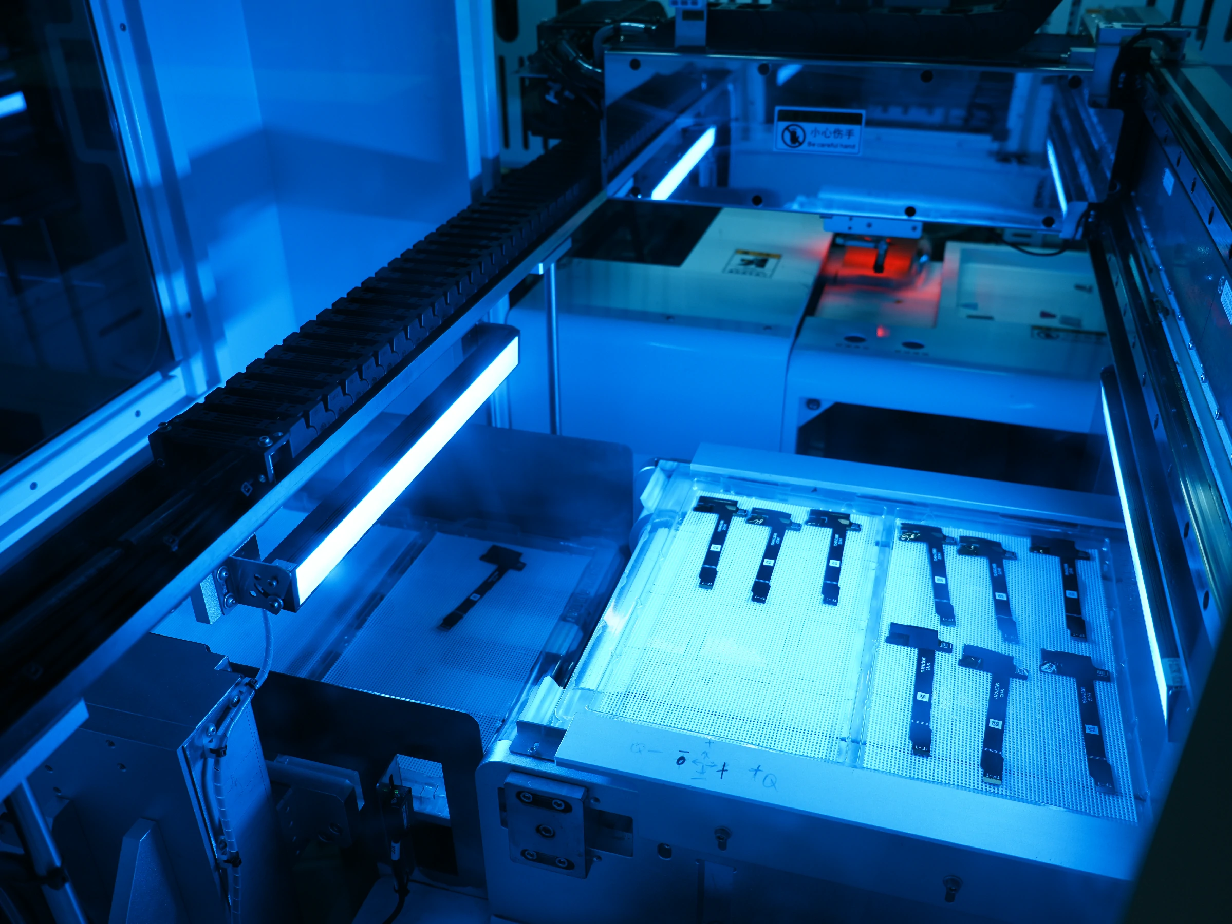
Industrial display assembly process with TFT LCD panel, touch sensor, controller board, and enclosure
Was definiert einen industriellen Touchscreen?
An industrial touch screen is designed for equipment, machines, terminals, instruments, and embedded systems that require more stable performance than a standard consumer display. It may be used in industrial control panels, medical devices, security equipment, smart terminals, vehicle-related devices, test instruments, warehouse systems, and other B2B applications.
The basic display principle may be similar to a commercial TFT LCD screen, but the design priorities are different. An industrial touch screen usually has to consider operating temperature, brightness, viewing angle, touch reliability, electrical protection, mechanical mounting, lifecycle availability, and enclosure integration. In some projects, it may also require custom cover glass, FPC adjustment, interface adaptation, controller board matching, firmware support, or specific touch tuning.
Industrial does not automatically mean the same specification for every project. A display used inside a clean indoor control terminal has different requirements from a display used in outdoor equipment, medical electronics, a vehicle dashboard, or a factory HMI system. The correct assembly process should be driven by the application environment, not by a generic product label.
Main Components in an Industrial Display Assembly
The assembly process begins with component definition. A complete industrial display assembly may include a TFT LCD panel, touch sensor, cover glass, backlight unit, bonding material, FPC cable, connector, controller board, housing, gasket, and mounting structure. Each part affects the final display performance.
The TFT LCD panel determines the active display area, resolution, brightness foundation, viewing angle, interface, and optical performance. The touch sensor determines how users interact with the device. Projected capacitive touch, often called PCAP, is commonly used when multi-touch, fast response, and a clean front-glass appearance are required. Resistive touch can still be suitable for applications where operation with gloves, stylus input, or certain wet and dusty conditions is important.
The cover glass protects the front surface and affects both appearance and durability. Its thickness, edge shape, printing area, and surface treatment should match the mechanical design of the final product. The backlight affects brightness and readability. The FPC and connectors affect assembly flexibility and reliability. The controller board handles signal conversion, touch communication, power management, and sometimes firmware behavior.
In a simple product, the display may be only a panel and touch module. In a more complete industrial HMI system, the display assembly may also include an HDMI, LVDS, MIPI, eDP, USB, or Android controller board, depending on the host system and application architecture.
Exploded view of industrial touch screen components including cover glass, LCD panel, backlight, and controller board
Step 1: Requirement Review Before Assembly
The industrial display assembly process should start before physical production. A reliable project begins with a requirement review. This step confirms whether the display module, touch structure, controller board, and mechanical design can meet the real application environment.
This step is often where costly mistakes can be prevented. For example, a display may have the correct size and resolution but use the wrong interface for the customer’s mainboard. A touch panel may work during bench testing but become unstable after cover glass is added. A display may look bright enough indoors but fail to remain readable in a high-ambient-light environment. A housing may leave too little space for the FPC bending radius, causing long-term reliability issues.
For industrial projects, the assembly process should not be separated from engineering evaluation. The earlier the display structure is reviewed, the easier it is to control cost, development time, and redesign risk.
Step 2: TFT LCD Panel and Touch Technology Selection
After the requirement review, the next step is selecting the right TFT LCD panel and touch technology. The display panel should match the required size, resolution, interface, brightness, viewing angle, and mechanical outline. The touch technology should match the operating behavior of the final product.
PCAP touch is often preferred for modern HMI panels, smart terminals, medical equipment interfaces, and consumer-style industrial devices. It supports a smooth front surface, multi-touch gestures, and a refined user experience. However, PCAP touch may require careful tuning when the device must support thick cover glass, glove operation, water on the surface, or strong electromagnetic interference.
Resistive touch is older but still relevant. It can respond to pressure from fingers, gloves, styluses, or tools. In certain industrial, outdoor, or high-interference applications, resistive touch may remain practical because it is less dependent on capacitive sensing conditions. The trade-off is that it usually does not provide the same multi-touch experience or front-glass appearance as PCAP.
The display and touch layer should be selected together. A good LCD panel with the wrong touch structure can still create poor usability. A good touch sensor installed over a low-brightness or narrow-viewing-angle panel may also fail to meet the final product requirement.
Step 3: Cover Glass and Mechanical Structure Design
Cover glass is not only a protective layer. In industrial display assembly, it affects appearance, sealing, touch sensitivity, optical clarity, mechanical fit, and user experience. The glass may require custom size, edge treatment, black border printing, logo printing, hole design, special shape, or surface treatment depending on the product.
The cover glass must also match the housing structure. If the product requires front-panel sealing, the glass, gasket, adhesive area, and enclosure must be designed as one system. If the product requires flush mounting, the glass thickness and edge shape must match the front enclosure. If the product is exposed to vibration, the bonding and mechanical support structure must prevent stress concentration.
Poor mechanical design can damage an otherwise good display module. Common problems include glass pressure on the active area, FPC over-bending, insufficient gasket compression, uneven adhesive distribution, and enclosure deformation. These issues may not appear during first power-on testing but can create failures after transportation, installation, or long-term use.
Step 4: Touch Bonding and Optical Integration
Touch bonding is one of the most important steps in industrial display assembly. The touch panel may be assembled to the LCD through air bonding or optical bonding. Air bonding leaves an air gap between the touch panel and LCD. It is simpler and cost-effective, but the air gap can increase internal reflection and reduce contrast under strong ambient light.
Optical bonding fills the gap between the touch panel and LCD with an optically clear adhesive or resin. This can improve optical performance by reducing internal reflection and increasing perceived contrast. It can also improve mechanical stability because the layers are joined more firmly. However, optical bonding requires stricter process control and is more difficult to rework.
Two common optical bonding materials are OCA and OCR. OCA, or optically clear adhesive, is a solid film material. It is suitable for many flat bonding structures and can support efficient production when the process is stable. OCR, or optically clear resin, is a liquid material that can fill gaps and adapt to some more complex structures, but it requires careful curing control and process management.
The right bonding method depends on display size, structure, touch type, operating environment, optical target, cost target, and production volume. For industrial buyers, the bonding choice should not be treated as a cosmetic option. It affects readability, assembly yield, rework difficulty, and field reliability.
Air bonding and optical bonding comparison for industrial TFT LCD touch displays
Step 5: FPC, Connector, and Cable Assembly
The FPC and connector layout determines how easily the display can be installed into the final product. In many industrial projects, the display is not used in open space. It is mounted inside a housing, connected to a mainboard, controller board, or cable harness, and surrounded by mechanical parts. If the FPC position is wrong, the display may be difficult to assemble even when the electrical specification is correct.
During assembly, the FPC should be handled carefully to avoid cracks, excessive bending, or connector stress. The cable path should avoid sharp edges, pressure points, and high-noise areas. For systems with touch communication, backlight power, and display signals, cable routing can influence signal stability.
Industrial display assemblies may use interfaces such as RGB, LVDS, MIPI, eDP, HDMI, USB, I2C, UART, or other project-specific interfaces. The interface selection should be reviewed together with the controller board or host system. A mismatch in voltage, pin definition, timing, or firmware configuration can prevent the display from working correctly even when the panel itself is suitable.
Step 6: Controller Board Integration
Many industrial display assemblies require a controller board to connect the LCD module with the customer’s system. The controller board may convert HDMI, VGA, LVDS, MIPI, eDP, USB, or other signals depending on the project. In touch display systems, the controller board may also handle touch communication, backlight control, power input, and firmware behavior.
For industrial equipment, the controller board should be selected according to the LCD interface, resolution, backlight requirements, touch interface, operating system, power input, firmware requirements, and enclosure space. It should not be assumed that one board can support every display without verification.
Electrical protection is also important. Industrial systems may operate near motors, relays, power supplies, long cables, or other noise sources. Design considerations may include grounding, shielding, ESD protection, EMI control, power filtering, signal isolation, and watchdog recovery. EMC-related standards such as the IEC 61000 series are commonly used as references for electromagnetic compatibility requirements in electrical and electronic equipment.[1]
Controller board integration is often where hardware and software requirements meet. Firmware adaptation, display timing, touch driver behavior, boot display, backlight control, and communication protocols may all affect the final user experience.
Step 7: Backlight and Brightness Control
Brightness is a central factor in industrial display assembly. A display that looks acceptable in an office may be difficult to read in a factory, warehouse, vehicle, or outdoor-facing terminal. The backlight must be selected according to the final lighting environment, display size, power budget, thermal design, and product lifetime expectation.
Industrial displays may require higher brightness, stable backlight output, or customized backlight design. In some projects, brightness control may be handled by the controller board through PWM dimming or other control methods. The goal is not always maximum brightness. Excessive brightness can increase power consumption, heat, and backlight stress. The better goal is stable readability under real operating conditions.
Backlight design should also be evaluated together with thermal structure. A brighter backlight generates more heat, and heat can affect LCD performance, LED lifetime, bonding materials, and enclosure temperature. If the display is sealed inside a compact housing, thermal planning becomes more important.
Step 8: Rugged Housing and Sealing Integration
In many industrial applications, the display assembly must be mounted into a rugged enclosure. This process requires more than placing the LCD behind a front panel. The enclosure, glass, gasket, adhesive, mounting screw positions, cable path, and mechanical support must work together.
If the product requires dust or water protection, the design may refer to IP Code principles defined under IEC 60529. The IP Code classifies degrees of protection provided by enclosures against access to hazardous parts, solid foreign objects, and water ingress.[2] However, an IP rating applies to the final enclosure or product structure, not only to the LCD panel. A display module by itself does not guarantee that the final equipment will meet a specific IP rating.
This distinction is important. A customer may ask for an “IP65 display,” but the real requirement may involve front-panel sealing, gasket compression, enclosure material, screw torque, connector sealing, cable exit design, and final product testing. If these factors are not considered, water or dust protection may fail even if the front glass looks sealed.
For rugged display integration, mechanical tolerance is also critical. Uneven pressure can cause light leakage, touch failure, glass stress, or display mura. Good assembly design should protect the active display area while supporting the cover glass and touch layer under expected use conditions.
Rugged industrial display enclosure integration with gasket sealing and controller board
Step 9: Inspection, Calibration, and Functional Testing
After physical assembly, the display should be inspected and tested before shipment or final integration. Visual inspection checks for dust, bubbles, scratches, uneven bonding, glass defects, display mura, dead pixels, light leakage, and abnormal color. Touch testing checks touch accuracy, linearity, response, multi-touch behavior when required, and stability near edges and corners.
Functional testing verifies the display signal, backlight control, touch communication, controller board behavior, power input, connector stability, and firmware behavior. For touch products, calibration or touch parameter tuning may be required depending on the touch technology, cover glass thickness, and controller configuration.
Burn-in or aging tests may be used to detect early failures. In B2B projects, the exact test plan should match the application risk level. A simple indoor display terminal and a mission-critical industrial control device should not necessarily use the same validation depth.
Reliability Testing for Industrial Display Assemblies
Industrial display assemblies may need reliability testing depending on the end product and market. Typical test categories include temperature operation, temperature storage, thermal cycling, humidity exposure, vibration, shock, ESD, EMI, and long-term operation tests. IEC 60068 provides a series of environmental testing methods for assessing whether products can perform under expected transportation, storage, and operating conditions.[3]
Reliability testing should be defined according to the final application. A display used in a smart home panel may not require the same test profile as a display used in industrial automation or vehicle-related equipment. The supplier and customer should confirm the actual test conditions rather than using broad terms such as “rugged” or “industrial grade” without definition.
For products entering regulated markets, compliance may also involve EMC, safety, environmental, or market-access requirements. FCC equipment authorization applies to RF devices before they are marketed or imported into the United States.[4] EU RoHS rules restrict the use of hazardous substances in electrical and electronic equipment to protect human health and the environment.[5] ISO 9001 is widely recognized as a quality management system standard that helps organizations maintain and improve process consistency.[6]
These standards should be understood carefully. They do not automatically prove that a specific display is suitable for every industrial environment. They provide frameworks, test references, or market requirements that may apply depending on the product, region, and customer specification.
Common Assembly Problems That Affect Industrial Displays
Many display failures are not caused by the LCD panel alone. They are caused by assembly or integration problems. Dust and bubbles in the bonding layer can reduce optical quality. Misalignment between the touch panel and LCD can affect appearance and touch accuracy. Incorrect gasket pressure can damage the glass or reduce sealing reliability. Poor cable routing can cause intermittent signal issues. Insufficient grounding or shielding can create ghost touches or unstable display behavior.
Backlight issues are also common. Uneven brightness, local dimming defects, insufficient thermal management, or incorrect backlight driving can reduce readability and long-term stability. Mechanical stress may create light leakage, display mura, or glass damage after installation.
These problems are easier to prevent during design and assembly review than to fix after the display is already integrated into the final equipment. For OEM projects, the display supplier should receive enough mechanical, electrical, and environmental information to review possible risks before mass production.
Customization in Industrial Display Assembly
Industrial display projects often require customization because standard modules do not always fit the final product structure. Customization may include brightness adjustment, cover glass design, touchscreen customization, backlight changes, FPC modification, interface adaptation, controller board matching, firmware adjustment, and mechanical structure coordination.
The most practical kundenspezifische Display- projects usually start from an existing LCD module and then adjust the surrounding structure. This can help control development cost, reduce risk, and shorten the path toward sampling and production. Developing a completely new screen size from scratch is a much more complex project and is not always the right starting point for most OEM teams.
For industrial display assembly, customization should be guided by the final use case. A medical equipment display may focus on clarity, stable touch response, and consistent supply. A smart home panel may focus on cover glass appearance, touch experience, and controller board integration. A security equipment display may focus on long operating hours and interface compatibility. A vehicle-related display may require attention to brightness, viewing angle, temperature, and installation position.
How to Prepare an RFQ for an Industrial Display Assembly
A clear RFQ helps the supplier evaluate the project accurately. Instead of only asking for a display size, buyers should provide the full context of the display application.
Useful RFQ information includes display size, resolution, interface, brightness requirement, viewing angle requirement, touch type, cover glass requirement, FPC position, controller board requirement, firmware requirement, operating temperature, installation method, enclosure structure, sealing target, application industry, annual demand, sample quantity, target schedule, and any reference model or datasheet.
If the display will be used in a demanding environment, buyers should also explain the expected exposure to dust, water, vibration, impact, chemicals, sunlight, EMI, or long operating hours. This information allows the display supplier to recommend a more suitable assembly structure instead of quoting a module that only matches the basic size.
Work With RJY Display on Industrial Display Assembly
RJY Display provides TFT LCD products, controller boards, and customization support for B2B display projects. For industrial touch screen and embedded display applications, RJY Display can support project review based on display size, interface, brightness, touch requirements, cover glass design, backlight needs, controller board matching, firmware-related requirements, and mechanical structure coordination.
If your project requires an industrial display module, a touch display assembly, a TFT LCD with controller board, or a kundenspezifische Display- solution based on an existing module, contact RJY Display with your project requirements. A clear set of technical details helps the engineering team evaluate feasibility, reduce communication time, and recommend a more suitable display assembly approach.
FAQ
Wie sieht der Prozess der industriellen Display-Montage aus?
The industrial display assembly process is the integration of a TFT LCD panel, touch sensor, cover glass, bonding layer, backlight, FPC, controller board, enclosure, and testing process into a display module or HMI-ready assembly for industrial equipment.
What is the difference between a commercial touch screen and an industrial touch screen?
A commercial touch screen is usually designed for standard indoor use, while an industrial touch screen must consider operating environment, mechanical mounting, touch reliability, electrical noise, brightness, lifecycle, and enclosure integration.
Which touch technology is better for industrial displays?
PCAP touch is suitable for modern interfaces, multi-touch operation, and clean front glass design. Resistive touch can still be useful for glove, stylus, wet, dusty, or certain high-interference applications. The better choice depends on the operating environment.
Is optical bonding required for industrial displays?
Optical bonding is not required for every project, but it can improve readability and reduce internal reflection in high-ambient-light or rugged applications. The decision depends on optical requirements, cost target, display size, and operating environment.
Can a display module alone guarantee an IP rating?
No. An IP rating applies to the final enclosure or product structure. The display, cover glass, gasket, adhesive, housing, connectors, and cable exits must be designed and tested together to support a target IP protection level.
What information should I provide for an industrial display RFQ?
You should provide display size, resolution, interface, brightness, touch type, cover glass requirements, controller board needs, operating environment, installation method, annual demand, sample quantity, and any available reference model or datasheet.