¿Enfrenta un cuello de botella en su proyecto de pantalla integrada?
No permita que la integración compleja o los problemas de la cadena de suministro retrasen su tiempo de comercialización. Reserve una consulta gratuita con el equipo experto de RJY para obtener soporte personalizado en diseño y fabricación.
Guía de compatibilidad de la placa controladora HDMI a MIPI
Publicado:
12 minutos de lectura
Actualizado:
Una placa controladora HDMI a MIPI puede conectar una fuente de video HDMI a un panel LCD MIPI DSI, pero la presencia del conector correcto no es suficiente para confirmar la compatibilidad. Dos paneles pueden usar ambos un conector FPC de 40 pines y cuatro carriles de datos MIPI, mientras requieren diferentes asignaciones de pines, temporización de video, comandos de inicialización, rieles de alimentación, secuencias de reinicio o circuitos de retroiluminación.
Para un proyecto de ingeniería, la pregunta correcta no es simplemente: “¿Este panel usa MIPI?” Es: “¿Puede esta placa controladora generar las condiciones eléctricas, de temporización, firmware y alimentación exactas que requiere este panel?”
Esta guía explica cómo evaluar una placa controladora HDMI a MIPI antes de solicitar una muestra o conectar un panel LCD desconocido.
¿Qué hace una placa controladora HDMI a MIPI?
Una placa controladora HDMI a MIPI recibe video de una fuente HDMI y lo convierte en una señal de interfaz serie de visualización MIPI adecuada para un módulo LCD compatible. MIPI DSI es una interfaz de alta velocidad definida para la comunicación entre un procesador host y un módulo de visualización.[1]
Una ruta de señal simplificada se ve así:
Fuente HDMI → Receptor HDMI o circuito puente → Transmisor MIPI DSI → IC controlador LCD y panel
El sistema de visualización completo normalmente incluye rutas adicionales que no deben confundirse con la conversión de video:
Alimentación lógica y de polarización del LCD
Señales de reinicio y habilitación del panel
Alimentación y atenuación de la retroiluminación LED
Comunicación del controlador táctil
Firmware de la placa controladora o datos de inicialización del panel
Por esto, una placa HDMI a MIPI debe tratarse como parte de un sistema de visualización, no como un adaptador de conector pasivo.
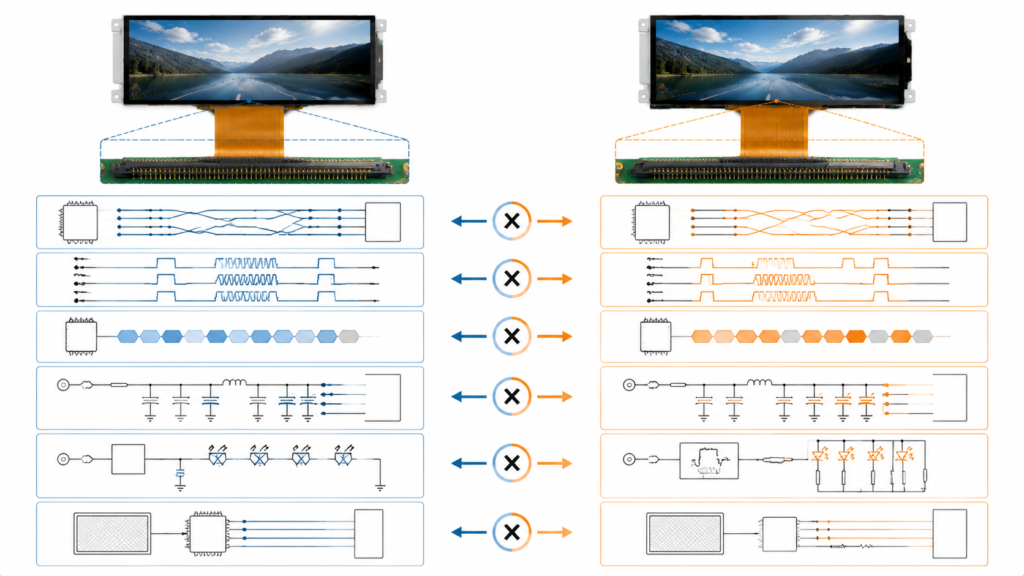
Factores de compatibilidad para dos paneles LCD MIPI DSI con conectores similares
Por qué “MIPI, 40 pines, 4 carriles” no garantiza la compatibilidad
Una descripción del conector comunica solo una pequeña parte de la información necesaria para manejar un panel. “40 pines” identifica el número de contactos, no la función asignada a cada contacto. De manera similar, “MIPI de 4 carriles” no establece la velocidad de carril requerida, el formato de píxeles, la temporización de video, el modo de operación ni la secuencia de inicialización.
MIPI DSI comúnmente utiliza un carril de reloj y uno o más carriles de datos. Una nota de aplicación de NXP describe configuraciones DSI basadas en D-PHY con un carril de reloj y hasta cuatro carriles de datos, mientras también distingue entre paneles en modo comando y modo video.[2] El controlador y el panel deben coincidir en los detalles de implementación relevantes.
Antes de aprobar la compatibilidad, revise las siguientes áreas como un solo sistema.
1. Confirmar que el panel utiliza MIPI DSI
“MIPI” no es una descripción completa de la interfaz del panel. Las especificaciones MIPI cubren varias funciones, incluyendo interfaces de visualización, cámara, táctil, control y otros dispositivos. La entrada de un LCD debe identificarse específicamente como MIPI DSI o MIPI DSI-2, no simplemente “MIPI”.”
La hoja de datos del panel debe identificar:
La interfaz de visualización como MIPI DSI
La capa física utilizada por el panel
El número de carriles de datos
El formato de píxeles compatible
Si el panel opera en modo video, modo comando o ambos
No confunda las señales de visualización MIPI DSI con las señales de cámara MIPI CSI. Sirven rutas de datos diferentes y no son intercambiables.
2. Verificar el número de carriles, el mapeo de carriles y la capacidad de los carriles
No se debe asumir automáticamente que una placa controladora anunciada como de cuatro carriles MIPI admite todos los paneles de uno, dos, tres o cuatro carriles. El hardware del puente puede tener una capacidad de carriles específica, mientras que su firmware puede estar configurado para un conjunto más limitado de disposiciones de carriles.
Confirme todo lo siguiente:
Elemento del carril
Información necesaria del panel
Información necesaria de la placa
Número de carriles de datos
Número requerido de carriles activos
Números de carriles compatibles y configurables por firmware
Carril de reloj
Pines del carril de reloj y requisitos eléctricos
Salida del carril de reloj y mapeo del conector
Polaridad del carril
Asignación de pines positivo y negativo
Si la polaridad sigue el mismo mapeo o se puede cambiar
Orden de los carriles
Ubicación de los carriles de datos en el FPC
Enrutamiento físico y cualquier reasignación de carriles compatible
Velocidad de datos por carril
Rango operativo requerido
Rango de salida del puente y firmware
Si el panel requiere dos carriles de datos pero la placa está configurada para cuatro, la compatibilidad depende de si el hardware y el firmware pueden generar el flujo de dos carriles requerido por el panel. Esto debe verificarse, no inferirse.
3. Coincidir resolución, frecuencia de actualización, temporización y formato de píxeles
La resolución es solo la matriz de píxeles visible. Un controlador también necesita la temporización de video completa, incluyendo intervalos de blanking horizontal y vertical, anchos de sincronización, front porch, back porch, reloj de píxeles, frecuencia de actualización y polaridad de señal cuando corresponda.
Por ejemplo, un panel vertical de 800 × 1280 y un panel horizontal de 1280 × 800 contienen la misma cantidad de píxeles activos, pero eso no los hace eléctrica o lógicamente equivalentes. Sus definiciones de temporización, dirección de escaneo, inicialización y orientación de entrada esperada pueden diferir.
La revisión mínima de compatibilidad debe incluir:
Parámetro
Por qué es importante
Síntoma posible cuando es incorrecto
Resolución activa
Define la matriz de píxeles visibles
Sin imagen, imagen recortada o modo no compatible
Frecuencia de actualización
Afecta el reloj de píxeles y el ancho de banda del enlace requerido
Imagen inestable o sin sincronización
Temporización horizontal y vertical
Define cómo se transmite cada fotograma
Imagen desplazada, rodante, duplicada o en blanco
Formato de píxeles
Controla cómo se empaquetan los datos de color
Colores incorrectos o sin imagen
Tasa de datos por carril
Debe transportar el flujo de píxeles requerido
Artefactos, inestabilidad o fallo del enlace
Una verificación inicial útil del ancho de banda se basa en el reloj de píxeles, los bits por píxel y el número de carriles de datos. Texas Instruments proporciona la relación básica como:
Tasa de datos aproximada por carril = reloj de píxeles × bits por píxel ÷ número de carriles[3]
Este es un cálculo de ingeniería preliminar, no una calificación completa. Aún deben considerarse el blanking, la sobrecarga de paquetes, las limitaciones del puente y el rango de tasa de carril permitido del panel.
Por lo tanto, la resolución máxima indicada de una placa controladora representa un límite superior de capacidad; no demuestra soporte para todas las temporizaciones por debajo de esa resolución.
4. Identificar el modo de video, el modo de comando y los requisitos de inicialización
Los paneles MIPI DSI pueden operar en modo de video o modo de comando. En modo de video, el host envía un flujo de píxeles en tiempo real. En modo de comando, el sistema se comunica con la pantalla mediante comandos y transacciones de datos, a menudo involucrando memoria de visualización local.[2]
Algunos paneles deben recibir primero una secuencia de inicialización específica del fabricante antes de que comience la transmisión de video. La secuencia puede configurar el IC del controlador, el formato de píxeles, la orientación, el comportamiento de energía, la configuración gamma, la temporización, el estado de suspensión o el estado de habilitación de la pantalla.
La documentación del controlador MIPI DSI de NXP refleja esta distinción: se inicializa el periférico DSI, se configura la temporización D-PHY, se pueden realizar transferencias de comandos y luego se puede iniciar el modo de video con la configuración DPI requerida.[4]
Antes de seleccionar una placa controladora, determine si el panel requiere:
Comandos MIPI DCS
Comandos de inicialización específicos del proveedor
Una secuencia de reinicio particular
Transmisión de comandos de baja potencia antes de video de alta velocidad
Operación en modo de ráfaga o no ráfaga de video
Una configuración específica del IC del controlador
Si el proveedor del panel no puede proporcionar el código de inicialización o un diseño de referencia probado, la adaptación del firmware puede volverse significativamente más difícil.
5. Comparar la definición completa de pines del FPC
Nunca conecte un panel basándose únicamente en el paso y el número de pines del conector. La definición completa de los pines debe compararse línea por línea.
Un conector de 40 pines con paso de 0.5 mm puede transportar una combinación de:
Carriles de reloj y datos MIPI
Voltaje lógico del LCD
Rieles de polarización positiva y negativa del panel
Tierra (GND)
Reinicio y habilitación
Conexiones de ánodo y cátodo de la retroiluminación
PWM o habilitación de retroiluminación
Alimentación y comunicación del controlador táctil
Pines de identificación o prueba
El lado de contacto del FPC, la dirección de inserción, la orientación del conector y el enrutamiento del cable también deben coincidir con el diseño mecánico. Una secuencia de pines reflejada puede colocar alimentación en un pin de señal incluso cuando el conector parece encajar físicamente.
6. Verificar los requisitos de alimentación, reinicio y retroiluminación del panel
MIPI DSI describe la interfaz de comunicación de la pantalla; no elimina los requisitos de alimentación específicos del panel. El LCD puede requerir varios rieles lógicos o analógicos, y el IC del controlador puede especificar un orden definido para aplicar alimentación, reinicio, inicialización, salida de suspensión, encendido de pantalla y habilitación de retroiluminación.
En el ejemplo de NXP para activar un LCD DSI, la implementación incluye configurar la alimentación del panel, el reinicio, el GPIO de retroiluminación, los parámetros de temporización y la polaridad de la señal antes de la operación normal.[2]
Revise estos elementos por separado:
Voltaje y corriente lógicos del LCD
Rieles de polarización positiva y negativa requeridos
Nivel de voltaje y temporización de reinicio
Secuencia de encendido y apagado
Voltaje directo y corriente de la retroiluminación
Lógica de habilitación de retroiluminación
Frecuencia y polaridad del PWM, si se requiere atenuación
Condiciones térmicas al brillo previsto
Una retroiluminación funcional no demuestra que la comunicación MIPI esté funcionando. Por el contrario, un LCD correctamente inicializado puede permanecer visualmente oscuro si el circuito de retroiluminación no está habilitado.
7. Confirmar la fuente HDMI y el modo de salida
La fuente HDMI debe suministrar un modo de video que la placa controladora pueda recibir y traducir a la temporización requerida por el panel. Una laptop, PC, Raspberry Pi o computadora embebida puede seleccionar su modo de salida basándose en la identificación de la pantalla, la configuración del sistema operativo o un modo definido manualmente.
Antes de las pruebas, confirme:
Las resoluciones y frecuencias de actualización de salida disponibles de la fuente HDMI
Los modos de entrada compatibles con el firmware de la placa puente
Si la placa realiza escalado o espera un modo de entrada nativo específico
Si la temporización vertical debe ser generada por la fuente
Si la rotación es manejada por el software de la fuente, el firmware del puente o el IC del controlador de la pantalla
No asuma que una placa HDMI a MIPI escala, rota o convierte automáticamente cada modo de fuente. Estas funciones deben confirmarse para el firmware real.
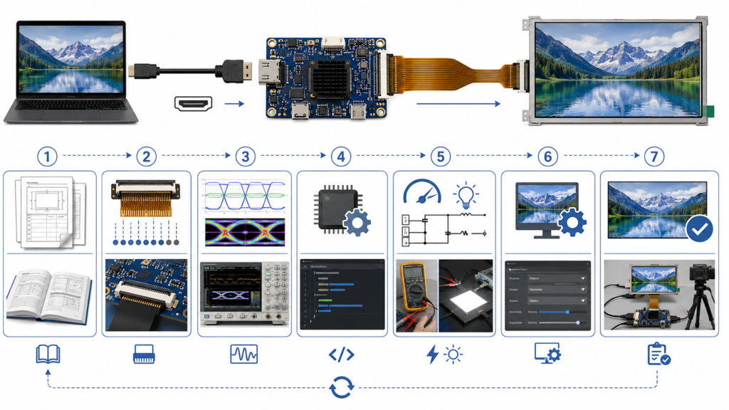
Flujo de trabajo de ingeniería para verificar la compatibilidad de paneles LCD HDMI a MIPI
8. Tratar el táctil como una interfaz separada
Convertir video HDMI a MIPI DSI no convierte ni habilita automáticamente la entrada táctil. Un panel táctil capacitivo puede usar USB, I2C u otra conexión, mientras que su controlador puede requerir soporte de controlador y firmware del lado del host.
MIPI también mantiene una familia separada de especificaciones para la integración táctil, lo que ilustra que la transmisión de la pantalla y la entrada táctil son funciones de sistema distintas.[5]
Para un proyecto con fuente HDMI, verifique:
El modelo del controlador táctil
La interfaz táctil, como USB o I2C
Soporte requerido del controlador host
Requisitos de alimentación táctil
Mapeo de coordenadas y orientación de la pantalla
Si la placa controladora expone o procesa la señal táctil
Revisión de compatibilidad para la placa RJY-HDMI-MIPI-V1
La página de producto actual de RJY Display identifica la RJY-HDMI-MIPI-V1 como una placa controladora HDMI a MIPI que utiliza un chip principal LT6911C. La configuración publicada describe una conexión LCD MIPI de cuatro carriles, un conector FPC de 40 pines y 0.5 mm, y soporte para resoluciones de hasta 1920 × 1200.[6]
Elemento de placa publicado
Lo que establece
Lo que aún requiere confirmación
Función HDMI a MIPI
La placa puentea una fuente HDMI a una salida LCD MIPI
Modos de entrada HDMI compatibles y firmware específico del panel
Salida LCD MIPI de cuatro carriles
La configuración de salida indicada utiliza cuatro carriles de datos MIPI
Velocidad de carril del panel, orden de carriles, polaridad y modo
Conector FPC de 40 pines y 0.5 mm
El formato físico del conector
Compatibilidad completa pin a pin y orientación del FPC
Resolución máxima de hasta 1920 × 1200
Un límite de resolución publicado
Temporización exacta de resolución, frecuencia de actualización y formato de píxeles
Soporte de retroiluminación LED
La placa incluye capacidad relacionada con la retroiluminación
Compatibilidad con la cadena LED real del panel y los requisitos de atenuación
Estas especificaciones son útiles para una selección inicial, pero no se debe declarar un panel como compatible hasta que se hayan revisado su hoja de datos, definición de pines, información de inicialización, temporización y requisitos de alimentación.
Ejemplo: ¿Es compatible un panel de 800 × 1280, cuatro carriles y 40 pines?
No hay suficiente información disponible para responder solo con esas tres especificaciones.
El panel pasa una selección inicial porque su resolución está por debajo del máximo publicado de la placa, y su número de carriles y formato de conector indicados parecen relevantes. Sin embargo, la confirmación de ingeniería aún requiere:
El modelo completo del panel y su hoja de datos
La definición exacta de los 40 pines
La orientación de contacto del FPC
Temporización horizontal y vertical
La frecuencia de actualización requerida
El formato de píxeles y la tasa de datos por carril
El requisito de modo de video o modo de comando
El IC del controlador y la secuencia de inicialización
Los rieles de alimentación lógica y de polarización
La secuencia de reinicio y alimentación
El voltaje, la corriente, la habilitación y el método de atenuación de la retroiluminación
La interfaz del controlador táctil, si se incluye táctil
La compatibilidad debe confirmarse con respecto a estos elementos antes de conectar una placa de muestra al panel.
Flujo de trabajo recomendado para emparejar paneles HDMI a MIPI
Recopile la hoja de datos original del panel. Un listado de revendedor o una fotografía del conector no son suficientes.
Confirme la interfaz y el modo de operación DSI. Identifique el número de carriles, el formato de píxeles, el modo de video o comando, y los requisitos de inicialización.
Compare la definición de pines del FPC. Verifique cada señal y pin de alimentación, incluida la orientación del conector.
Revise la temporización y el ancho de banda. Compare la resolución, la frecuencia de actualización, el reloj de píxeles, el blanking, la velocidad de carril y los límites del puente.
Revise los circuitos de alimentación y retroiluminación. Confirme los rieles lógicos, los rieles de polarización, la secuenciación, el reinicio, la corriente LED y la atenuación.
Confirme la disponibilidad del firmware. Determine si el firmware existente soporta el panel o debe adaptarse.
Verifique el modo de la fuente HDMI. Confirme que la fuente puede producir la temporización de entrada requerida.
Pruebe una combinación de muestra controlada. Utilice juntos el panel, la placa, el cable, el firmware y la configuración de alimentación confirmados.
Alimentación de la placa, rieles de alimentación del panel, señales de habilitación, orientación del conector y estado de protección
Retroiluminación encendida pero sin imagen
Inicialización DSI, secuencia de reinicio, temporización, configuración de carriles, firmware y habilitación del panel
Imagen desplazada o con desplazamiento vertical
Sincronización horizontal y vertical, reloj de píxeles, configuración de sincronización y frecuencia de actualización
Colores incorrectos
Formato de píxeles, orden de colores, profundidad de bits y configuración del IC controlador
Artefactos intermitentes
Velocidad de línea, integridad de la señal, calidad del FPC, conexión a tierra, estabilidad de la alimentación y margen de sincronización
El video funciona, pero el táctil no
Interfaz táctil, controlador del host, conexión USB o I2C, alimentación, mapeo y orientación
Imagen correcta en la orientación incorrecta
Rotación de la fuente, configuración de exploración del panel, comandos de inicialización y capacidad del firmware del puente
Qué enviar para una revisión de compatibilidad de ingeniería
Proporcionar documentación completa antes del muestreo reduce la prueba y error innecesarios. Prepare:
Número de modelo completo del panel LCD
Hoja de datos original del panel
Tabla de temporización del panel
Definición de pines del FPC y dibujo del conector
Modelo del IC controlador
Archivo de comandos de inicialización o código de referencia
Especificación de la retroiluminación
Información del panel táctil y del controlador táctil
Dispositivo fuente HDMI y modos de salida disponibles
Orientación de pantalla requerida
Aplicación objetivo y entorno operativo
Cantidad de muestras y demanda de producción esperada
Si la hoja de datos original o la secuencia de inicialización no están disponibles, identifique esa limitación al inicio de la revisión. Una fotografía y la resolución nominal por sí solas rara vez son suficientes para una adaptación confiable del panel MIPI.
Solicitar una revisión de compatibilidad HDMI a MIPI
RJY Display puede revisar su panel LCD MIPI, fuente HDMI, conector, temporización, retroiluminación, táctil y requisitos de firmware antes de la selección de muestras. La compatibilidad se evalúa para la configuración real del panel y la placa controladora, no solo por el tamaño del conector.
¿Significa el mismo conector de 40 pines que un panel LCD es compatible?
No. La misma cantidad de pines y paso del conector no garantizan la misma definición de pines. La alimentación, tierra, líneas MIPI, reinicio, retroiluminación, táctil y señales de control deben compararse pin por pin antes de la conexión.
¿Puede una placa HDMI a MIPI de cuatro líneas alimentar un panel MIPI de dos líneas?
Solo si el hardware y el firmware del puente admiten la configuración de dos líneas del panel, la temporización, el formato de píxeles y la velocidad de línea requerida. La capacidad de cuatro líneas por sí sola no confirma la compatibilidad con dos líneas.
¿Se confirma la compatibilidad si la resolución del panel es inferior a la resolución máxima de la placa?
No. La resolución máxima es solo un límite de capacidad inicial. El reloj de píxeles exacto, los intervalos de blanking, la frecuencia de actualización, el modo DSI, el formato de píxeles, la velocidad de línea, la secuencia de inicialización y el firmware también deben coincidir.
¿Una placa controladora HDMI a MIPI admite automáticamente la entrada táctil?
No. El táctil normalmente utiliza un controlador separado y una ruta de comunicación como USB o I2C. La interfaz táctil, el controlador del host, la alimentación, el mapeo de coordenadas y la orientación deben revisarse por separado.
¿Qué documentos se necesitan para confirmar la compatibilidad del LCD MIPI?
La revisión debe incluir la hoja de datos original del panel, la definición completa de pines del FPC, la tabla de temporización, el IC controlador, los comandos de inicialización, la secuencia de alimentación, la especificación de la retroiluminación, los detalles del controlador táctil y la información sobre la fuente HDMI.
¿Puede aprobarse un panel MIPI de 800 × 1280 y cuatro líneas solo por su resolución y cantidad de líneas?
No. Esas especificaciones son útiles para una selección inicial, pero la aprobación aún requiere el pinout del panel, la temporización, el modo de operación, la secuencia de inicialización, los rieles de alimentación, los requisitos de retroiluminación, el soporte del firmware y la configuración de salida de la fuente.
¿Aún no sabe qué pantalla se adapta a su proyecto?
Hable con el equipo de ingeniería de RJY para obtener asesoramiento sobre compatibilidad de pantallas, revisión de placas controladoras y discusión sobre personalización.