Facing a bottleneck in your Embedded Display Project?
Don’t let complex integration or supply chain issues slow your time-to-market. Book a free consultation with the RJY expert team for tailored design and manufacturing support.

In the digital age, Thin-Film Transistor Liquid Crystal Displays (TFT-LCDs) have become ubiquitous, powering devices such as smartphones, tablets, televisions, and computer monitors. Renowned for their superior display quality, high resolution, accurate color reproduction, and extended lifespan, TFT-LCDs have established themselves as the preferred choice across various industries.
A TFT liquid crystal display, often called a TFT-LCD or TFT LCD, is one of the most widely used display technologies in embedded devices, industrial HMIs, smart home panels, vehicle-related displays, security equipment, and consumer electronics. Its performance comes from the combination of liquid crystal light modulation, thin-film transistor pixel control, color filters, polarizers, backlight design, driver ICs, and display timing control.
Understanding the structure and driving principle of a TFT-LCD helps engineers and B2B buyers make better display decisions. It explains why the same display size can behave differently depending on resolution, panel type, backlight design, interface, controller board, touch panel, FPC layout, and firmware configuration.
This guide explains the main structure of a TFT liquid crystal display, how pixels are driven, how images are formed, and what buyers should check when selecting a TFT LCD module for a product design.
A TFT liquid crystal display is an active-matrix LCD that uses thin-film transistors to control pixels. Each pixel or subpixel is controlled through transistor circuitry, allowing the display to update image information more accurately than older passive-matrix LCD designs.
The LCD part refers to the liquid crystal display structure. Liquid crystal material does not emit light by itself. Instead, it controls how light passes through the display. In most modern TFT-LCD modules, an LED backlight provides the light source.
The TFT part refers to the active-matrix transistor layer. This layer helps control pixel voltage, which changes the orientation of liquid crystal molecules and modulates how much light passes through each pixel area.
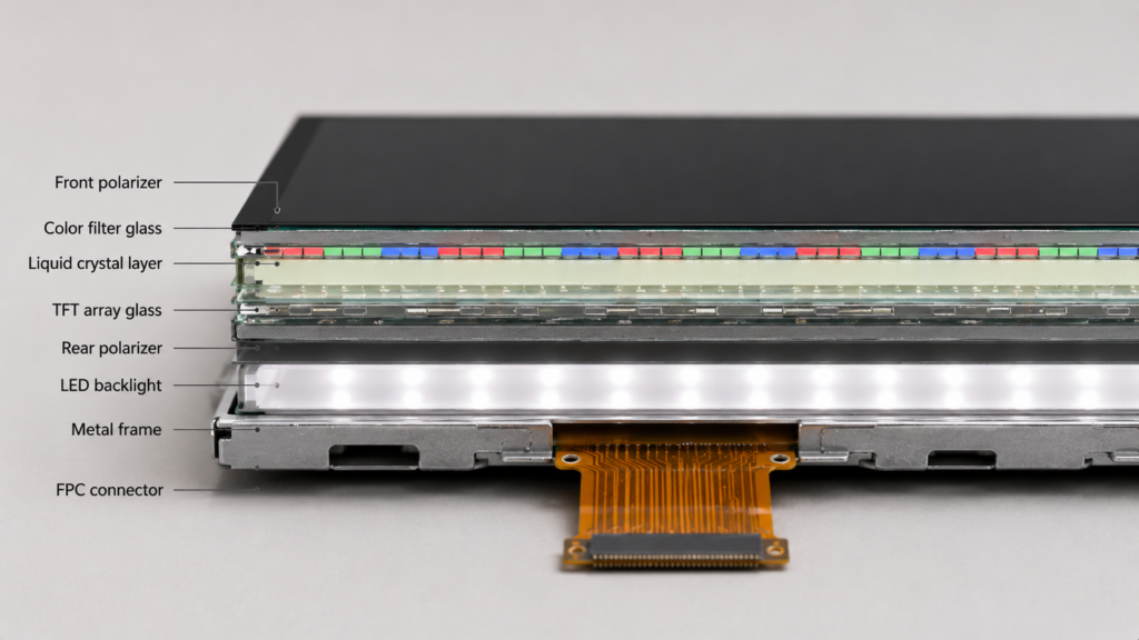
A TFT-LCD module is made from several optical, electrical, and mechanical layers. The exact structure varies by product, but a typical module includes glass substrates, polarizers, a TFT array, liquid crystal layer, color filter, driver ICs, FPC, backlight unit, frame, and sometimes a touch panel or cover glass.
| Component | Main Function | Why It Matters |
|---|---|---|
| Front polarizer | Controls light polarization before viewing | Affects image formation and optical performance |
| Color filter glass | Provides red, green, and blue subpixel filters | Creates full-color images |
| Liquid crystal layer | Changes light transmission under voltage | Controls pixel brightness |
| TFT array glass | Contains thin-film transistors and pixel electrodes | Controls pixel-level voltage |
| Rear polarizer | Works with front polarizer and liquid crystal layer | Enables light modulation |
| LED backlight unit | Provides light for the LCD | Affects brightness, power, heat, and thickness |
| Driver IC | Sends row and column signals to the panel | Controls image addressing and timing |
| FPC and connector | Connects display signals and power to the system | Affects integration and compatibility |
| Frame or mechanical structure | Supports the LCD cell and backlight | Affects mounting and durability |
| Touch panel and cover glass | Adds user input and front protection when required | Affects interaction, appearance, and mechanical fit |
TFT-LCDs use glass substrates as the base structure for the display cell. One glass substrate carries the TFT array. The other carries the color filter. The liquid crystal layer is placed between these two substrates.
The glass must be flat, clean, and dimensionally stable. Any problem in alignment, contamination, or mechanical stress can affect display quality. For finished modules, the glass structure must also be protected during mechanical integration because excessive pressure or bending can create visible defects.
The TFT array layer is one of the most important parts of a TFT-LCD. It contains thin-film transistors, pixel electrodes, signal lines, gate lines, and related structures on the glass substrate.
Each pixel is controlled by switching the relevant TFT. The TFT works like an electrical switch that charges the pixel electrode to a required voltage. This voltage influences the liquid crystal orientation in that pixel area.
The TFT array allows the display to control many pixels with much better precision than passive-matrix LCDs. This is why TFT-LCDs are suitable for color graphical interfaces, higher resolutions, touch panels, industrial displays, dashboards, and embedded systems.
The liquid crystal layer sits between the TFT array glass and the color filter glass. Liquid crystal molecules change their alignment when an electric field is applied.
This change in molecular alignment controls how polarized light passes through the display. Depending on the applied voltage, each pixel area allows more or less light to pass. This creates different brightness levels.
The liquid crystal layer is responsible for light modulation, but it does not create light. That is why a transmissive TFT-LCD needs a backlight.
A color TFT-LCD uses red, green, and blue subpixels. The color filter layer separates white backlight into these color components. By controlling the brightness of red, green, and blue subpixels, the display can create a wide range of colors.
Color filter quality affects color appearance, brightness, contrast, and uniformity. In practical product selection, buyers should remember that color performance depends not only on the display label but also on panel type, backlight, optical films, viewing angle, and calibration.
Polarizers are required for normal LCD image formation. A TFT-LCD usually includes a rear polarizer and a front polarizer. These polarizers work with the liquid crystal layer to control the passage of light.
The backlight first passes through the rear polarizer, then through the liquid crystal layer, color filter, and front polarizer. The liquid crystal alignment determines whether light is blocked or transmitted through the polarizer system.
Polarizer quality can affect brightness, contrast, viewing behavior, and appearance. It is also one reason why pressure, scratches, or surface damage can affect display performance.
Most modern TFT-LCD modules use an LED backlight unit. Since the LCD cell does not emit light, the backlight provides the illumination needed to make the image visible.
A backlight unit may include LEDs, light guide plate, diffuser films, prism films, reflector, and mechanical support parts. The goal is to distribute light evenly across the display area.
Backlight design affects:
For high-brightness or industrial projects, backlight design should be reviewed early because stronger brightness may require more power and better thermal planning.
The TFT-LCD panel needs driver ICs to control the rows and columns of pixels. These driver ICs receive image and timing signals from the host system or controller board and convert them into the required panel-driving signals.
The FPC, or flexible printed circuit, connects the LCD module to the customer’s mainboard or controller board. It may carry display signals, power, backlight connections, touch signals, and control lines depending on the module design.
For B2B projects, the interface is a major selection point. A TFT-LCD module may use RGB, LVDS, MIPI, SPI, MCU, HDMI, eDP, or another interface depending on the display and system configuration. The correct interface must be confirmed based on resolution, timing, pin definition, voltage, backlight, touch, and controller board requirements.
A TFT-LCD image is built from pixels. Each color pixel is usually divided into red, green, and blue subpixels. Each subpixel is controlled by a transistor and a liquid crystal area.
When the display driver sends a signal, the TFT switch charges the pixel electrode. The voltage across the liquid crystal layer changes the orientation of the liquid crystal molecules. This changes how much light passes through the subpixel.
By controlling the voltage of red, green, and blue subpixels, the display creates different colors and brightness levels. When millions of subpixels are controlled together, the screen forms a complete image.
The driving principle of a TFT-LCD is based on scanning rows and writing pixel data to columns. The display driver activates one row at a time through the gate lines. At the same time, source drivers send image data voltages to the column lines.
When a row is selected, the TFT switches in that row turn on and allow the pixel electrodes to charge. After the row is written, the TFT switches turn off and the pixel voltage is held until the next refresh cycle.
This active-matrix method allows the display to control many pixels efficiently and maintain image information between refresh cycles. It is one of the main reasons TFT-LCDs can support high-resolution color images and graphical interfaces.
The gate driver controls row selection. It turns on one row or group of rows according to the panel timing sequence. The source driver sends grayscale voltage levels or data signals to the columns.
The display timing must be accurate. If the timing, voltage, or signal format does not match the LCD panel requirements, the screen may show no image, flickering, incorrect colors, unstable display behavior, or image artifacts.
This is why controller board matching is important. The display panel, interface, resolution, driver IC, timing, backlight, touch interface, and firmware must be reviewed together.
A TFT-LCD is refreshed repeatedly. During each refresh cycle, the display writes new image data to the pixels. Refresh timing must be stable so that image information is written correctly.
Important timing-related factors include:
Timing mismatch can cause image shift, flickering, rolling, blank screen, color errors, or unstable operation. For this reason, TFT-LCD integration is not only a mechanical task. It also requires electrical and firmware compatibility.
The LCD panel and backlight are related but driven differently. The TFT array controls the image. The LED backlight provides illumination. Brightness control is often handled by changing the backlight current or using dimming control depending on the design.
Backlight driving affects power consumption, heat, brightness stability, and visual comfort. For high-brightness displays, the backlight circuit and thermal structure must be reviewed carefully.
In a product design, it is important to confirm the backlight voltage, current, connector pins, dimming method, and whether the controller board or mainboard can support the required backlight control.
A TFT-LCD module may be used with a resistive touch panel, capacitive touch panel, cover glass, and controller board. These parts are not always part of the LCD cell itself, but they are often part of the final display solution.
Touch integration requires attention to touch type, touch controller, interface, driver support, cover glass structure, grounding, noise environment, and mechanical fit.
Controller board integration requires attention to LCD interface, resolution, timing, backlight, touch signal, firmware, power input, operating system, and application behavior. This is especially important when the customer wants an HDMI, VGA, USB, LVDS, MIPI, eDP, or Android-based display solution.
A TFT-LCD driver system must match the display panel and final product requirements. Driver system design affects image stability, signal quality, power consumption, thermal behavior, and long-term reliability.
| Design Factor | Why It Matters | What Buyers Should Check |
|---|---|---|
| Signal integrity | Poor signals can cause display artifacts or instability | Cable length, shielding, connector quality, interface type |
| Timing compatibility | The LCD must receive correct timing signals | Resolution, pixel clock, sync, data enable, driver IC requirements |
| Power design | Incorrect power can cause failure or instability | Logic voltage, backlight voltage, current, power sequencing |
| Backlight control | Brightness affects readability, power, and heat | LED current, dimming method, thermal structure |
| Thermal management | Heat can affect reliability and optical performance | Enclosure design, high-brightness use, airflow or heat path |
| EMI and grounding | Noise can affect display and touch performance | Cable routing, shielding, grounding, system environment |
| Firmware support | Controller behavior may require adaptation | Boot display, timing setup, touch support, system requirements |
Understanding TFT-LCD structure and driving principle helps buyers avoid common selection mistakes. A display module is not defined only by diagonal size. The LCD panel, driver IC, FPC, interface, backlight, touch panel, and controller board must be compatible.
For example, two displays may both be 7 inches, but they may have different resolutions, interfaces, FPC pin definitions, backlight current requirements, touch structures, viewing angles, and controller board needs. They are not automatically interchangeable.
Before selecting a TFT-LCD module, buyers should check:
RJY Display supports TFT LCD modules, controller boards, and custom display solution discussions for engineering-driven B2B projects. The structure and driving principle of TFT-LCDs are directly related to how a module should be selected and integrated.
RJY Display can review project requirements such as size, resolution, interface, brightness, touch panel, cover glass, backlight, FPC, controller board, firmware, and mechanical structure coordination. For many custom projects, the practical approach is to start from an existing display module and adjust the related parts around it.
If your project needs a TFT LCD module, touch display, high-brightness display, controller board, interface matching, firmware support, or custom display discussion, prepare your display requirements before inquiry.
Send Your TFT-LCD Project Requirements
The structure of a TFT liquid crystal display includes glass substrates, TFT array, liquid crystal layer, color filter, polarizers, backlight unit, driver ICs, FPC, and mechanical support parts. These components work together to control light and form images.
The driving principle is based on active-matrix pixel control. Gate drivers select rows, source drivers write image data to columns, and TFT switches help each pixel hold the required voltage until the next refresh cycle. The liquid crystal layer then modulates light from the backlight to create visible brightness and color.
For B2B display projects, understanding this structure and driving principle helps buyers make better decisions about resolution, interface, backlight, touch, controller board, firmware, mechanical design, and customization feasibility. A good TFT-LCD selection is not only about choosing a screen size. It is about matching the complete display system to the product requirement.
A typical TFT-LCD includes polarizers, glass substrates, TFT array, liquid crystal layer, color filter, LED backlight unit, driver ICs, FPC, and mechanical support parts. Some modules also include touch panels and cover glass.
A TFT-LCD is driven by selecting rows through gate drivers and writing image data to columns through source drivers. TFT switches charge pixel electrodes, and the liquid crystal layer changes light transmission according to the applied voltage.
Liquid crystal material does not emit light by itself. A transmissive TFT-LCD needs a backlight, usually LED-based, to provide the light that passes through the LCD structure to form a visible image.
The TFT layer contains thin-film transistors that act as switches for pixels or subpixels. It helps control pixel voltage accurately, enabling active-matrix display operation.
The color filter creates red, green, and blue subpixels. By controlling the brightness of these subpixels, the display can generate full-color images.
Timing controls how rows and columns are addressed during refresh. Incorrect timing can cause no image, flickering, shifted image, color errors, or unstable display behavior.
The controller board provides or converts display signals, timing, power, backlight control, touch support, and sometimes firmware behavior. It must match the LCD panel’s resolution, interface, timing, voltage, and backlight requirements.
Buyers should check display size, resolution, interface, brightness, viewing angle, FPC, connector, backlight voltage and current, touch requirement, controller board compatibility, firmware needs, mechanical structure, and operating environment.
Share your display size, resolution, interface, brightness, touch requirement, controller board requirement, and application environment.
Continue reading related display technology guides and application references.
Explore product pages related to this article topic.

Talk to RJY’s engineering team for display matching, controller board review, and customization discussion.









