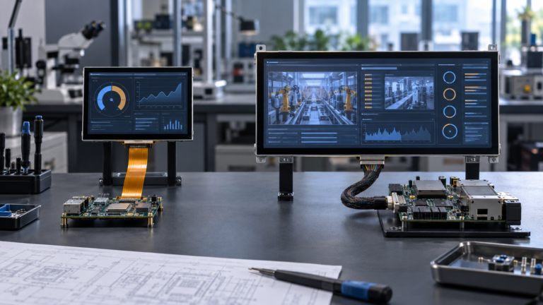
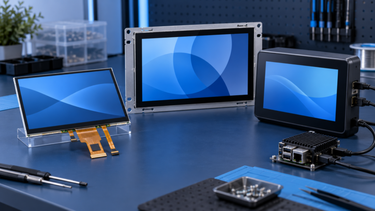
Incontri un collo di bottiglia nel tuo progetto di display embedded?
Non lasciare che integrazioni complesse o problemi di supply chain rallentino il tuo time-to-market. Prenota una consulenza gratuita con il team di esperti RJY per un supporto su misura in progettazione e produzione.
Guida alla compatibilità della scheda controller HDMI-MIPI
Pubblicato:
12 minuti di lettura
Aggiornato:
Una scheda di controllo HDMI-to-MIPI può collegare una sorgente video HDMI a un pannello LCD MIPI DSI, ma la presenza del connettore corretto non è sufficiente per confermare la compatibilità. Due pannelli possono entrambi utilizzare un connettore FPC a 40 pin e quattro linee dati MIPI, richiedendo però diverse assegnazioni dei pin, temporizzazioni video, comandi di inizializzazione, tensioni di alimentazione, sequenze di reset o circuiti di retroilluminazione.
Per un progetto ingegneristico, la domanda corretta non è quindi semplicemente: “Questo pannello utilizza MIPI?” bensì: “Questa scheda di controllo può generare le condizioni elettriche, di temporizzazione, firmware e di alimentazione esatte richieste da questo pannello?”
Questa guida spiega come valutare una scheda di controllo HDMI-to-MIPI prima di ordinare un campione o collegare un pannello LCD sconosciuto.
Cosa fa una scheda di controllo HDMI-to-MIPI?
Una scheda di controllo HDMI-to-MIPI riceve video da una sorgente HDMI e lo converte in un segnale MIPI Display Serial Interface adatto a un modulo LCD compatibile. MIPI DSI è un'interfaccia ad alta velocità definita per la comunicazione tra un processore host e un modulo display.[1]
Un percorso del segnale semplificato si presenta così:
Sorgente HDMI → ricevitore HDMI o circuito bridge → trasmettitore MIPI DSI → circuito integrato driver LCD e pannello
Il sistema di visualizzazione completo include normalmente percorsi aggiuntivi che non devono essere confusi con la conversione video:
Alimentazione logica e di polarizzazione LCD
Segnali di reset e abilitazione del pannello
Alimentazione e regolazione della luminosità della retroilluminazione LED
Comunicazione del controller touch
Firmware della scheda di controllo o dati di inizializzazione del pannello
Questo è il motivo per cui una scheda HDMI-to-MIPI dovrebbe essere trattata come parte di un sistema di visualizzazione, non come un adattatore passivo per connettori.
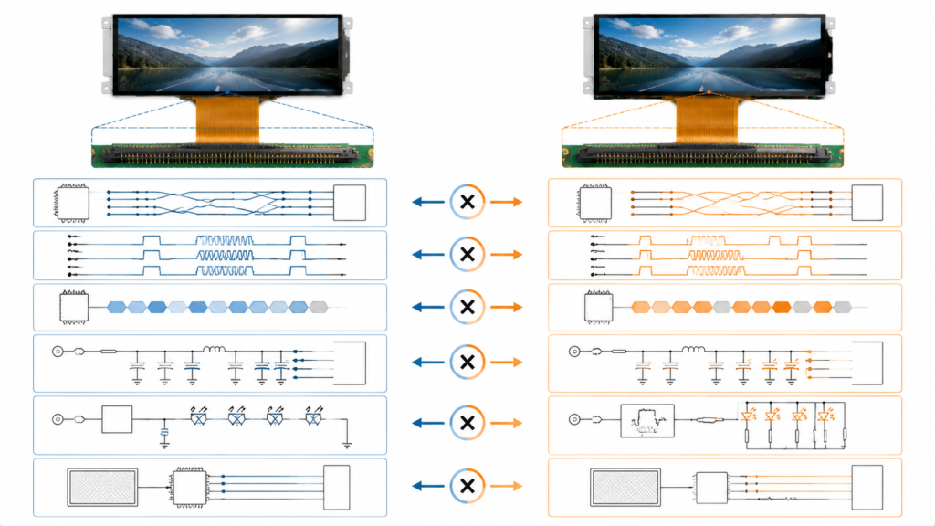
Fattori di compatibilità per due pannelli LCD MIPI DSI con connettori simili
Perché “MIPI, 40 pin, 4 linee” non garantisce la compatibilità
Una descrizione del connettore comunica solo una piccola parte delle informazioni necessarie per pilotare un pannello. “40 pin” identifica il numero di contatti, non la funzione assegnata a ciascun contatto. Allo stesso modo, “MIPI a 4 linee” non stabilisce la velocità di linea richiesta, il formato pixel, la temporizzazione video, la modalità operativa o la sequenza di inizializzazione.
MIPI DSI utilizza comunemente una linea di clock e una o più linee dati. Una nota applicativa NXP descrive configurazioni DSI basate su D-PHY con una linea di clock e fino a quattro linee dati, distinguendo inoltre tra pannelli in modalità comando e modalità video.[2] Il controller e il pannello devono concordare sui dettagli implementativi pertinenti.
Prima di approvare la compatibilità, esaminare le seguenti aree come un unico sistema.
1. Confermare che il pannello utilizzi MIPI DSI
“MIPI” non è una descrizione completa dell'interfaccia del pannello. Le specifiche MIPI coprono diverse funzioni, tra cui display, fotocamera, touch, controllo e altre interfacce per dispositivi. Un ingresso display LCD dovrebbe essere normalmente identificato specificamente come MIPI DSI o MIPI DSI-2, non semplicemente “MIPI.”
La scheda tecnica del pannello dovrebbe identificare:
L'interfaccia display come MIPI DSI
Il livello fisico utilizzato dal pannello
Il numero di linee dati
Il formato pixel supportato
Se il pannello opera in modalità video, modalità comando o supporta entrambe
Non confondere i segnali display MIPI DSI con i segnali fotocamera MIPI CSI. Servono percorsi dati diversi e non sono intercambiabili.
2. Verificare il numero di linee, il mapping delle linee e la capacità delle linee
Una scheda di controllo pubblicizzata come scheda MIPI a quattro linee non dovrebbe essere automaticamente considerata in grado di supportare ogni pannello a una, due, tre o quattro linee. L'hardware del bridge può avere una capacità di linea specifica, mentre il suo firmware può essere configurato per un insieme più ristretto di disposizioni delle linee.
Confermare tutti i seguenti elementi:
Elemento della linea
Informazioni necessarie dal pannello
Informazioni necessarie dalla scheda
Numero di linee dati
Numero richiesto di linee attive
Numero di linee supportate e configurabili tramite firmware
Linea di clock
Pin della linea di clock e requisiti elettrici
Uscita della linea di clock e mapping del connettore
Polarità della linea
Assegnazione dei pin positivo e negativo
Se la polarità segue lo stesso mapping o può essere modificata
Ordine delle linee
Posizione delle linee dati sul connettore FPC
Routing fisico e qualsiasi ri-mappatura delle linee supportata
Velocità dati per linea
Intervallo operativo richiesto
Intervallo di uscita del bridge e del firmware
Se il pannello richiede due linee dati ma la scheda è configurata per quattro, la compatibilità dipende dal fatto che l'hardware e il firmware possano generare il flusso a due linee richiesto dal pannello. Dovrebbe essere verificato, non dedotto.
3. Abbinare risoluzione, frequenza di aggiornamento, temporizzazione e formato pixel
La risoluzione è solo la matrice di pixel visibile. Un controller necessita anche della temporizzazione video completa, inclusi gli intervalli di blanking orizzontale e verticale, le larghezze di sincronizzazione, il front porch, il back porch, il clock pixel, la frequenza di aggiornamento e la polarità del segnale, ove applicabile.
Ad esempio, un pannello verticale da 800 × 1280 e un pannello orizzontale da 1280 × 800 contengono lo stesso numero di pixel attivi, ma ciò non li rende elettricamente o logicamente equivalenti. Le loro definizioni di temporizzazione, direzione di scansione, inizializzazione e orientamento di ingresso previsto possono differire.
La revisione minima di compatibilità dovrebbe includere:
Parametro
Perché è importante
Possibile sintomo in caso di errore
Risoluzione attiva
Definisce la matrice di pixel visibili
Nessuna immagine, immagine ritagliata o modalità non supportata
Frequenza di aggiornamento
Influisce sul clock dei pixel e sulla larghezza di banda del collegamento richiesta
Immagine instabile o assenza di sincronizzazione
Temporizzazione orizzontale e verticale
Definisce come viene trasmesso ogni fotogramma
Immagine spostata, scorrevole, duplicata o vuota
Formato pixel
Controlla come vengono impacchettati i dati di colore
Colori errati o assenza di immagine
Velocità dati per linea
Deve trasportare il flusso di pixel richiesto
Artefatti, instabilità o guasto del collegamento
Un utile controllo preliminare della larghezza di banda si basa sul clock dei pixel, sui bit per pixel e sul numero di linee dati. Texas Instruments fornisce la relazione di base come:
Velocità dati approssimativa per linea = clock dei pixel × bit per pixel ÷ numero di linee[3]
Questo è un calcolo ingegneristico preliminare, non una qualifica completa. È necessario considerare anche la cancellazione, l'overhead dei pacchetti, i limiti del bridge e l'intervallo di velocità per linea consentito dal pannello.
La risoluzione massima dichiarata di una scheda controller indica quindi un limite superiore di capacità; non prova il supporto per ogni temporizzazione al di sotto di tale risoluzione.
4. Identificare la modalità video, la modalità comando e i requisiti di inizializzazione
I pannelli MIPI DSI possono funzionare in modalità video o in modalità comando. In modalità video, l'host invia un flusso di pixel in tempo reale. In modalità comando, il sistema comunica con il display utilizzando comandi e transazioni di dati, spesso coinvolgendo una memoria di visualizzazione locale.[2]
Alcuni pannelli devono prima ricevere una sequenza di inizializzazione specifica del produttore prima che inizi la trasmissione video. La sequenza può configurare il circuito integrato del driver, il formato pixel, l'orientamento, il comportamento di alimentazione, le impostazioni gamma, la temporizzazione, lo stato di sospensione o lo stato di abilitazione del display.
La documentazione del driver MIPI DSI di NXP riflette questa distinzione: il periferico DSI viene inizializzato, la temporizzazione D-PHY viene configurata, è possibile eseguire trasferimenti di comandi e la modalità video può quindi essere avviata con la configurazione DPI richiesta.[4]
Prima di abbinare una scheda controller, determinare se il pannello richiede:
Comandi MIPI DCS
Comandi di inizializzazione specifici del fornitore
Una particolare sequenza di reset
Trasmissione di comandi a bassa potenza prima del video ad alta velocità
Funzionamento in modalità video burst o non burst
Una configurazione specifica del circuito integrato del driver
Se il fornitore del pannello non può fornire il codice di inizializzazione o un progetto di riferimento collaudato, l'adattamento del firmware può diventare significativamente più difficile.
5. Confrontare la definizione completa dei pin del connettore FPC
Non collegare mai un pannello basandosi solo sul passo e sul numero di pin del connettore. La definizione completa dei pin deve essere confrontata linea per linea.
Un connettore a 40 pin con passo 0,5 mm potrebbe trasportare una combinazione di:
Linee dati e clock MIPI
Tensione logica LCD
Binari di polarizzazione positivi e negativi del pannello
Ground
Reset e abilitazione
Collegamenti anodo e catodo della retroilluminazione
PWM o abilitazione retroilluminazione
Alimentazione e comunicazione del controller touch
Pin di identificazione o test
Il lato di contatto FPC, la direzione di inserimento, l'orientamento del connettore e il percorso del cavo devono corrispondere anche al progetto meccanico. Una sequenza di pin speculare può posizionare l'alimentazione su un pin di segnale anche quando il connettore sembra adattarsi fisicamente.
6. Verificare i requisiti di alimentazione, reset e retroilluminazione del pannello
MIPI DSI descrive l'interfaccia di comunicazione del display; non elimina i requisiti di alimentazione specifici del pannello. L'LCD può richiedere diverse tensioni logiche o analogiche e il circuito integrato del driver può specificare un ordine definito per l'applicazione dell'alimentazione, reset, inizializzazione, uscita dal sonno, accensione del display e abilitazione della retroilluminazione.
Nell'esempio di NXP per l'avvio di un LCD DSI, l'implementazione include la configurazione dell'alimentazione del pannello, reset, GPIO della retroilluminazione, parametri di temporizzazione e polarità del segnale prima del funzionamento normale.[2]
Esaminare questi elementi separatamente:
Tensione e corrente logica LCD
Binari di polarizzazione positivi e negativi richiesti
Livello di tensione e temporizzazione del reset
Sequenza di accensione e spegnimento
Tensione diretta e corrente della retroilluminazione
Logica di abilitazione della retroilluminazione
Frequenza e polarità PWM, se è richiesta la regolazione della luminosità
Condizioni termiche alla luminosità prevista
Una retroilluminazione funzionante non prova che la comunicazione MIPI stia funzionando. Al contrario, un LCD correttamente inizializzato può rimanere visivamente scuro se il circuito di retroilluminazione non è abilitato.
7. Confermare la sorgente HDMI e la modalità di uscita
La sorgente HDMI deve fornire una modalità video che la scheda controller possa ricevere e tradurre nella temporizzazione richiesta dal pannello. Un laptop, PC, Raspberry Pi o computer embedded può selezionare la propria modalità di uscita in base all'identificazione del display, alla configurazione del sistema operativo o a una modalità definita manualmente.
Prima del test, confermare:
Le risoluzioni e le frequenze di aggiornamento di uscita disponibili della sorgente HDMI
Le modalità di ingresso supportate dal firmware della scheda bridge
Se la scheda esegue lo scaling o si aspetta una specifica modalità di ingresso nativa
Se la temporizzazione verticale deve essere generata dalla sorgente
Se la rotazione è gestita dal software della sorgente, dal firmware del bridge o dal circuito integrato del driver del display
Non dare per scontato che una scheda HDMI-to-MIPI esegua automaticamente scaling, rotazione o conversione di ogni modalità sorgente. Queste funzioni devono essere confermate per il firmware effettivo.
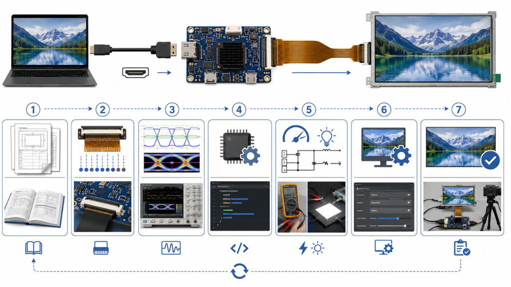
Flusso di lavoro ingegneristico per la verifica della compatibilità del pannello LCD HDMI-to-MIPI
8. Trattare il touch come un'interfaccia separata
La conversione di un segnale video HDMI in MIPI DSI non comporta automaticamente la conversione o l'attivazione dell'input tattile. Un pannello touch capacitivo può utilizzare USB, I2C o un'altra connessione, mentre il suo controller potrebbe richiedere il supporto di driver e firmware lato host.
MIPI mantiene inoltre una serie separata di specifiche per l'integrazione tattile, dimostrando che la trasmissione video e l'input tattile sono funzioni di sistema distinte.[5]
Per un progetto con sorgente HDMI, verificare:
Il modello del controller touch
L'interfaccia touch, ad esempio USB o I2C
Il supporto driver host richiesto
I requisiti di alimentazione del touch
La mappatura delle coordinate e l'orientamento dello schermo
Se la scheda controller espone o elabora il segnale touch
Per maggiori dettagli sui percorsi separati del video HDMI e del touch, consultare la guida di RJY Display su Integrazione touch Android e HDMI.
Revisione della compatibilità per la scheda RJY-HDMI-MIPI-V1
La pagina prodotto attuale di RJY Display identifica la scheda controller RJY-HDMI-MIPI-V1 come un convertitore HDMI-to-MIPI basato sul chip principale LT6911C. La configurazione pubblicata descrive una connessione LCD MIPI a quattro canali, un connettore FPC da 40 pin con passo 0,5 mm e il supporto per risoluzioni fino a 1920 × 1200.[6]
Elemento della scheda pubblicato
Cosa stabilisce
Cosa richiede ancora conferma
Funzione HDMI-to-MIPI
La scheda funge da ponte tra una sorgente HDMI e un'uscita LCD MIPI
Modalità di ingresso HDMI supportate e firmware specifico per il pannello
Uscita LCD MIPI a quattro canali
La configurazione di uscita dichiarata utilizza quattro canali dati MIPI
Frequenza del canale del pannello, ordine dei canali, polarità e modalità
Connettore FPC da 40 pin con passo 0,5 mm
Il formato fisico del connettore
Compatibilità pin-to-pin completa e orientamento del FPC
Risoluzione massima fino a 1920 × 1200
Un limite di risoluzione pubblicato
Temporizzazione esatta della risoluzione, frequenza di aggiornamento e formato pixel
Supporto retroilluminazione LED
La scheda include funzionalità relative alla retroilluminazione
Compatibilità con la stringa LED effettiva del pannello e i requisiti di dimmerazione
Queste specifiche sono utili per una selezione iniziale, ma un pannello non dovrebbe essere dichiarato compatibile finché non siano stati esaminati il suo datasheet, la definizione dei pin, le informazioni di inizializzazione, la temporizzazione e i requisiti di alimentazione.
Esempio: un pannello da 800 × 1280, a quattro linee, 40 pin è compatibile?
Non sono disponibili informazioni sufficienti per rispondere basandosi solo su queste tre specifiche.
Il pannello supera una selezione iniziale perché la sua risoluzione è inferiore al massimo pubblicato della scheda e il numero di canali e il formato del connettore dichiarati appaiono pertinenti. Tuttavia, la conferma ingegneristica richiede ancora:
Il modello completo del pannello e il datasheet
La definizione esatta dei 40 pin
L'orientamento dei contatti del FPC
Temporizzazione orizzontale e verticale
La frequenza di aggiornamento richiesta
Il formato pixel e la velocità dati per canale
Il requisito di modalità video o comando
Il circuito integrato del driver e la sequenza di inizializzazione
I rail di alimentazione logici e di polarizzazione
La sequenza di reset e alimentazione
Tensione, corrente, abilitazione e metodo di dimmerazione della retroilluminazione
Interfaccia del controller touch, se il touch è incluso
La compatibilità dovrebbe essere confermata rispetto a questi elementi prima di collegare una scheda campione al pannello.
Flusso di lavoro consigliato per l'abbinamento pannello HDMI-to-MIPI
Acquisire il datasheet originale del pannello. Un elenco del rivenditore o una fotografia del connettore non sono sufficienti.
Confermare l'interfaccia e la modalità operativa DSI. Identificare il numero di canali, il formato pixel, la modalità video o comando e i requisiti di inizializzazione.
Confrontare la definizione dei pin del FPC. Verificare ogni segnale e pin di alimentazione, incluso l'orientamento del connettore.
Esaminare la temporizzazione e la larghezza di banda. Confrontare risoluzione, frequenza di aggiornamento, clock pixel, blanking, frequenza del canale e limiti del bridge.
Esaminare i circuiti di alimentazione e retroilluminazione. Confermare i rail logici, i rail di polarizzazione, la sequenza, il reset, la corrente LED e la dimmerazione.
Confermare la disponibilità del firmware. Determinare se il firmware esistente supporta il pannello o deve essere adattato.
Verificare la modalità della sorgente HDMI. Confermare che la sorgente possa produrre la temporizzazione di ingresso richiesta.
Testare una combinazione campione controllata. Utilizzare insieme il pannello, la scheda, il cavo, il firmware e la configurazione di alimentazione confermati.
Alimentazione della scheda, tensioni dei rail del pannello, segnali di abilitazione, orientamento del connettore e stato di protezione
Retroilluminazione accesa ma nessuna immagine
Inizializzazione DSI, sequenza di reset, temporizzazione, configurazione delle linee, firmware e abilitazione del pannello
Immagine spostata o che scorre
Temporizzazione orizzontale e verticale, clock dei pixel, impostazioni di sincronizzazione e frequenza di aggiornamento
Colori errati
Formato pixel, ordine dei colori, profondità di bit e configurazione del driver IC
Artefatti intermittenti
Velocità delle linee, integrità del segnale, qualità del cavo FPC, messa a terra, stabilità dell'alimentazione e margine di temporizzazione
Il video funziona ma il tocco no
Interfaccia touch, driver host, connessione USB o I2C, alimentazione, mappatura e orientamento
Immagine corretta ma con orientamento sbagliato
Rotazione della sorgente, configurazione della scansione del pannello, comandi di inizializzazione e capacità del firmware del bridge
Cosa inviare per una revisione tecnica della compatibilità
Fornire documentazione completa prima del campionamento riduce tentativi ed errori non necessari. Preparare:
Numero modello completo del pannello LCD
Scheda tecnica originale del pannello
Tabella delle temporizzazioni del pannello
Definizione dei pin del cavo FPC e disegno del connettore
Modello del driver IC
File dei comandi di inizializzazione o codice di riferimento
Specifiche della retroilluminazione
Informazioni sul pannello touch e sul controller touch
Dispositivo sorgente HDMI e modalità di uscita disponibili
Orientamento dello schermo richiesto
Applicazione target e ambiente operativo
Quantità di campioni e domanda di produzione prevista
Se la scheda tecnica originale o la sequenza di inizializzazione non sono disponibili, identificare tale limitazione all'inizio della revisione. Una fotografia e la risoluzione nominale da sole sono raramente sufficienti per un adattamento affidabile del pannello MIPI.
Richiedere una revisione della compatibilità HDMI-to-MIPI
RJY Display può revisionare il tuo pannello LCD MIPI, la sorgente HDMI, il connettore, la temporizzazione, la retroilluminazione, il tocco e i requisiti del firmware prima della selezione del campione. La compatibilità viene valutata per la configurazione effettiva del pannello e della scheda controller, non dedotta solo dalle dimensioni del connettore.
Lo stesso connettore a 40 pin significa che un pannello LCD è compatibile?
No. Lo stesso numero di pin e lo stesso passo del connettore non garantiscono la stessa definizione dei pin. Alimentazione, massa, linee MIPI, reset, retroilluminazione, tocco e segnali di controllo devono essere confrontati pin per pin prima della connessione.
Una scheda HDMI-to-MIPI a quattro linee può pilotare un pannello MIPI a due linee?
Solo se l'hardware e il firmware del bridge supportano la configurazione a due linee del pannello, la temporizzazione, il formato pixel e la velocità delle linee richiesta. La sola capacità a quattro linee non conferma la compatibilità a due linee.
La compatibilità è confermata se la risoluzione del pannello è inferiore alla risoluzione massima della scheda?
No. La risoluzione massima è solo un limite iniziale di capacità. Anche il clock esatto dei pixel, gli intervalli di blanking, la frequenza di aggiornamento, la modalità DSI, il formato pixel, la velocità delle linee, la sequenza di inizializzazione e il firmware devono corrispondere.
Una scheda controller HDMI-to-MIPI supporta automaticamente l'input touchscreen?
No. Il tocco utilizza normalmente un controller separato e un percorso di comunicazione come USB o I2C. L'interfaccia touch, il driver host, l'alimentazione, la mappatura delle coordinate e l'orientamento devono essere revisionati separatamente.
Quali documenti sono necessari per confermare la compatibilità del LCD MIPI?
La revisione dovrebbe includere la scheda tecnica originale del pannello, la definizione completa dei pin del cavo FPC, la tabella delle temporizzazioni, il driver IC, i comandi di inizializzazione, la sequenza di alimentazione, le specifiche della retroilluminazione, i dettagli del controller touch e le informazioni sulla sorgente HDMI.
Un pannello MIPI a quattro linee 800 × 1280 può essere approvato in base alla sua risoluzione e al numero di linee?
No. Queste specifiche sono utili per una selezione iniziale, ma l'approvazione richiede ancora il pinout del pannello, la temporizzazione, la modalità operativa, la sequenza di inizializzazione, i rail di alimentazione, i requisiti di retroilluminazione, il supporto del firmware e la configurazione dell'uscita della sorgente.
Condividi le dimensioni del display, la risoluzione, l'interfaccia, la luminosità, i requisiti tattili, i requisiti della scheda controller e l'ambiente applicativo.