Enfrentando um gargalo no seu Projeto de Display Incorporado?
Não deixe que a integração complexa ou problemas na cadeia de abastecimento atrasem o seu tempo de colocação no mercado. Marque uma consulta gratuita com a equipa de especialistas da RJY para apoio personalizado em design e fabrico.
Como Escolher um Display LCD de Barra para uma IHM Embarcada
Publicado:
Leitura de 14 minutos
Atualizado:
Um display LCD em barra pode posicionar informações de status, controles, navegação ou dados de equipamento dentro de um espaço que não pode acomodar uma tela retangular convencional. No entanto, seu formato incomum altera a forma como o display deve ser selecionado e integrado.
Apenas o tamanho diagonal não é suficiente. Uma equipe de engenharia também precisa das dimensões da área ativa, matriz de pixels, temporização nativa, contorno do módulo, interface, estrutura de toque, requisitos de retroiluminação, direção do FPC e uma plataforma host capaz de renderizar a interface de usuário pretendida.
O processo de seleção correto, portanto, começa com a janela física do produto e a carga de trabalho da IU. Ele não começa escolhendo o painel mais longo ou de maior resolução em um catálogo.
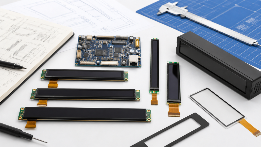
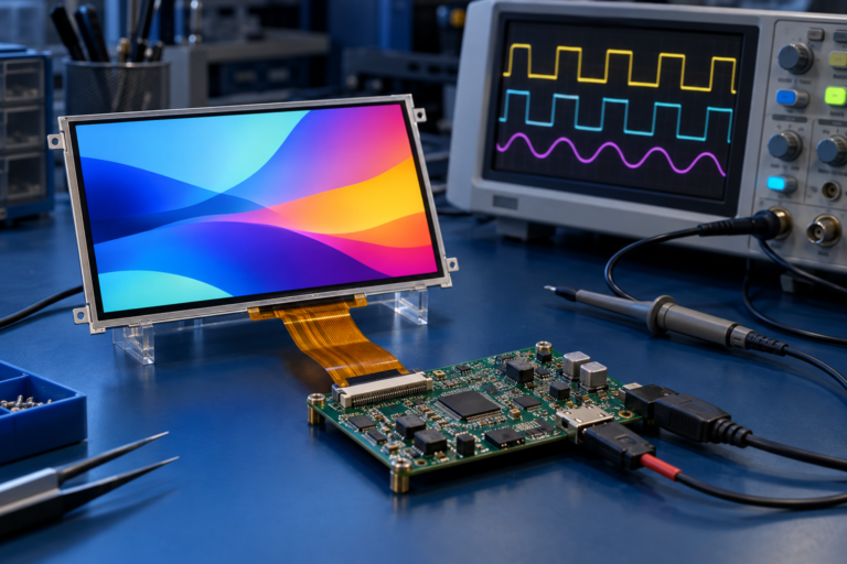
Módulos de display LCD em barra sendo avaliados com uma placa de controle, painel de toque, FPC e invólucro do equipamento
O que é um Display LCD em Barra?
Um LCD em barra é um módulo TFT LCD com uma área de display substancialmente alongada. Também pode ser descrito como um LCD tipo barra, tira, esticado ou ultra-largo. Esses nomes descrevem a forma geral, mas não definem um padrão elétrico ou mecânico intercambiável.
Um display em barra pode ser montado na horizontal ou na vertical. A orientação do produto não corresponde necessariamente à orientação nativa de pixels do painel, à direção de saída do FPC ou à configuração de inicialização. Esses detalhes devem ser verificados na ficha técnica atual do painel e no desenho mecânico.
A categoria atual de displays em barra da RJY Display mostra seis linhas de produtos públicos que abrangem diferentes tamanhos físicos e configurações de interface.[1] Cada modelo deve ser avaliado como um módulo individual, e não como uma versão escalada de outro display em barra.
Comece pelo Espaço Disponível, Não pela Diagonal
Dois displays com medidas diagonais semelhantes podem ter larguras e alturas muito diferentes quando suas proporções de tela diferem. A diagonal também não informa nada sobre a posição da área ativa, a moldura ao redor dela, a saída do FPC ou os componentes na parte traseira do módulo.
Defina as seguintes dimensões antes de comparar produtos:
Dimensão
O que Descreve
Por Que Isso Importa
Área ativa
A área física na qual os pixels produzem uma imagem
Determina a tela visual real e a densidade de pixels
Área de visualização
A abertura através da qual a imagem deve ser visualizada
Deve estar alinhada com o bezel, vidro de cobertura e invólucro
Contorno do módulo
A largura, altura e espessura completas do conjunto do display
Controla o ajuste, a folga de montagem e o acesso para montagem
Contorno do vidro de cobertura
As dimensões externas da lente quando o vidro de cobertura está incluído
Afeta o invólucro frontal, a área de adesivo e a borda cosmética
Envelope do FPC
A localização, comprimento, direção e área de curvatura do cabo
Controla o posicionamento da PCB e evita tensão no cabo
Área de exclusão de componentes
Espaço necessário ao redor do driver, conector, moldura ou componentes traseiros
Previne interferência com suportes, fixadores e a PCB principal
Solicite o desenho dimensionado em vez de estimar esses valores a partir de uma fotografia do produto. O desenho deve ser revisado juntamente com o modelo do invólucro antes que qualquer um dos componentes seja liberado para ferramental.
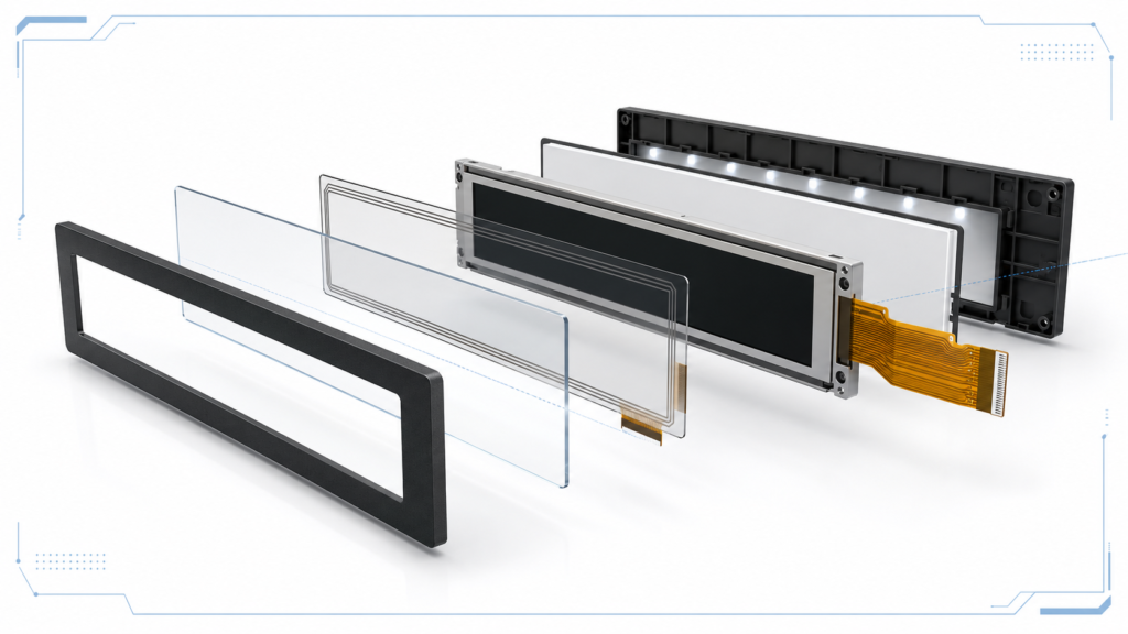
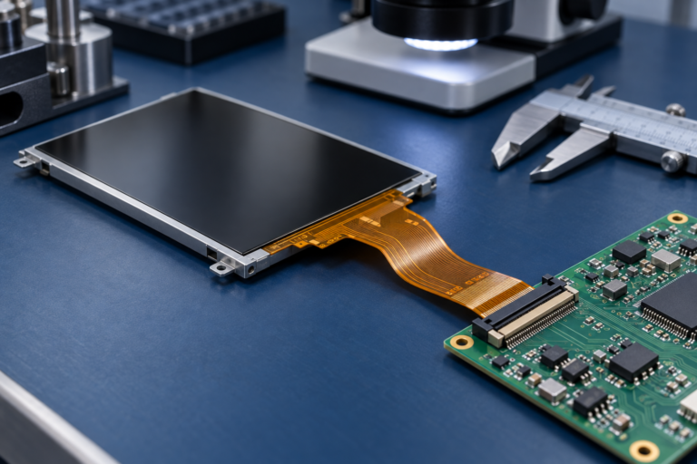
Conjunto de LCD em barra mostrando área ativa, contorno do módulo, camada de toque, vidro de cobertura, retroiluminação e FPC
Corresponda a Matriz de Pixels à Interface do Usuário
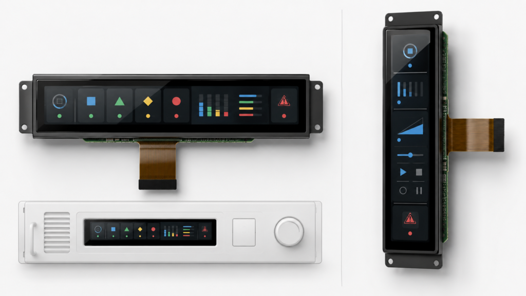
Displays em barra frequentemente utilizam matrizes de pixels que são muito mais longas em uma direção do que na outra. Isso é útil para linhas do tempo, status de equipamentos, navegação, controles agrupados, informações de mídia, interfaces de eletrodomésticos ou painéis secundários, mas a aplicação deve ser projetada para a tela real.
Rotacionar uma IU convencional não a torna automaticamente adequada para uma tela estreita. Um design criado para uma proporção de tela padrão de desktop ou tablet pode produzir diálogos cortados, texto ilegível, margens excessivamente grandes ou controles que não podem ser alcançados sem rolagem excessiva.
Requisito da IU
Implicação no Display
Pergunta a Resolver
Status de equipamento em uma linha
Beneficia-se de uma tela horizontal longa
O texto necessário permanece legível na distância de visualização pretendida?
Faixa de controle vertical
Requer um layout retrato estreito
Os controles, avisos e alvos de toque caberão na dimensão curta?
Vários campos de dados ao vivo
Requer resolução e desempenho de renderização suficientes
Quais valores devem permanecer visíveis simultaneamente?
Animação ou vídeo
Aumenta os requisitos de gráficos, memória, largura de banda e software
O host consegue sustentar a taxa de atualização necessária na resolução nativa?
Múltiplos idiomas
Pode exigir áreas de texto flexíveis e fontes maiores
O texto traduzido mais longo foi testado na tela real?
Crie telas de interface do usuário representativas nas dimensões nativas de pixel do painel antes de aprovar a exibição. Inclua alarmes, strings traduzidas longas, diálogos de manutenção, telas de inicialização, estados de erro e qualquer teclado na tela exigido pelo produto.
Como Escolher um Display LCD em Barra para uma IHM Embarcada 5
Verifique a Proporção de Tela, a Densidade de Pixels e a Distância de Visualização
A proporção de aspecto descreve a relação entre as dimensões longa e curta da imagem. Deve ser calculada a partir da matriz de pixels ativos e considerada em conjunto com a área ativa física.
A densidade de pixels pode ajudar a comparar o tamanho do texto e dos gráficos entre painéis candidatos, mas um valor de PPI mais alto não é automaticamente melhor. A densidade apropriada depende da distância de visualização, renderização de fontes, escala da interface do usuário, capacidade do processador e da quantidade de informações que devem ser exibidas.
Guia de interface LCD da Calculadora de parâmetros de LCD TFT pode fornecer uma estimativa inicial da proporção de aspecto, passo de pixel e PPI. O resultado deve então ser verificado com a arte da interface do usuário em escala real e, quando possível, com uma amostra física.
Não compare painéis apenas pela contagem total de pixels. Uma matriz longa e estreita e uma matriz retangular convencional podem conter um número semelhante de pixels, criando layouts totalmente diferentes.
Confirme o Temporização Nativa do Display
A resolução identifica apenas os pixels ativos. Um controlador de exibição também precisa da temporização nativa completa, incluindo clock de pixel, sincronização horizontal e vertical, front porch, back porch, taxa de atualização, polaridade do sinal e formato de pixel, quando aplicável.
A nota de aplicação de exibição MIPI DSI da NXP mostra que a integração do painel inclui alimentação, reset, GPIO do backlight, parâmetros de temporização, polaridade do sinal, clock de pixel, configuração D-PHY e o driver do painel — não apenas a resolução ativa.[2]
Item de Temporização
Por Que Deve Ser Confirmado
Sintoma Possível Quando Incorreto
Largura e altura ativas
Define a matriz de imagem nativa
Imagem cortada, em branco ou não suportada
Clock de pixel
Controla a taxa na qual os dados de pixel são transmitidos
Imagem instável ou falha na sincronização
Porches horizontais e verticais
Definem os intervalos de blanking ao redor da imagem ativa
Imagem deslocada, rolante ou distorcida
Taxa de atualização
Afeta a largura de banda e o comportamento de atualização visual
Cintilação, artefatos ou temporização não suportada
Formato de pixel
Define o empacotamento de dados de cor
Cores erradas ou nenhuma imagem utilizável
Sequência de inicialização
Configura o driver do painel antes da operação normal
Backlight aceso sem imagem
Um host que suporta uma resolução máxima maior não é automaticamente compatível com cada temporização de painel de barra menor. O modo exato deve estar disponível no host, implementado no BSP ou gerado por uma configuração adequada da placa controladora.
Selecione a Interface como Parte da Arquitetura do Sistema
A interface impressa em uma página de produto é um item de triagem inicial. A compatibilidade ainda depende da configuração elétrica, temporização, definição de pinos, firmware e implementação do conector.
Rota da Interface
Adequação Potencial ao Projeto
Itens a Confirmar
SPI
Interfaces compactas baseadas em MCU com uma carga de atualização adequada
Modo de barramento, formato de pixel, inicialização, taxa de atualização prática e suporte ao driver
RGB
Conexão paralela direta a um controlador de exibição compatível
Largura de dados, tensão, temporização, sincronização, roteamento de PCB e pinagem do FPC
MIPI DSI
Sistemas embarcados compactos usando um processador de aplicação ou bridge suportado
Número de lanes, taxa de lanes, modo de operação, temporização, inicialização, sequência de alimentação e firmware
LVDS
Sistemas embarcados suportados e configurações de exibição maiores
Configuração de canais, mapeamento, tensão, temporização, cabo, conector e backlight
HDMI ou outra fonte de vídeo externa
PC, computador de placa única ou arquitetura de controlador de exibição separada
Modo de saída nativa, escalonamento, rotação, compatibilidade com bridge, comportamento EDID e caminho de toque separado
MIPI DSI é uma interface host-para-exibição que suporta comunicação de alta velocidade entre um processador e um módulo de exibição.[3] Essa definição não torna cada painel MIPI compatível com cada host MIPI. Configuração de lanes, temporização, modo de operação, inicialização, pinagem, alimentação e firmware permanecem específicos do painel.
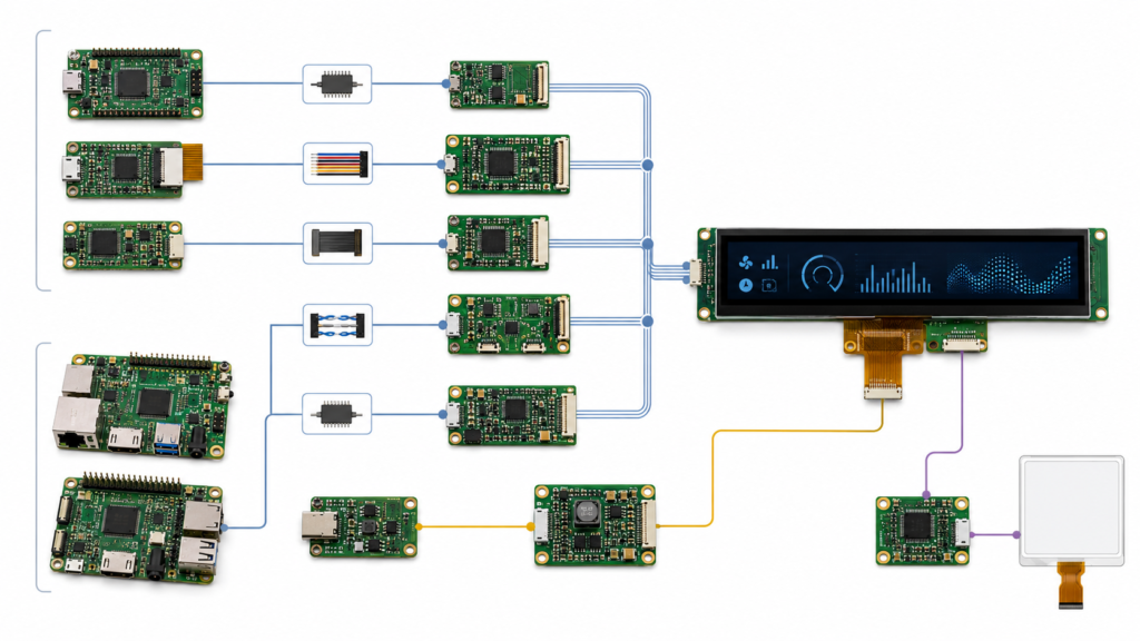
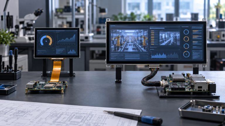
Opções de arquitetura de interface, toque e backlight para uma exibição LCD de barra
Não Presuma que o Host Irá Escalar ou Girar a Imagem
Um projeto comum de exibição de barra começa com um host que normalmente gera resoluções de monitor padrão. A equipe então espera que uma placa bridge ou sistema operacional corte, estique, gire ou escale essa imagem para a temporização nativa do painel de barra.
Essas funções nunca devem ser assumidas. Dependendo da arquitetura, a rotação ou o escalonamento podem ser realizados pelo aplicativo, framework gráfico, sistema operacional, controlador de exibição, firmware da bridge ou driver do painel. Algumas configurações podem suportar apenas um modo de entrada definido e uma saída de painel definida.
Para sistemas baseados em Android, a documentação do AOSP reconhece exibições que variam de proporções de aspecto longas e finas a formatos quadrados, mas aplicativos e implementações de dispositivos ainda precisam da configuração apropriada de proporção de aspecto, tamanho, rotação, densidade e escalonamento.[4]
Antes de selecionar o painel, confirme:
A largura e altura nativas do framebuffer
Se a interface do usuário é renderizada nativamente ou escalada
Se o sistema usa temporização retrato ou paisagem
Onde ocorre a rotação de 90 graus ou 270 graus
Se a placa bridge suporta os modos de entrada e saída necessários
Como os gráficos de inicialização, diagnósticos e telas de recuperação são exibidos
Se a exibição permanece utilizável antes do aplicativo principal iniciar
Se o projeto utilizar uma fonte HDMI com um painel MIPI, siga uma revisão de compatibilidade específica do painel, em vez de tratar o bridge como um adaptador passivo. A RJY Display fornece a sequência detalhada de revisão no guia de compatibilidade da placa controladora HDMI-para-MIPI. Um LCD em barra pode ser combinado com touch capacitivo quando uma configuração adequada de display-touch estiver disponível, mas o touch não é transportado automaticamente pela interface de vídeo do display. O controlador de touch normalmente possui seu próprio caminho de alimentação, reset, interrupção e comunicação.
Trate o Toque como um Subsistema Separado
O projeto deve coordenar a área ativa do touch, o vidro de cobertura, o controlador, o FPC, a interface do host, o driver, o sistema de coordenadas e a orientação do display.
A documentação de dispositivos touch do Android explica que as coordenadas brutas do touch são mapeadas para os pixels do display e que a entrada touch sensível à orientação pode ser remapeada quando o display gira.
Isso é particularmente importante em um display longo e estreito, pois uma troca ou rotação incorreta de eixo pode posicionar a entrada longe do controle visível.[5] A validação do touch deve incluir:.
Precisão das coordenadas em toda a área ativa
Comportamento nas bordas e cantos
Mapeamento correto após a rotação do display
Operação com o vidro de cobertura final e a pilha de adesão
Comportamento do touch durante o sono e despertar do display
Exposição a ruído elétrico da fonte de alimentação, backlight, motor ou outros equipamentos
Reconhecimento pelo sistema operacional e aplicativo finais
Uma imagem de display funcionando corretamente não prova que o sistema de touch está integrado corretamente.
O brilho deve ser selecionado para o ambiente de visualização pretendido, em vez de maximizado sem uma revisão do sistema. O requisito apropriado depende da luz ambiente, material de cobertura, ângulo de visão, distância do usuário, design do invólucro, orçamento de energia e condições térmicas.
Defina os Requisitos de Brilho e Retroiluminação a Partir do Ambiente
O backlight também deve ser compatível eletricamente. Confirme seus requisitos de entrada, configuração de LED, controle de corrente, lógica de habilitação, método de dimming e quaisquer restrições térmicas. Uma placa controladora que suporta uma configuração de backlight pode não suportar outra sem alterações no circuito.
Avalie o conjunto completo no brilho pretendido. O vidro de cobertura, bordas impressas, material de adesão, tratamentos de superfície e a abertura do invólucro podem afetar a aparência do produto final.
Um display em barra pode caber na abertura frontal, mas ainda assim entrar em conflito com a estrutura interna. O quadro traseiro, área do driver, FPC, conector, cauda do touch, componentes do backlight ou raio de curvatura do cabo podem ocupar espaço necessário para a PCB principal ou suportes do invólucro.
Revise a Integração Mecânica e o Roteamento do FPC
A revisão mecânica deve cobrir:.
Item Mecânico
Pergunta de Revisão
O conjunto completo cabe com tolerâncias de fabricação realistas?
Contorno do módulo
Alinhamento da área ativa
A imagem visível está centralizada corretamente dentro da abertura do bezel?
Saída do FPC
O cabo consegue alcançar o conector sem dobrar sobre um componente ou borda afiada?
Acesso ao conector
O conector pode ser aberto, fechado, inspecionado e reparado durante a montagem?
Suporte e adesivo
As forças são aplicadas em áreas estruturais aprovadas, em vez do vidro ativo?
O contorno, borda, abertura, área de adesão e pilha de touch correspondem ao invólucro?
Vidro de cobertura
Folga térmica
O display está isolado de fontes de calor locais e tensão mecânica não intencional?
Revise o desenho do display e o CAD do invólucro juntos antes de finalizar a ferramentaria. Mover um conector ou alterar o invólucro após a amostragem pode criar um redesenho mais amplo do que selecionar um módulo mais adequado anteriormente.
Arquitetura.
Escolha entre Acionamento Direto do Painel e uma Placa Controladora
Apropriada Quando
Escopo Principal de Validação
MCU ou processador aciona o LCD diretamente
O host expõe a interface necessária e pode gerar o timing nativo
Pinagem, timing, framebuffer, driver, inicialização, backlight, touch e roteamento da PCB
Placa de computação embarcada aciona o LCD
O produto precisa de um processador de aplicação, sistema operacional, rede ou controle periférico
Implementação da interface em nível de placa, BSP, driver do painel, touch, carga de trabalho da aplicação, energia e mecânica
Bridge de vídeo ou placa controladora LCD
A saída da fonte e a interface do painel diferem
Modo de entrada, timing de saída, escalonamento, rotação, firmware, alimentação do painel, backlight e caminho do touch
Conjunto estilo monitor externo
O projeto se beneficia de conjuntos de display e host separados
Cabos, retenção, identificação de vídeo, caminho de retorno do touch, alimentação, montagem e comportamento de inicialização
A lista de componentes mais curta nem sempre é a arquitetura de menor risco. Uma interface direta pode reduzir o hardware, mas requer controle rigoroso do driver do painel e do design da placa. Um roteamento de placa controladora pode simplificar a conexão do host apenas quando a placa for confirmada para o painel real e o modo de entrada.
A linha de produtos públicos da RJY Display fornece vários pontos de partida para revisão de engenharia:.
Utilize Plataformas de LCD em Barra Existentes como Ponto de Partida
Revisão para layouts de HMI embarcada maiores após a confirmação das especificações atuais
Esses links são pontos de partida para descoberta de produtos, não aprovações de compatibilidade. Solicite a ficha técnica mais recente, desenho mecânico, definição de pinos, tabela de temporização, informações do driver, especificação de toque e requisitos de retroiluminação antes de selecionar uma amostra.
O que Pode ser Personalizado em Torno de um LCD em Barra Existente?
Quando a plataforma LCD principal for adequada, um projeto pode avaliar alterações no módulo existente. O escopo prático pode incluir vidro de cobertura, integração de toque, retroiluminação, FPC, conector ou coordenação de interface, placa controladora, configuração de firmware e estrutura mecânica.
Isso não deve ser interpretado como a capacidade de criar qualquer tamanho arbitrário de display em barra ou matriz de pixels do zero. A viabilidade depende da plataforma LCD disponível, da modificação proposta, da revisão de engenharia e dos requisitos do projeto.
Lista de Verificação para Validação de Amostra de LCD em Barra
Área de Validação
Revisão Mínima
Imagem
Resolução nativa, temporização, orientação, cor, padrões de tela cheia, inicialização, suspensão e ativação
IU
Fluxo de trabalho normal, alarmes, texto longo, localização, animação, telas de erro e estados de inicialização
Tato
Coordenadas, rotação, bordas, vidro de cobertura, exposição a ruídos, gestos e comportamento de ativação
Interface
Configuração de sinal, cabo ou FPC, retenção do conector, firmware e reinicialização repetida
Luz de fundo
Ativação, escurecimento, faixa de brilho utilizada pelo produto, comportamento de energia e temperatura
Montagem mecânica
Alinhamento, suporte, roteamento do FPC, acesso ao conector, ajuste do vidro de cobertura e tolerâncias do invólucro
Operação do sistema
Limites de tensão, interrupção de energia, falha de aplicação, carga periférica e uso de longa duração
A configuração de produção aprovada deve identificar o modelo do LCD, controlador de toque, revisão da placa, firmware ou BSP, cabo, circuito de retroiluminação, versão do aplicativo, vidro de cobertura e invólucro. Uma alteração em qualquer um desses itens pode exigir revalidação parcial.
O que Enviar para uma Revisão de Seleção de LCD em Barra
Uma solicitação de engenharia útil deve incluir:
Produto alvo e ambiente de aplicação
Largura, altura e espessura máximas do módulo
Área visível necessária e orientação da tela
Resolução preferida ou arte da interface do usuário representativa
Processador host, placa de controle, MCU ou fonte de vídeo
Interfaces de display disponíveis e modos de saída
Requisitos de toque e vidro de cobertura
Brilho e condições de visualização
Direção do FPC, posição do conector e desenho do invólucro
Requisitos de sistema operacional, driver e firmware
Quantidade de protótipos, demanda anual esperada e estágio do projeto
Ficha técnica do painel existente ou modelo de referência, se estiver substituindo outro display
Solicite uma Revisão de Compatibilidade de LCD em Barra
A RJY Display pode revisar uma plataforma LCD em barra existente em relação aos seus requisitos de área ativa, resolução, interface, toque, retroiluminação, FPC, placa controladora, firmware, vidro de cobertura e mecânicos.
Um display LCD em barra é um módulo TFT LCD com uma área ativa alongada e matriz de pixels. Também pode ser descrito como um display tipo barra, tira, esticado ou ultra-amplo, mas esses nomes não definem uma interface padrão, temporização, conector ou contorno mecânico.
O tamanho da diagonal é suficiente para escolher um LCD em barra?
Não. Compare a área ativa, área de visualização, contorno do módulo, resolução, proporção de aspecto, espessura, posição do FPC, conector, estrutura de toque e folgas do invólucro. Displays com tamanhos diagonais semelhantes podem ter proporções físicas substancialmente diferentes.
Uma fonte HDMI padrão pode acionar um display LCD em barra?
Somente através de uma configuração confirmada de display ou placa controladora. O modo da fonte HDMI, interface do painel, temporização nativa, redimensionamento, rotação, firmware, energia, retroiluminação e caminho de toque devem ser verificados para o painel real.
Qual interface é melhor para um LCD em barra?
Não existe uma única interface melhor. SPI, RGB, MIPI DSI, LVDS e rotas de placa controladora atendem a diferentes processadores, resoluções, requisitos de atualização, arranjos de cabo e plataformas de software. Escolha a interface suportada tanto pela implementação real do host quanto pelo painel selecionado.
Um display LCD em barra pode incluir toque capacitivo?
Pode, quando uma configuração de toque adequada estiver disponível para o módulo selecionado. A área ativa de toque, vidro de cobertura, controlador, FPC, interface do host, driver, mapeamento de coordenadas, rotação e ambiente operacional devem ser revisados separadamente da interface de vídeo do display.
Quais informações são necessárias para uma cotação de LCD em barra?
Forneça a aplicação, envelope mecânico máximo, área visível, resolução ou arte da interface do usuário, placa host, interface, requisitos de toque e vidro de cobertura, brilho e ambiente, restrições do FPC, necessidades de firmware, quantidade de protótipos, demanda anual esperada e desenhos ou fichas técnicas disponíveis.