Столкнулись с трудностями в проекте встраиваемого дисплея?
Не позволяйте сложной интеграции или проблемам цепочки поставок замедлить ваш выход на рынок. Забронируйте бесплатную консультацию с экспертной командой RJY для получения индивидуальной поддержки в проектировании и производстве.
Как выбрать ЖК-дисплей для бара в составе встраиваемого человеко-машинного интерфейса (HMI)
Published:
14 минут чтения
Updated:
Барный ЖК-дисплей может размещать информацию о состоянии, элементы управления, навигацию или данные оборудования в пространстве, которое не может вместить обычный прямоугольный экран. Однако его необычная форма изменяет подход к выбору и интеграции дисплея.
Одной лишь диагонали недостаточно. Инженерной группе также необходимы размеры активной области, матрица пикселей, собственные временные характеристики, контур модуля, интерфейс, сенсорная структура, требования к подсветке, направление гибкого печатного кабеля (FPC) и хост-платформа, способная отображать предполагаемый пользовательский интерфейс.
Таким образом, правильный процесс выбора начинается с физического окна продукта и нагрузки пользовательского интерфейса. Он не начинается с выбора самой длинной панели или панели с самым высоким разрешением в каталоге.
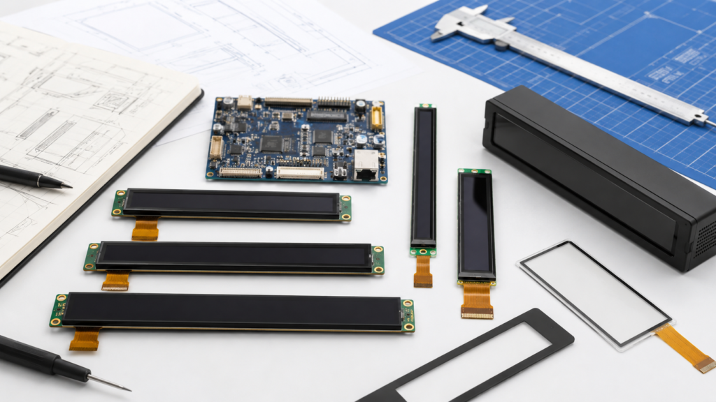
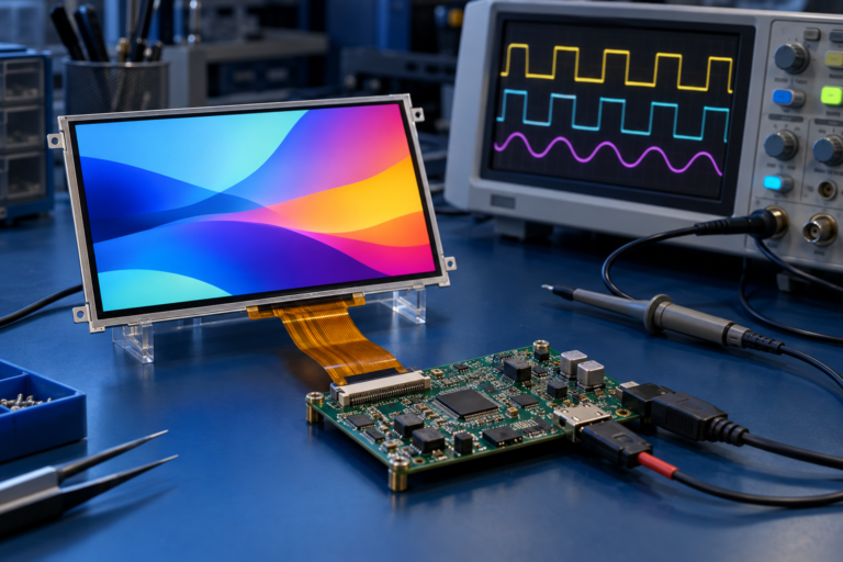
Модули барных ЖК-дисплеев, оцениваемые совместно с контроллерной платой, сенсорной панелью, гибким печатным кабелем (FPC) и корпусом оборудования
Что такое барный ЖК-дисплей?
Барный ЖК-дисплей — это TFT ЖК-модуль с существенно вытянутой областью отображения. Его также могут называть барным, полосовым, растянутым или сверхшироким ЖК-дисплеем. Эти названия описывают общую форму, но не определяют взаимозаменяемый электрический или механический стандарт.
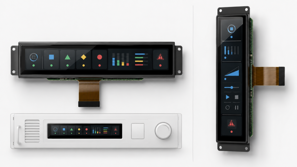
Барный дисплей может быть установлен горизонтально или вертикально. Ориентация продукта не обязательно соответствует собственной ориентации пикселей панели, направлению выхода гибкого печатного кабеля (FPC) или конфигурации инициализации. Эти детали необходимо проверять по актуальному техническому описанию панели и механическому чертежу.
Текущий Категория барных дисплеев Показывает шесть общедоступных продуктовых линеек, охватывающих различные физические размеры и конфигурации интерфейсов.[1] Каждую модель следует оценивать как отдельный модуль, а не как масштабированную версию другого барного дисплея.
Начинайте с доступного пространства, а не с диагонали
Два дисплея с одинаковыми показателями диагонали могут иметь совершенно разные ширину и высоту при различии в соотношении сторон. Диагональ также ничего не говорит о положении активной области, рамке вокруг нее, выходе гибкого печатного кабеля (FPC) или компонентах на задней стороне модуля.
Определите следующие размеры перед сравнением продуктов:
Измерение
Что описывает
Почему это важно
Активная область
Физическая область, в которой пиксели формируют изображение
Определяет фактический визуальный холст и плотность пикселей
Область обзора
Отверстие, через которое предполагается просматривать изображение
Должно совпадать с рамкой, защитным стеклом и корпусом
Контур модуля
Полная ширина, высота и толщина дисплейного узла
Определяет посадку, монтажные зазоры и доступ для сборки
Контур защитного стекла
Внешние размеры линзы при наличии защитного стекла
Влияет на передний корпус, область нанесения клея и декоративную рамку
Зона гибкого печатного кабеля (FPC)
Расположение, длина, направление и область изгиба кабеля
Определяет размещение печатной платы (PCB) и предотвращает нагрузку на кабель
Запретная зона для компонентов
Пространство, необходимое вокруг драйвера, разъема, рамки или задних компонентов
Предотвращает помехи для опор, крепежных элементов и основной печатной платы (PCB)
Запросите чертеж с размерами, а не оценивайте эти значения по фотографии продукта. Чертеж следует рассматривать совместно с моделью корпуса до того, как любой из компонентов будет передан в производство оснастки.
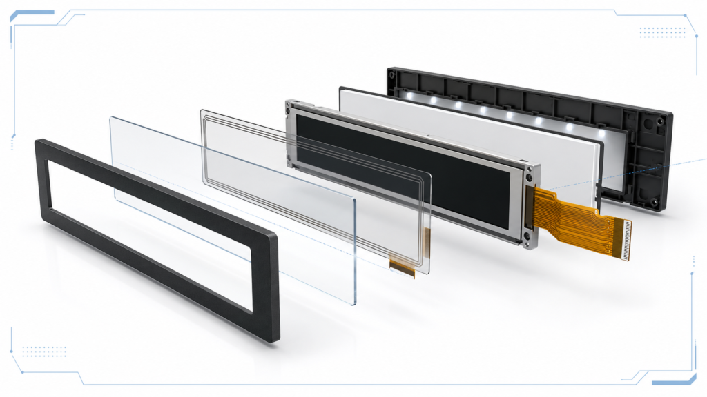
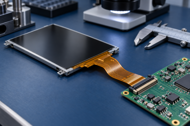
Сборка барного ЖК-дисплея, показывающая активную область, контур модуля, сенсорный слой, защитное стекло, подсветку и гибкий печатный кабель (FPC)
Согласуйте матрицу пикселей с пользовательским интерфейсом
Барные дисплеи часто используют матрицы пикселей, которые значительно длиннее в одном направлении, чем в другом. Это полезно для временных шкал, статуса оборудования, навигации, сгруппированных элементов управления, медиаинформации, интерфейсов бытовой техники или дополнительных приборных панелей, но приложение должно быть разработано для фактического холста.
Поворот обычного пользовательского интерфейса автоматически не делает его подходящим для узкого экрана. Дизайн, созданный для стандартного соотношения сторон настольного компьютера или планшета, может привести к обрезанным диалоговым окнам, нечитаемому тексту, чрезмерно большим полям или элементам управления, до которых невозможно добраться без чрезмерной прокрутки.
Требование к пользовательскому интерфейсу
Влияние на дисплей
Вопрос для решения
Однострочный статус оборудования
Выигрывает от длинного горизонтального холста
Останется ли требуемый текст читаемым на предполагаемом расстоянии просмотра?
Вертикальная полоса управления
Требует узкой портретной компоновки
Поместятся ли элементы управления, предупреждения и сенсорные цели по короткому измерению?
Несколько полей с данными в реальном времени
Требует достаточного разрешения и производительности рендеринга
Какие значения должны оставаться видимыми одновременно?
Анимация или видео
Увеличивает требования к графике, памяти, пропускной способности и программному обеспечению
Сможет ли хост-система поддерживать требуемую частоту обновления при собственном разрешении?
Несколько языков
Может потребоваться использование гибких текстовых полей и увеличенных шрифтов
Проверялся ли самый длинный переведённый текст на реальном канвасе?
Создайте репрезентативные экраны интерфейса в собственных пиксельных размерах панели перед утверждением дисплея. Включите сигналы тревоги, длинные переведённые строки, диалоги обслуживания, стартовые экраны, состояния ошибок и любую экранную клавиатуру, требуемую продуктом.
Как выбрать столбчатый ЖК-дисплей для встроенного HMI 5
Проверьте соотношение сторон, плотность пикселей и расстояние просмотра
Соотношение сторон описывает взаимосвязь между длинной и короткой сторонами изображения. Оно должно рассчитываться на основе активной матрицы пикселей и рассматриваться совместно с физической активной областью.
Плотность пикселей может помочь сравнить размер текста и графики между кандидатными дисплеями, но более высокое значение PPI не всегда лучше. Соответствующая плотность зависит от расстояния просмотра, рендеринга шрифтов, масштаба интерфейса, производительности процессора и объёма информации, которую необходимо отобразить.
RJY Display’s Калькулятор параметров TFT ЖК-дисплея Может дать предварительную оценку соотношения сторон, шага пикселей и PPI. Затем результат следует проверить с помощью полноразмерного макета интерфейса и, по возможности, физического образца.
Не сравнивайте панели только по общему количеству пикселей. Длинная узкая матрица и обычная прямоугольная матрица могут содержать схожее количество пикселей, но создавать совершенно разные макеты.
Подтвердите собственные временные характеристики дисплея
Разрешение определяет только активные пиксели. Контроллер дисплея также требует полной собственной синхронизации, включая тактовую частоту пикселей, горизонтальную и вертикальную синхронизацию, фронтальный и тыловой пороги, частоту обновления, полярность сигнала и формат пикселей, где это применимо.
Примечание по применению дисплея MIPI DSI от NXP показывает, что интеграция панели включает питание, сброс, GPIO подсветки, параметры синхронизации, полярность сигнала, тактовую частоту пикселей, конфигурацию D-PHY и драйвер панели, а не только активное разрешение.[2]
Параметр синхронизации
Почему его необходимо подтвердить
Возможный симптом при некорректной работе
Активная ширина и высота
Определяет собственную матрицу изображения
Обрезанное, пустое или неподдерживаемое изображение
Тактовая частота пикселей
Управляет скоростью передачи данных пикселей
Нестабильное изображение или сбой синхронизации
Горизонтальные и вертикальные пороги
Определяют интервалы гашения вокруг активного изображения
Смещённое, прокручивающееся или искажённое изображение
Частота обновления
Влияет на пропускную способность и поведение визуального обновления
Мерцание, артефакты или неподдерживаемая синхронизация
Формат пикселей
Определяет упаковку цветовых данных
Неправильные цвета или отсутствие пригодного изображения
Последовательность инициализации
Настраивает драйвер панели перед нормальной работой
Подсветка включена без изображения
Хост, поддерживающий большее максимальное разрешение, не является автоматически совместимым с каждой меньшей синхронизацией панели. Точный режим должен быть доступен от хоста, реализован в BSP или сгенерирован соответствующей конфигурацией платы контроллера.
Выберите интерфейс как часть системной архитектуры
Интерфейс, указанный на странице продукта, является начальным пунктом проверки. Совместимость всё ещё зависит от электрической конфигурации, синхронизации, определения выводов, прошивки и реализации разъёма.
Путь интерфейса
Потенциальное соответствие проекту
Пункты для подтверждения
SPI
Компактные интерфейсы на основе MCU с подходящей нагрузкой обновления
Режим шины, формат пикселей, инициализация, практическая частота обновления и поддержка драйвера
RGB
Прямое параллельное подключение к совместимому контроллеру дисплея
Разрядность данных, напряжение, синхронизация, разводка PCB и распиновка FPC
MIPI DSI
Компактные встраиваемые системы с использованием поддерживаемого прикладного процессора или моста
Количество линий, скорость линий, режим работы, синхронизация, инициализация, последовательность питания и прошивка
LVDS
Поддерживаемые встраиваемые системы и конфигурации больших дисплеев
Конфигурация каналов, отображение, напряжение, синхронизация, кабель, разъём и подсветка
HDMI или другой внешний видеоисточник
ПК, одноплатный компьютер или архитектура с отдельным контроллером дисплея
Собственный выходной режим, масштабирование, поворот, совместимость моста, поведение EDID и отдельный путь сенсора
MIPI DSI — это интерфейс от хоста к дисплею, поддерживающий высокоскоростную связь между процессором и модулем дисплея.[3] Это определение не делает каждую панель MIPI совместимой с каждым хостом MIPI. Конфигурация линий, синхронизация, режим работы, инициализация, распиновка, питание и прошивка остаются специфичными для панели.
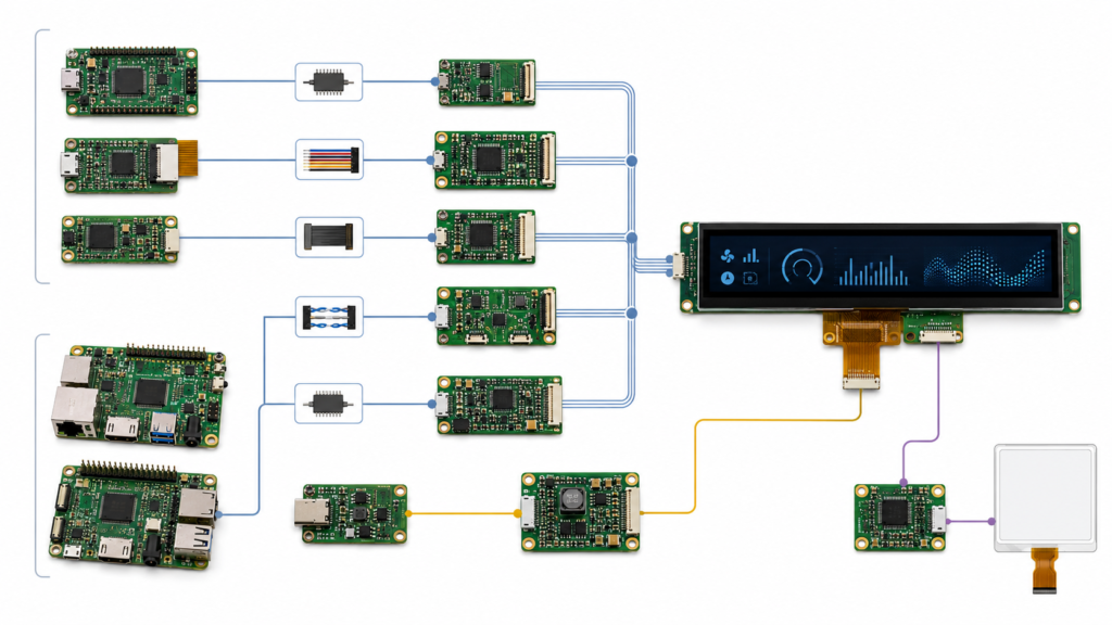
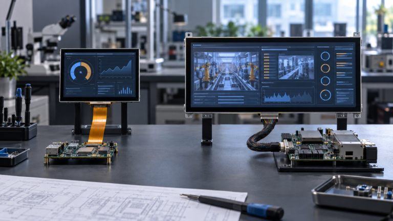
Варианты архитектуры интерфейса, сенсора и подсветки для полосового ЖК-дисплея
Не предполагайте, что хост-система будет масштабировать или поворачивать изображение
Типичный проект полосового дисплея начинается с хоста, который обычно генерирует стандартные разрешения монитора. Затем команда ожидает, что плата моста или операционная система обрежет, растянет, повернёт или масштабирует это изображение в собственную синхронизацию полосовой панели.
Эти функции никогда не следует предполагать. В зависимости от архитектуры поворот или масштабирование могут выполняться приложением, графическим фреймворком, операционной системой, контроллером дисплея, прошивкой моста или драйвером панели. Некоторые конфигурации могут поддерживать только определённый входной режим и определённый выход панели.
Для систем на базе Android документация AOSP признаёт дисплеи от длинных тонких соотношений сторон до квадратных форматов, но приложения и реализации устройств всё равно требуют соответствующей конфигурации соотношения сторон, размера, поворота, плотности и масштабирования.[4]
Перед выбором панели подтвердите:
Собственную ширину и высоту фреймбуфера
Рендерится ли интерфейс нативно или масштабируется
Использует ли система портретную или ландшафтную синхронизацию
Где происходит поворот на 90 или 270 градусов
Поддерживает ли плата моста требуемые входные и выходные режимы
Как отображаются загрузочная графика, диагностика и экраны восстановления
Остаётся ли дисплей работоспособным до запуска основного приложения
Если в конструкции используется источник HDMI с панелью MIPI, выполните проверку совместимости, специфичную для панели, а не рассматривайте мост как пассивный адаптер. Руководство по совместимости плат контроллера HDMI-to-MIPI от RJY Display предоставляет подробную последовательность проверки. Полосовой ЖК-дисплей может быть объединён с ёмкостным сенсором при наличии подходящей конфигурации дисплея и сенсора, но сенсор не передаётся автоматически через видеоинтерфейс дисплея. Контроллер сенсора обычно имеет собственный путь питания, сброса, прерывания и связи.
Рассматривайте сенсорный ввод как отдельную подсистему
Проект должен координировать активную область сенсора, покровное стекло, контроллер, FPC, интерфейс хоста, драйвер, систему координат и ориентацию дисплея.
Документация Android по сенсорным устройствам объясняет, что сырые координаты сенсора отображаются на пиксели дисплея и что ввод сенсора с учётом ориентации может быть переназначен при повороте дисплея.
Android’s touch-device documentation explains that raw touch coordinates are mapped to display pixels and that orientation-aware touch input can be remapped when the display rotates.[5] Это особенно важно на длинном узком дисплее, поскольку неправильная смена осей или поворот могут привести к тому, что ввод будет находиться далеко от видимого элемента управления.
Валидация сенсорного ввода должна включать:
Точность координат по всей активной области
Поведение на краях и в углах
Корректное отображение после поворота дисплея
Работа с финальным покровным стеклом и слоем склейки
Поведение сенсора во время перехода дисплея в режим сна и пробуждения
Воздействие электрических помех от источника питания, подсветки, двигателя или другого оборудования
Распознавание финальной операционной системой и приложением
Корректная работа изображения на дисплее не доказывает правильность интеграции сенсорной системы.
Определите требования к яркости и подсветке исходя из условий эксплуатации
Яркость следует выбирать в соответствии с предполагаемыми условиями просмотра, а не максимизировать без системного анализа. Соответствующее требование зависит от внешнего освещения, материала покровного стекла, угла обзора, расстояния до пользователя, конструкции корпуса, энергетического бюджета и тепловых условий.
Подсветка также должна быть электрически согласована. Подтвердите её входные требования, конфигурацию светодиодов, управление током, логику включения, метод регулировки яркости и любые тепловые ограничения. Контроллерная плата, поддерживающая одну конфигурацию подсветки, может не поддерживать другую без изменений в схеме.
Оценивайте полную сборку при предполагаемой яркости. Покровное стекло, печатные рамки, материал склейки, обработка поверхности и отверстие корпуса могут повлиять на внешний вид готового изделия.
Проанализируйте механическую интеграцию и трассировку гибкого печатного кабеля (FPC)
Панельный дисплей может соответствовать переднему отверстию, но при этом конфликтовать с внутренней конструкцией. Задняя рамка, область драйвера, гибкий печатный кабель (FPC), разъём, сенсорный шлейф, компоненты подсветки или радиус изгиба кабеля могут занимать пространство, необходимое для основной печатной платы или опор корпуса.
Механическая проверка должна охватывать:
Механический элемент
Вопрос для проверки
Контур модуля
Соответствует ли полная сборка реалистичным производственным допускам?
Выравнивание активной области
Правильно ли центрировано видимое изображение в пределах отверстия рамки?
Выход гибкого печатного кабеля (FPC)
Может ли кабель достичь разъёма без перегиба через компонент или острый край?
Доступ к разъёмам
Можно ли открыть, закрыть, проверить и обслужить разъём во время сборки?
Опоры и клей
Прикладываются ли усилия к одобренным конструктивным зонам, а не к активному стеклу?
Покровное стекло
Соответствуют ли контур, рамка, отверстие, область клея и сенсорный стек корпусу?
Тепловой зазор
Изолирован ли дисплей от локальных источников тепла и непреднамеренных механических напряжений?
Проверяйте чертёж дисплея и CAD-модель корпуса вместе до окончательного утверждения оснастки. Перемещение разъёма или изменение корпуса после получения образцов может потребовать более масштабной переработки, чем выбор более подходящего модуля на раннем этапе.
Выберите между прямым управлением панелью и использованием контроллерной платы
Архитектура
Применимо, когда
Основная область валидации
Микроконтроллер (MCU) или процессор напрямую управляет ЖК-дисплеем
Хост предоставляет требуемый интерфейс и может генерировать собственные временные параметры
Продукту требуется прикладной процессор, операционная система, сетевые возможности или управление периферией
Реализация интерфейса на уровне платы, пакет поддержки платы (BSP), драйвер панели, сенсор, рабочая нагрузка приложения, питание и механика
Видеомост или плата контроллера ЖК-дисплея
Выход источника и интерфейс панели различаются
Режим входа, выходные временные параметры, масштабирование, поворот, прошивка, питание панели, подсветка и путь сенсора
Внешняя сборка мониторного типа
Проект выигрывает от раздельных сборок дисплея и хоста
Кабели, фиксация, идентификация видео, обратный путь сенсора, питание, монтаж и поведение при запуске
Самый короткий список компонентов не всегда является архитектурой с наименьшим риском. Прямой интерфейс может сократить количество аппаратного обеспечения, но требует тщательного контроля драйвера панели и конструкции платы. Использование контроллерной платы может упростить подключение хоста только в том случае, если плата подтверждена для конкретной панели и режима ввода.
Используйте существующие платформы барных ЖК-дисплеев в качестве отправной точки
Публичный ассортимент продукции RJY Display предоставляет несколько отправных точек для инженерной проверки:
Проверка для более крупных встроенных HMI-компоновок после подтверждения текущих спецификаций
Эти ссылки являются отправными точками для поиска продукта, а не подтверждением совместимости. Запросите последнюю спецификацию, механический чертёж, определение выводов, таблицу временных параметров, информацию о драйвере, спецификацию сенсора и требования к подсветке перед выбором образца.
Что можно адаптировать на основе существующего барного ЖК-дисплея?
Если основная платформа ЖК-дисплея подходит, проект может оценить изменения вокруг существующего модуля. Практическая область может включать покровное стекло, интеграцию сенсора, подсветку, гибкий печатный кабель (FPC), координацию разъёма или интерфейса, контроллерную плату, конфигурацию прошивки и механическую структуру.
Это не следует интерпретировать как возможность создания произвольного размера панельного дисплея или пиксельной матрицы с нуля. Реализуемость зависит от доступной платформы ЖК-дисплея, предлагаемой модификации, инженерной проверки и требований проекта.
Обычный рабочий процесс, сигналы тревоги, длинный текст, локализация, анимация, экраны ошибок и состояния загрузки
Сенсор
Координаты, поворот, края, покровное стекло, воздействие шума, жесты и поведение при пробуждении
Интерфейс
Конфигурация сигнала, кабель или FPC, фиксация разъема, прошивка и повторная перезагрузка
Подсветка
Включение, затемнение, диапазон яркости, используемый продуктом, поведение при питании и температура
Механическая сборка
Выравнивание, поддержка, трассировка FPC, доступ к разъему, посадка покровного стекла и допуски корпуса
Работа системы
Пределы напряжения, прерывание питания, сбой приложения, нагрузка периферии и длительное использование
Утвержденная производственная конфигурация должна определять модель LCD, контроллер сенсорного ввода, ревизию платы, прошивку или BSP, кабель, цепь подсветки, версию приложения, покровное стекло и корпус. Изменение любого из этих элементов может потребовать частичной повторной валидации.
Что отправить для рассмотрения выбора барного ЖК-дисплея
Полезный инженерный запрос должен включать:
Целевой продукт и среда применения
Максимальные ширина, высота и толщина модуля
Требуемая видимая область и ориентация экрана
Предпочтительное разрешение или репрезентативный UI-макет
Главный процессор, управляющая плата, MCU или источник видео
Доступные интерфейсы дисплея и режимы вывода
Требования к сенсорному вводу и покровному стеклу
Яркость и условия просмотра
Направление FPC, положение разъема и чертеж корпуса
Требования к операционной системе, драйверу и прошивке
Количество прототипов, ожидаемый годовой спрос и стадия проекта
Существующий даташит панели или эталонная модель, если заменяется другой дисплей
RJY Display может проверить существующую платформу bar LCD на соответствие вашим требованиям к активной области, разрешению, интерфейсу, сенсорному вводу, подсветке, FPC, контроллерной плате, прошивке, покровному стеклу и механике.
Bar LCD дисплей — это TFT LCD модуль с удлиненной активной областью и матрицей пикселей. Его также можно назвать дисплеем барового типа, полосовым, растянутым или сверхшироким, но эти названия не определяют стандартный интерфейс, тайминг, разъем или механический контур.
Достаточно ли диагонального размера для выбора bar LCD?
Нет. Сравните активную область, область просмотра, контур модуля, разрешение, соотношение сторон, толщину, положение FPC, разъем, сенсорную структуру и зазоры корпуса. Дисплеи с похожими диагональными размерами могут иметь существенно разные физические пропорции.
Может ли стандартный источник HDMI управлять bar LCD дисплеем?
Только через подтвержденную конфигурацию дисплея или контроллерной платы. Режим источника HDMI, интерфейс панели, собственный тайминг, масштабирование, поворот, прошивка, питание, подсветка и сенсорный путь должны быть проверены для фактической панели.
Какой интерфейс лучше всего подходит для bar LCD?
Не существует единственного лучшего интерфейса. SPI, RGB, MIPI DSI, LVDS и маршруты контроллерных плат подходят для разных процессоров, разрешений, требований к обновлению, кабельных схем и программных платформ. Выбирайте интерфейс, поддерживаемый как фактической реализацией хоста, так и выбранной панелью.
Может ли bar LCD дисплей включать емкостный сенсорный ввод?
Может, если для выбранного модуля доступна подходящая конфигурация сенсорного ввода. Активная область сенсора, покровное стекло, контроллер, FPC, интерфейс хоста, драйвер, сопоставление координат, поворот и рабочая среда должны рассматриваться отдельно от видеоинтерфейса дисплея.
Какая информация необходима для котировки bar LCD?
Укажите приложение, максимальный механический конверт, видимую область, разрешение или UI-макет, главную плату, интерфейс, требования к сенсорному вводу и покровному стеклу, яркость и условия окружающей среды, ограничения FPC, потребности в прошивке, количество прототипов, ожидаемый годовой спрос и доступные чертежи или даташиты.