Facing a bottleneck in your Embedded Display Project?
Don’t let complex integration or supply chain issues slow your time-to-market. Book a free consultation with the RJY expert team for tailored design and manufacturing support.

A custom MIPI TFT LCD display project is not completed by selecting a panel with “MIPI” in its interface field. The display module and host must agree on the DSI implementation, lane configuration, native timing, pixel format, initialization commands, power sequence, reset behavior, connector, firmware, backlight, touch system, and mechanical structure.
The word “custom” also needs a practical boundary. For most OEM projects, the controllable route begins with an existing MIPI TFT LCD module. The project can then evaluate changes around that platform, such as cover glass, touchscreen, backlight, FPC, connector coordination, controller board, firmware configuration, and mechanical integration.
This guide explains how to decide whether MIPI DSI fits the product, how to match a panel with the actual host, and what information should be controlled before samples or production tooling are approved.
MIPI DSI is a high-speed serial interface between a host processor and a display module. MIPI Alliance describes it as an interface designed to support display performance while reducing pin count, power consumption, and electromagnetic interference compared with broader parallel connections.[1]
A typical embedded MIPI display system contains more than the DSI cable or FPC:
| System Element | Function | Project Question |
|---|---|---|
| Application processor or MCU | Generates the user interface and framebuffer | Can the actual processor and board generate the panel’s required DSI mode and timing? |
| Display controller | Reads pixel data and generates the display stream | Does it support the resolution, pixel format, refresh requirement, and memory bandwidth? |
| MIPI DSI Host | Packages display data and control traffic for the DSI link | Which lane counts, operating modes, clocks, and packet formats are implemented? |
| D-PHY | Provides the physical clock and data lanes | Can the board generate the required lane rate and electrical configuration? |
| TFT LCD module | Receives the stream and displays the image | What are its native timing, driver IC, initialization, voltage, pinout, and backlight requirements? |
| Panel driver or firmware | Controls power, reset, initialization, timing, sleep, wake, and display state | Is the exact panel supported in the bootloader, kernel, BSP, or MCU firmware? |
| Touch and backlight | Provide user input and illumination | Which separate interfaces, drivers, power circuits, and control signals are required? |
Compatibility must be established across this complete path. A compatible connector shape or matching resolution is not enough.
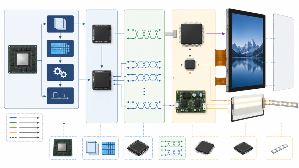
Custom MIPI display is used for several different project scopes. Separating them early prevents an RFQ from being interpreted as a request for an entirely new LCD platform.
| Project Type | Practical Scope | Main Engineering Work |
|---|---|---|
| Standard MIPI module | An existing LCD is used without a physical change | Host compatibility, panel driver, cable, power, backlight, touch, and validation |
| Existing module with surrounding customization | The core LCD remains while touch, cover glass, backlight, FPC, connector coordination, firmware, or mechanics are adapted | Controlled drawings, tooling, samples, firmware, assembly, and system validation |
| MIPI module with controller or bridge board | A board converts or generates the panel’s required DSI output | Input mode, output timing, panel initialization, power, backlight, touch, firmware, and cabling |
| New LCD platform request | The requested size, pixel matrix, or core panel architecture is not available from an existing module | Separate feasibility, development, volume, qualification, and lifecycle review |
RJY Display’s practical customization route starts with an existing display module. Feasible project work can include cover glass, touchscreen, backlight, FPC, interface coordination, controller board, firmware, and mechanical structure. It should not be presented as unrestricted development of any new LCD size or resolution.
MIPI DSI can be a strong fit when the actual processor exposes a supported DSI Host, the product has a short internal display connection, and the engineering team can control the panel driver and system firmware.
It may be appropriate for:
MIPI is not automatically the best choice when:
The correct choice follows the host, display, software, enclosure, cable, performance, and lifecycle requirements. It should not be based on the assumption that MIPI is more modern and therefore universally better.
For a cross-interface overview, see Common Interfaces in LCD Display Modules.
A processor datasheet may show that the SoC family contains a MIPI DSI controller. That does not prove that a particular control board exposes the required lanes, connector, voltages, clocks, GPIOs, firmware, or panel driver.
Before comparing displays, collect:
The host review should be performed at board level. A feature listed for the SoC can be unavailable on the finished board because the pins were not routed, are shared with another function, or are unsupported in the current BSP.
For Android-specific systems, use the detailed guide to matching a TFT LCD module with an Android control board.
A MIPI DSI connection normally contains a clock lane and one or more data lanes. The exact number supported by the panel and the number exposed by the host must be confirmed.
| Lane Item | What to Confirm |
|---|---|
| Host lane capability | Number of data lanes implemented on the actual board and supported by its software |
| Panel lane requirement | Supported or required lane count in the current panel datasheet |
| Lane ordering | Clock and data-lane assignment between the host connector and panel FPC |
| Polarity handling | Whether the implementation and firmware permit any required lane-polarity configuration |
| Virtual channel | The virtual-channel configuration expected by the host and peripheral |
| Connector and FPC | Pin definition, contact orientation, pitch, ground placement, and controlled routing |
Linux’s MIPI DSI device-tree documentation represents the DSI Host and its attached peripherals as a bus, illustrating that the panel is a configured peripheral rather than a passive group of differential wires.[4]
An adapter FPC can change physical pin routing, but it cannot create missing DSI lanes or correct an unsupported DSI mode, lane rate, timing, or firmware implementation.
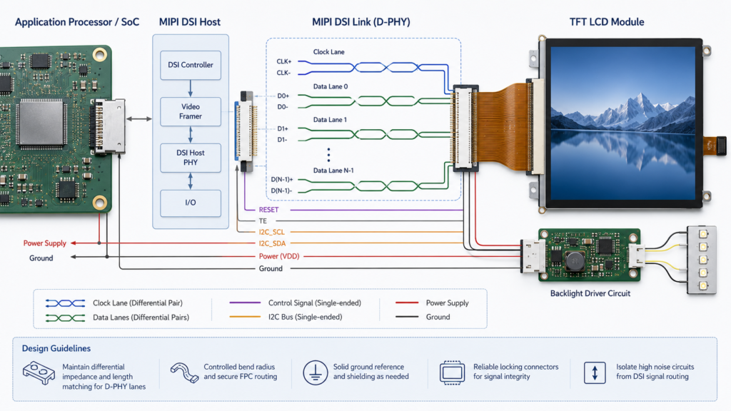
The active resolution is only one input to the required data rate. The engineering calculation must also consider pixel format, refresh rate, blanking timing, packet overhead, selected lane count, and the supported operating range of both host and panel.
As an initial screening relationship:
Active pixel payload ≈ active width × active height × refresh rate × bits per pixel
This is not the final D-PHY configuration because blanking intervals and protocol overhead are not represented in the active-pixel payload. The native pixel clock must be calculated from the complete horizontal and vertical timing.
NXP’s MIPI DSI implementation example calculates the pixel clock from the active dimensions, synchronization widths, porches, and refresh rate. It then requires the high-speed bit clock to be sufficient for the pixel clock, output bits per pixel, and selected number of data lanes.[3]
| Data-Rate Input | Why It Matters |
|---|---|
| Active width and height | Define the visible pixel payload |
| Horizontal and vertical blanking | Increase the complete timing beyond the active image |
| Refresh rate | Changes how often a complete frame must be transmitted |
| Pixel format | Changes the number and packing of transmitted color bits |
| Lane count | Distributes the transmitted data across the implemented lanes |
| Panel and host limits | Define whether the calculated configuration falls within the supported operating range |
Do not approve a panel from a statement such as “the board supports 1080p.” A board may support a standard monitor mode while failing to generate the native timing or lane configuration of a portrait, square, round, or bar-type MIPI panel.
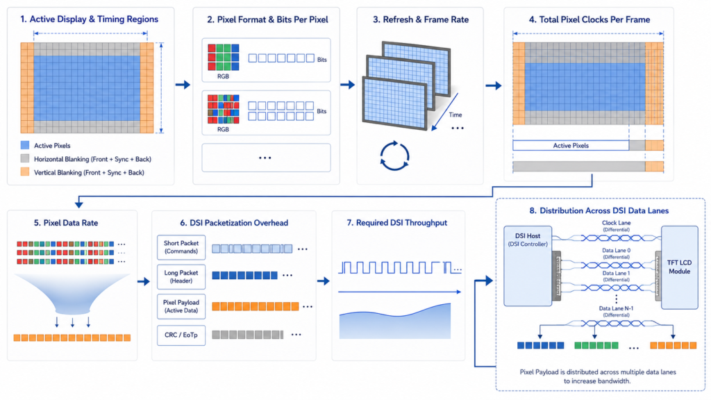
A MIPI panel still has a native display timing. Resolution does not define the pixel clock, synchronization widths, porches, refresh behavior, signal polarity, or complete line and frame structure.
| Timing Item | Required Evidence | Possible Symptom When Incorrect |
|---|---|---|
| Active width and height | Current panel datasheet | Cropped, blank, or unsupported image |
| Pixel clock | Minimum, typical, and maximum values where provided | Unstable image, no synchronization, or artifacts |
| Horizontal porches and sync | Complete line-timing table | Shifted, distorted, or missing image |
| Vertical porches and sync | Complete frame-timing table | Rolling, flicker, or incorrect frame behavior |
| Refresh rate | Supported panel range and target system mode | Unsupported timing or inconsistent visual updates |
| Signal polarity | Panel specification and host configuration | No usable image or unstable output |
NXP’s application note states that timing parameters must be programmed to match the display specification and separately identifies active resolution, pixel clock, synchronization, front porch, back porch, and pulse width.[3]
Request the native timing table before committing the host board or PCB design. A product-page resolution field is not enough for firmware integration.
The host and panel must support the same practical DSI operating configuration. Items to confirm include:
MIPI Display Command Set provides standardized functions for display setup, control, testing, and data delivery.[2] However, a shared command standard does not prove that two panels use an identical initialization sequence or default configuration. The exact driver IC and panel documentation remain controlling.
A host supporting MIPI DSI video mode is not automatically compatible with a panel or module configured for a different mode. This must be checked before firmware work begins.
Many MIPI TFT modules require an ordered initialization sequence before they display an image correctly. The sequence may configure power states, pixel format, orientation, internal timing, gamma-related registers, sleep exit, display enable, or other driver-specific functions.
Request and control:
Do not treat initialization code copied from a visually similar display as evidence for the offered module. Two modules with the same resolution and connector may use different driver ICs or register settings.
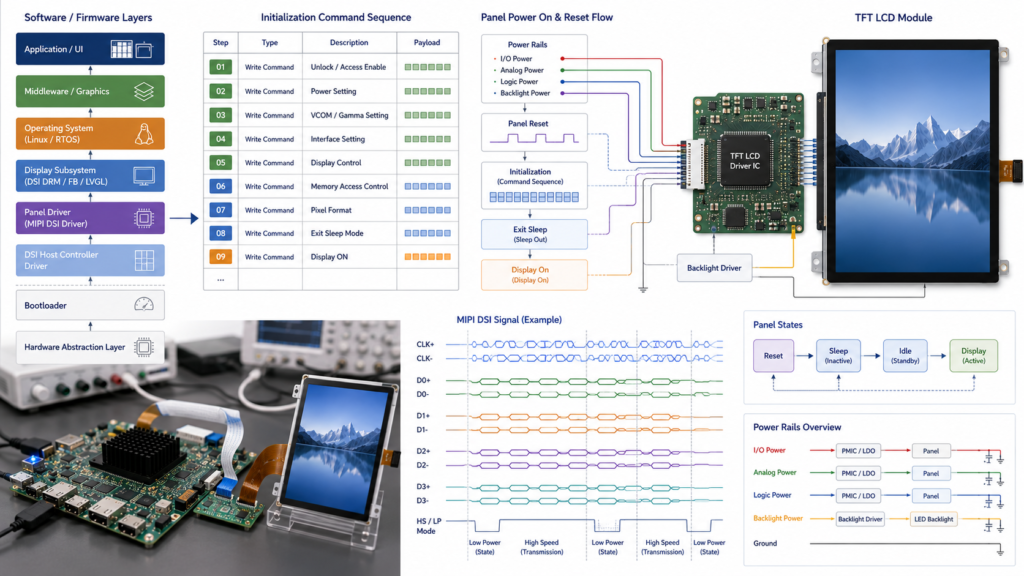
The DSI link carries display data and control traffic, but it does not replace the panel’s power, reset, enable, backlight, and touch requirements.
NXP’s implementation sequence separately configures LCD power, reset, backlight GPIO, native timing, signal polarity, D-PHY clocks, and DSI modules.[3]
| Power or Control Item | Question to Resolve |
|---|---|
| Logic and analog rails | Which voltages, tolerances, currents, and startup order does the module require? |
| Reset | What is the active level, pulse duration, and delay relative to the power rails? |
| Initialization | When may the host begin sending commands after reset and power stabilization? |
| Backlight enable | Should the backlight remain off until the panel is initialized and valid image data is present? |
| Backlight current | Which LED configuration, driver circuit, enable logic, and dimming method are required? |
| Sleep and shutdown | Which command and power-down order prevents unintended states? |
| Interrupted power | Can the panel and controller recover after a brownout or incomplete shutdown? |
A backlight turning on with a black image does not prove that the panel is defective. The failure may be in reset, initialization, timing, D-PHY configuration, data lanes, or the panel driver.
MIPI’s lower pin count does not make PCB and FPC design optional. The high-speed lane path, ground structure, connector, cable, FPC stack, and physical placement must be designed for the implemented D-PHY configuration.
| Hardware Item | Review Question |
|---|---|
| Pin definition | Do all clock, data, power, ground, reset, backlight, and control pins match? |
| Connector | Are pitch, contact side, insertion direction, height, and mating part confirmed? |
| Differential routing | Are the PCB, connector, and FPC designed as one high-speed path? |
| FPC length and exit | Can the tail reach the PCB without an unsupported fold or mechanical interference? |
| Ground and return path | Does the complete connection preserve the intended electrical reference? |
| ESD strategy | Is protection selected and placed without assuming it is electrically transparent? |
| Assembly access | Can the connector be operated and inspected without loading the LCD glass or FPC? |
Matching pin counts do not prove matching pin assignments. Likewise, changing the FPC can require electrical, mechanical, tooling, and validation work even when the LCD glass remains unchanged.
A production MIPI display should be evaluated across every software stage in which an image may be required.
| Software Layer | Required Review |
|---|---|
| Bootloader | Panel power, initialization, startup image, orientation, and handoff to the operating system |
| Kernel or BSP | Panel driver, device description, timing, lanes, mode, reset, regulators, backlight, and touch |
| Graphics framework | Framebuffer size, orientation, density, scaling, compositor, and graphics acceleration |
| Application | Native UI dimensions, rotation, localization, animations, error states, and recovery screens |
| Update and recovery | Whether the display remains usable during firmware update, fallback, and diagnostic modes |
Define which party supplies the panel driver, who can modify it, which source or binary deliverables are included, and how revisions will be controlled. “Custom firmware available” is not a sufficient scope without a named board, OS or SDK version, panel, deliverables, and validation plan.
A MIPI TFT display can be combined with touch when a suitable configuration exists, but the DSI display link does not automatically carry touch input.
NXP notes that display modules may require separate I2C or SPI connections for their touch panels, in addition to backlight-control circuitry and the LCD data path.[3]
Confirm:
Use the TFT LCD module with touch screen guide when touch architecture is a primary project decision.
A panel can be electrically compatible and still be unusable in the product. Review the complete mechanical drawing, not only diagonal size and active area.
| Mechanical Item | What to Confirm |
|---|---|
| Active and viewing area | Alignment with the bezel opening, cover glass, and UI |
| Module outline | Complete width, height, thickness, frame, adhesive, and rear-component envelope |
| FPC envelope | Exit direction, length, stiffener, connector, and safe bend region |
| Cover glass | Outline, printed border, opening, adhesive, edge details, and touch alignment |
| PCB position | Connector access, cable reach, high-speed routing, and serviceability |
| Support structure | Approved mounting and adhesive areas without pressure on active glass |
| Thermal environment | Separation from processors, power supplies, backlight drivers, and local heat sources |
Review the display drawing, host-board layout, and enclosure CAD together before ordering tooling or committing the PCB connector location.
| Architecture | Potential Fit | Main Validation Scope |
|---|---|---|
| Native MIPI DSI Host directly drives the panel | The processor and board expose the correct DSI implementation and the software team controls the panel driver | Lanes, D-PHY, timing, initialization, power, BSP, PCB, touch, and mechanics |
| HDMI-to-MIPI controller board | The source provides HDMI and the selected bridge can generate the panel-specific DSI output | HDMI input mode, bridge capability, output lanes, timing, initialization, firmware, power, backlight, and touch |
| Android or Linux computing board with panel support | The product requires embedded computing, networking, applications, or peripheral control | Board-level DSI implementation, BSP, panel driver, touch, graphics workload, updates, power, and mechanics |
An HDMI-to-MIPI board is an active converter, not a passive connector adapter. Follow the HDMI-to-MIPI controller board compatibility guide when the source does not provide a native DSI Host.
RJY Display’s computing module category provides control-board product paths for initial review. SoC-level specifications should not be substituted for the current board schematic, connector definition, firmware, and hardware revision.
When the core MIPI LCD platform is suitable, a project may evaluate:
| Customization Area | Possible Project Scope | Required Control |
|---|---|---|
| Cover glass | Outline, printing, opening, thickness, and surface requirements | Controlled drawing, tolerance, material, appearance, and touch validation |
| Touchscreen | Sensor, controller, cover stack, bonding, and FPC coordination | Controller, firmware, host interface, coordinates, and environmental testing |
| Backlight | Brightness target, driver coordination, enable, and dimming | Electrical, optical, power, and thermal validation |
| FPC or connector coordination | Tail direction, length, pin routing, connector, and mechanical envelope | High-speed review, drawing, tooling, sample testing, and PCB compatibility |
| Controller board | Native DSI board or bridge-board configuration | Exact board revision, implemented lanes, firmware, power, and peripheral paths |
| Firmware | Panel timing, initialization, orientation, touch, boot, sleep, and wake behavior | Named platform, deliverables, revisions, ownership, and validation |
| Mechanical structure | Cover, supports, bezel, enclosure, PCB position, and cable routing | CAD review, tolerance stack, assembly plan, and sample approval |
See the custom TFT LCD display guide for the broader development and quotation process.
RJY Display’s public product range includes MIPI display paths in different shapes and sizes. Examples include the 8-inch round LCD display and 11.65-inch bar LCD display.
These pages are starting points for product discovery, not compatibility approvals. Before selecting a sample, request the latest datasheet, mechanical drawing, FPC pin definition, native timing, driver IC information, initialization sequence, power requirements, lane configuration, touch specification, and backlight data.
Use the Display Modules category to review additional existing platforms.
| Validation Area | Minimum Review |
|---|---|
| Cold startup | Power sequence, reset, initialization, first valid frame, and backlight enable |
| Image timing | Native resolution, pixel clock, porches, refresh, pixel format, full-screen patterns, and repeated restart |
| DSI link | Lane count, lane rate, selected mode, clock behavior, stable operation, and error recovery |
| UI workload | Representative graphics, animation, video if required, localization, alarms, and error screens |
| Touch | Coordinates, edges, rotation, cover glass, wake, gestures, and electrical-noise exposure |
| Backlight | Enable, dimming, intended operating brightness, power behavior, and enclosure temperature |
| Software lifecycle | Bootloader, kernel or BSP, application, update, recovery, sleep, and wake |
| Mechanical assembly | Alignment, FPC routing, connector access, mounting stress, tolerance stack, and service access |
| Configuration control | LCD, driver IC, board revision, firmware, cable, touch, cover glass, backlight circuit, and enclosure recorded |
Approve the complete configuration rather than only the display model. A later change to the panel driver IC, board revision, FPC, controller firmware, touch controller, backlight, or initialization sequence may require renewed validation.
Prepare the following information:
If replacing another MIPI panel, include the original and proposed datasheets, drawings, pin definitions, timing tables, initialization commands, and current software configuration.
RJY Display can review an existing MIPI TFT LCD platform against your DSI Host, lane configuration, native timing, panel initialization, touch, backlight, FPC, controller-board, firmware, cover-glass, and mechanical requirements.
Browse current display modules, review RJY Display’s custom solution scope, or send your panel, host-board, firmware, and enclosure documents for engineering review.
A custom MIPI TFT LCD display is normally an existing MIPI DSI LCD platform adapted to a project through areas such as touch, cover glass, backlight, FPC, connector coordination, controller board, firmware, or mechanical structure. It does not automatically mean developing a new LCD size or pixel matrix from scratch.
No. The panel and actual host board must match in lane count, lane rate, operating mode, native timing, pixel format, D-PHY configuration, initialization commands, voltage, pin definition, power sequence, firmware, and mechanical connection.
No. Two panels with the same resolution can require different pixel clocks, porches, refresh rates, lane configurations, pixel formats, initialization sequences, power rails, connectors, driver ICs, and firmware.
Usually, the host software must contain configuration for the selected panel, including its timing, lanes, operating mode, reset, power, initialization, and display states. The implementation may be in an MCU project, bootloader, kernel, BSP, or another controlled firmware layer.
No. HDMI and MIPI DSI use different signaling and protocols. A confirmed HDMI-to-MIPI controller or bridge configuration is required, including support for the HDMI input mode, panel output timing, lane configuration, initialization, power, backlight, firmware, and touch path.
Provide the application, display size and resolution, host processor and board revision, DSI lanes and supported modes, operating system or SDK, touch and cover-glass requirements, backlight and power requirements, FPC constraints, mechanical drawing, firmware scope, quantities, and available panel or board documentation.
Share your display size, resolution, interface, brightness, touch requirement, controller board requirement, and application environment.
Continue reading related display technology guides and application references.


Talk to RJY’s engineering team for display matching, controller board review, and customization discussion.









