Incontri un collo di bottiglia nel tuo progetto di display embedded?
Non lasciare che integrazioni complesse o problemi di supply chain rallentino il tuo time-to-market. Prenota una consulenza gratuita con il team di esperti RJY per un supporto su misura in progettazione e produzione.
A display TFT LCD MIPI personalizzato Il progetto non si completa selezionando un pannello con “MIPI” nel campo dell'interfaccia. Il modulo display e l'host devono concordare sull'implementazione DSI, sulla configurazione delle lane, sul timing nativo, sul formato pixel, sui comandi di inizializzazione, sulla sequenza di alimentazione, sul comportamento di reset, sul connettore, sul firmware, sulla retroilluminazione, sul sistema touch e sulla struttura meccanica.
La parola “personalizzato” richiede anche un confine pratico. Per la maggior parte dei progetti OEM, il percorso controllabile inizia con un modulo TFT LCD MIPI. esistente. Il progetto può quindi valutare modifiche attorno a quella piattaforma, come vetro di copertura, touchscreen, retroilluminazione, FPC, coordinamento del connettore, scheda controller, configurazione firmware e integrazione meccanica.
Questa guida spiega come decidere se MIPI DSI è adatto al prodotto, come abbinare un pannello all'host reale e quali informazioni devono essere controllate prima di approvare campioni o attrezzature di produzione.
MIPI DSI è un'interfaccia seriale ad alta velocità tra un processore host e un modulo display. MIPI Alliance la descrive come un'interfaccia progettata per supportare le prestazioni del display riducendo il numero di pin, il consumo energetico e le interferenze elettromagnetiche rispetto alle connessioni parallele più estese.[1]
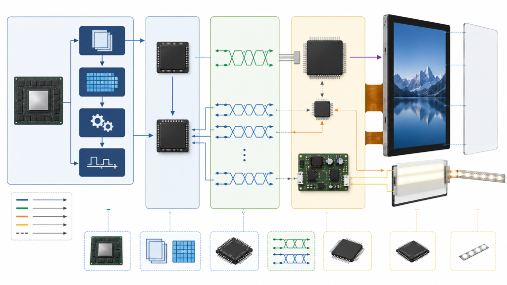
Un tipico sistema display MIPI embedded contiene più del cavo DSI o della FPC:
Elemento del sistema
Funzione
Domanda di progetto
Processore applicativo o MCU
Genera l'interfaccia utente e il framebuffer
Il processore e la scheda reali possono generare la modalità DSI e il timing richiesti dal pannello?
Controller display
Legge i dati dei pixel e genera il flusso video
Supporta la risoluzione, il formato pixel, il requisito di refresh e la larghezza di banda della memoria?
Host MIPI DSI
Confeziona i dati di visualizzazione e il traffico di controllo per il collegamento DSI
Quali conteggi di lane, modalità operative, clock e formati di pacchetto sono implementati?
D-PHY
Fornisce il clock fisico e le lane dati
La scheda può generare la velocità delle lane e la configurazione elettrica richieste?
Modulo TFT LCD
Riceve il flusso e visualizza l'immagine
Quali sono i suoi requisiti di timing nativo, driver IC, inizializzazione, tensione, pinout e retroilluminazione?
Driver del pannello o firmware
Controlla alimentazione, reset, inizializzazione, timing, sleep, wake e stato del display
Il pannello esatto è supportato nel bootloader, nel kernel, nel BSP o nel firmware MCU?
Touch e retroilluminazione
Forniscono input utente e illuminazione
Quali interfacce, driver, circuiti di alimentazione e segnali di controllo separati sono richiesti?
La compatibilità deve essere stabilita lungo l'intero percorso. Una forma del connettore compatibile o una risoluzione corrispondente non è sufficiente.
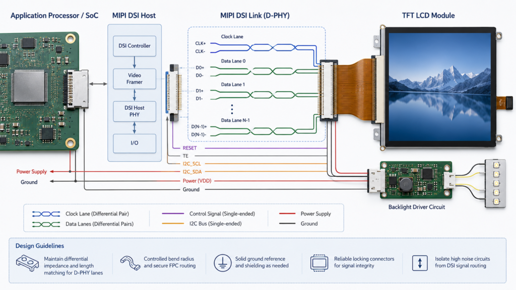
Architettura del display MIPI DSI dal processore applicativo e D-PHY al modulo TFT LCD
Cosa significa “display MIPI personalizzato”?
Il display MIPI personalizzato viene utilizzato per diversi ambiti di progetto. Separarli fin dall'inizio evita che una richiesta di preventivo (RFQ) venga interpretata come una richiesta per una piattaforma LCD completamente nuova.
Tipo di progetto
Ambito pratico
Principale lavoro tecnico
Modulo MIPI standard
Un LCD esistente viene utilizzato senza modifiche fisiche
Compatibilità host, driver del pannello, cavo, alimentazione, retroilluminazione, touch e validazione
Modulo esistente con personalizzazione circostante
L'LCD principale rimane invariato mentre touch, vetro di copertura, retroilluminazione, FPC, coordinamento connettori, firmware o meccanica vengono adattati
Disegni controllati, attrezzature, campioni, firmware, assemblaggio e validazione di sistema
Modulo MIPI con controller o scheda bridge
Una scheda converte o genera l'uscita DSI richiesta dal pannello
Modalità di ingresso, temporizzazione di uscita, inizializzazione del pannello, alimentazione, retroilluminazione, touch, firmware e cablaggio
Richiesta di nuova piattaforma LCD
Le dimensioni richieste, la matrice di pixel o l'architettura principale del pannello non sono disponibili in un modulo esistente
Revisione separata di fattibilità, sviluppo, volume, qualifica e ciclo di vita
Il percorso di personalizzazione pratica di RJY Display inizia con un modulo display esistente. Il lavoro di progetto fattibile può includere vetro di copertura, touchscreen, retroilluminazione, FPC, coordinamento dell'interfaccia, scheda controller, firmware e struttura meccanica. Non deve essere presentato come sviluppo senza restrizioni di qualsiasi nuova dimensione o risoluzione LCD.
Quando MIPI DSI è adatto a un prodotto embedded?
MIPI DSI può essere una scelta appropriata quando il processore effettivo espone un DSI Host supportato, il prodotto ha una connessione display interna breve e il team di ingegneria può controllare il driver del pannello e il firmware di sistema.
Può essere appropriato per:
Prodotti embedded compatti con spazio limitato per connettori e PCB
Piattaforme con processore applicativo o MCU con DSI Host documentato
Display che richiedono una velocità di trasferimento dati pixel superiore a quella che il percorso SPI dell'MCU selezionato può fornire in pratica
Sistemi Android, Linux o RTOS in cui il pannello può essere integrato nella piattaforma software controllata
Display rotondi, quadrati, verticali o a barra la cui temporizzazione nativa è supportata dall'host
Prodotti in cui il processore e il display rimangono all'interno dello stesso assemblaggio controllato
MIPI non è automaticamente la scelta migliore quando:
L'host non espone le corsie DSI richieste o la modalità operativa
Il team software non può implementare o mantenere il driver del pannello
Il display deve comportarsi come un monitor esterno sostituibile
La connessione richiede un'architettura di cavi meglio servita da un'altra interfaccia
Il carico di lavoro dell'interfaccia utente può essere gestito più semplicemente tramite SPI, RGB, LVDS o un altro percorso esistente
Il prodotto esistente ha già un'interfaccia validata e non vi è alcuna ragione tecnica per modificarla
La scelta corretta segue i requisiti di host, display, software, involucro, cavo, prestazioni e ciclo di vita. Non deve basarsi sul presupposto che MIPI sia più moderno e quindi universalmente migliore.
Iniziare dalla scheda host reale, non dal datasheet del SoC
Un datasheet del processore può mostrare che la famiglia SoC contiene un controller MIPI DSI. Ciò non dimostra che una specifica scheda di controllo esponga le corsie, il connettore, le tensioni, i clock, i GPIO, il firmware o il driver del pannello richiesti.
Prima di confrontare i display, raccogliere:
Modello esatto di processore e scheda
Revisione della scheda e informazioni sullo schema elettrico
Numero di porte DSI e corsie dati fisicamente instradate
Connettore della scheda e definizione dei pin
Modalità operative DSI supportate
Velocità massima di corsia supportata per tale implementazione
Linee di alimentazione del pannello disponibili
GPIO per reset, abilitazione, effetto tearing e controllo retroilluminazione
Versione del sistema operativo, kernel, BSP, bootloader o SDK MCU
Driver del pannello esistenti e restrizioni documentate
La revisione dell'host deve essere eseguita a livello di scheda. Una funzionalità elencata per il SoC può non essere disponibile sulla scheda finita perché i pin non sono stati instradati, sono condivisi con un'altra funzione o non sono supportati nel BSP corrente.
Verifica di compatibilità 1: numero di lane e implementazione fisica
Una connessione MIPI DSI normalmente contiene una lane di clock e una o più lane di dati. Il numero esatto supportato dal pannello e il numero esposto dall'host devono essere confermati.
Elemento della linea
Cosa confermare
Capacità delle lane dell'host
Numero di lane di dati implementate sulla scheda effettiva e supportate dal suo software
Requisito delle lane del pannello
Numero di lane supportato o richiesto nel datasheet corrente del pannello
Ordinamento delle lane
Assegnazione tra lane di clock e lane di dati tra il connettore host e il FPC del pannello
Gestione della polarità
Se l'implementazione e il firmware consentono qualsiasi configurazione di polarità delle lane richiesta
Canale virtuale
Configurazione del canale virtuale prevista dall'host e dal dispositivo periferico
Connettore e FPC
Definizione dei pin, orientamento dei contatti, passo, posizionamento della massa e instradamento controllato
La documentazione del device-tree MIPI DSI di Linux rappresenta l'host DSI e i suoi dispositivi periferici collegati come un bus, illustrando che il pannello è un dispositivo periferico configurato piuttosto che un gruppo passivo di cavi differenziali.[4]
Un FPC adattatore può modificare l'instradamento fisico dei pin, ma non può creare lane DSI mancanti né correggere una modalità DSI, una velocità di lane, una temporizzazione o un'implementazione firmware non supportate.
Lane di clock MIPI DSI, lane di dati, connettore, FPC, alimentazione, reset e connessioni per la retroilluminazione
Verifica di compatibilità 2: velocità delle lane e throughput dei pixel
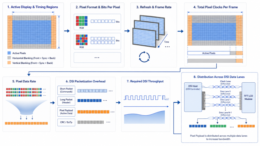
La risoluzione attiva è solo uno degli input per la velocità dati richiesta. Il calcolo ingegneristico deve considerare anche il formato pixel, la frequenza di aggiornamento, la temporizzazione di blanking, l'overhead dei pacchetti, il numero di lane selezionato e l'intervallo operativo supportato sia dall'host che dal pannello.
Come relazione di screening iniziale:
Payload pixel attivo ≈ larghezza attiva × altezza attiva × frequenza di aggiornamento × bit per pixel
Questa non è la configurazione D-PHY finale perché gli intervalli di blanking e l'overhead di protocollo non sono rappresentati nel payload pixel attivo. Il clock pixel nativo deve essere calcolato dalla temporizzazione orizzontale e verticale completa.
L'esempio di implementazione MIPI DSI di NXP calcola il clock pixel dalle dimensioni attive, dalle larghezze di sincronizzazione, dai porche e dalla frequenza di aggiornamento. Richiede quindi che il clock bit ad alta velocità sia sufficiente per il clock pixel, i bit di output per pixel e il numero selezionato di lane di dati.[3]
Input della velocità dati
Perché è importante
Larghezza e altezza attive
Definiscono il payload pixel visibile
Blanking orizzontale e verticale
Aumentano la temporizzazione completa oltre l'immagine attiva
Frequenza di aggiornamento
Modifica la frequenza con cui un fotogramma completo deve essere trasmesso
Formato pixel
Modifica il numero e il confezionamento dei bit di colore trasmessi
Numero di lane
Distribuisce i dati trasmessi attraverso le lane implementate
Limiti del pannello e dell'host
Definiscono se la configurazione calcolata rientra nell'intervallo operativo supportato
Non approvare un pannello sulla base di una dichiarazione come “la scheda supporta 1080p”. Una scheda può supportare una modalità monitor standard senza riuscire a generare la temporizzazione nativa o la configurazione delle lane di un pannello MIPI verticale, quadrato, rotondo o a barra.
Temporizzazione pixel, blanking, formato pixel e fattori delle lane DSI nel throughput dei display MIPI
Verifica di compatibilità 3: timing nativo
Un pannello MIPI ha comunque una temporizzazione di visualizzazione nativa. La risoluzione non definisce il clock pixel, le larghezze di sincronizzazione, i porche, il comportamento di aggiornamento, la polarità del segnale o la struttura completa di linea e fotogramma.
Elemento di temporizzazione
Evidenza Richiesta
Possibile sintomo in caso di errore
Larghezza e altezza attive
Datasheet corrente del pannello
Immagine ritagliata, vuota o non supportata
Clock dei pixel
Valori minimi, tipici e massimi dove forniti
Immagine instabile, assenza di sincronizzazione o artefatti
Porche e sincronizzazione orizzontali
Tabella completa della temporizzazione di linea
Immagine spostata, distorta o mancante
Porche e sincronizzazione verticali
Tabella completa della temporizzazione di fotogramma
Scorrimento, sfarfallio o comportamento di fotogramma errato
Frequenza di aggiornamento
Intervallo supportato del pannello e modalità di sistema target
Temporizzazione non supportata o aggiornamenti visivi incoerenti
Polarità del segnale
Specifiche del pannello e configurazione dell'host
Nessuna immagine utilizzabile o output instabile
La nota applicativa di NXP afferma che i parametri di temporizzazione devono essere programmati per corrispondere alle specifiche del display e identifica separatamente risoluzione attiva, clock dei pixel, sincronizzazione, front porch, back porch e larghezza dell'impulso.[3]
Richiedere la tabella dei tempi nativi prima di impegnare la scheda host o il progetto PCB. Il campo della risoluzione nella pagina del prodotto non è sufficiente per l'integrazione del firmware.
Verifica di compatibilità 4: modalità operativa DSI e formato pixel
L'host e il pannello devono supportare la stessa configurazione operativa DSI pratica. Gli elementi da verificare includono:
Modalità video o modalità comando
Comportamento burst o non-burst applicabile
Formato pixel supportato e impacchettamento dei dati colore
Comportamento del clock continuo o non continuo, ove applicabile
Requisiti di trasmissione comandi a bassa potenza
Requisiti del segnale tearing-effect, ove utilizzato
Sequenza dei dati di visualizzazione e dei comandi di controllo
Il MIPI Display Command Set fornisce funzioni standardizzate per la configurazione del display, il controllo, i test e la consegna dei dati.[2] Tuttavia, uno standard di comando condiviso non dimostra che due pannelli utilizzino una sequenza di inizializzazione o una configurazione predefinita identica. Il driver IC esatto e la documentazione del pannello rimangono determinanti.
Un host che supporta la modalità video MIPI DSI non è automaticamente compatibile con un pannello o modulo configurato per una modalità diversa. Questo deve essere verificato prima di iniziare il lavoro sul firmware.
Verifica di compatibilità 5: driver IC e comandi di inizializzazione
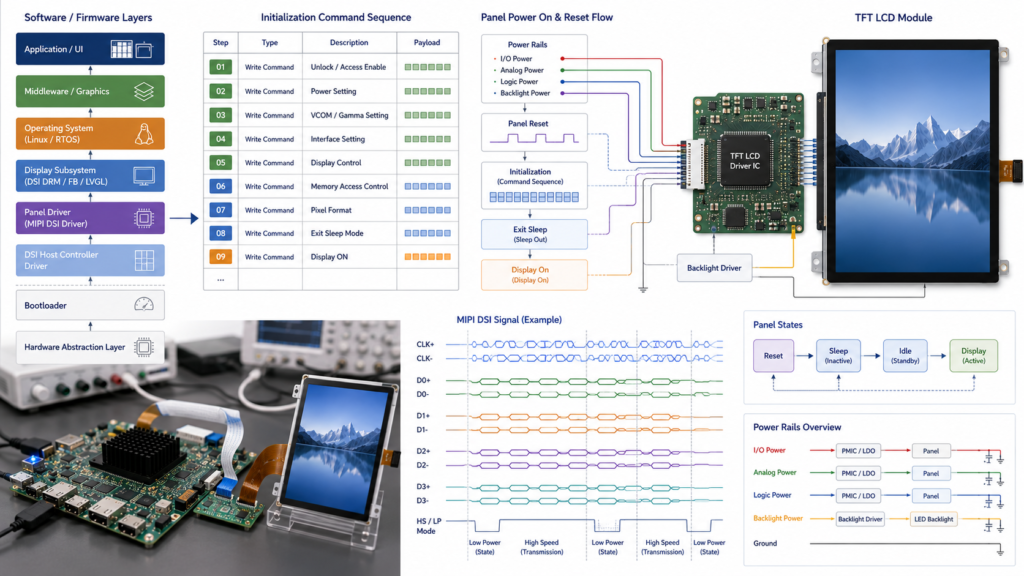
Molti moduli MIPI TFT richiedono una sequenza di inizializzazione ordinata prima di visualizzare correttamente un'immagine. La sequenza può configurare stati di alimentazione, formato pixel, orientamento, temporizzazione interna, registri relativi alla gamma, uscita dalla modalità sleep, abilitazione del display o altre funzioni specifiche del driver.
Richiedere e controllare:
Modello LCD esatto e revisione
Numero del driver IC
Tabella dei comandi di inizializzazione
Tipo di comando, payload, ordine e ritardi richiesti
Stato di reset e temporizzazione
Comportamento sleep-in e sleep-out
Sequenza display-on e display-off
Comandi specifici del produttore richiesti
Differenze tra campioni e revisioni di produzione
Non trattare il codice di inizializzazione copiato da un display visivamente simile come prova per il modulo offerto. Due moduli con la stessa risoluzione e connettore possono utilizzare driver IC o impostazioni di registro diversi.
Driver IC, comandi di inizializzazione, reset, alimentazione e firmware per un LCD MIPI TFT
Verifica di compatibilità 6: sequenza di alimentazione, reset e retroilluminazione
Il collegamento DSI trasporta dati di visualizzazione e traffico di controllo, ma non sostituisce i requisiti di alimentazione, reset, abilitazione, retroilluminazione e touch del pannello.
La sequenza di implementazione di NXP configura separatamente alimentazione LCD, reset, GPIO retroilluminazione, temporizzazione nativa, polarità del segnale, clock D-PHY e moduli DSI.[3]
Elemento di alimentazione o controllo
Domanda da Risolvere
Linee di alimentazione logica e analogica
Quali tensioni, tolleranze, correnti e ordine di avvio richiede il modulo?
Reset
Qual è il livello attivo, la durata dell'impulso e il ritardo rispetto alle linee di alimentazione?
Inizializzazione
Quando può l'host iniziare a inviare comandi dopo il reset e la stabilizzazione dell'alimentazione?
Abilitazione retroilluminazione
La retroilluminazione deve rimanere spenta fino a quando il pannello non è inizializzato e sono presenti dati immagine validi?
Corrente della retroilluminazione
Quale configurazione LED, circuito driver, logica di abilitazione e metodo di dimming sono richiesti?
Sleep e spegnimento
Quale ordine di comandi e di spegnimento previene stati indesiderati?
Alimentazione interrotta
Il pannello e il controller possono recuperare dopo un brownout o uno spegnimento incompleto?
Una retroilluminazione che si accende con un'immagine nera non dimostra che il pannello sia difettoso. Il guasto potrebbe essere nel reset, nell'inizializzazione, nella temporizzazione, nella configurazione D-PHY, nelle linee dati o nel driver del pannello.
Verifica di compatibilità 7: FPC, connettore e layout PCB
Il minor numero di pin di MIPI non rende opzionale la progettazione di PCB e FPC. Il percorso delle linee ad alta velocità, la struttura di massa, il connettore, il cavo, lo stack FPC e il posizionamento fisico devono essere progettati per la configurazione D-PHY implementata.
Elemento hardware
Domanda di Revisione
Definizione dei pin
Tutti i pin di clock, dati, alimentazione, massa, reset, retroilluminazione e controllo corrispondono?
Connettore
Sono confermati passo, lato di contatto, direzione di inserimento, altezza e parte di accoppiamento?
Host MIPI diretto o scheda controller HDMI-to-MIPI?
Architettura
潜在适配性
Ambito principale di validazione
原生MIPI DSI主机直接驱动面板
Il processore e la scheda espongono la corretta implementazione DSI e il team software controlla il driver del pannello
Lanes, D-PHY, temporizzazione, inizializzazione, alimentazione, BSP, PCB, touch e meccanica
Scheda controller HDMI-to-MIPI
La sorgente fornisce HDMI e il bridge selezionato può generare l'uscita DSI specifica del pannello
Modalità ingresso HDMI, capacità del bridge, lanes di uscita, temporizzazione, inizializzazione, firmware, alimentazione, retroilluminazione e touch
Scheda di calcolo Android o Linux con supporto pannello
Il prodotto richiede calcolo embedded, networking, applicazioni o controllo periferiche
Implementazione DSI a livello di scheda, BSP, driver del pannello, touch, carico grafico, aggiornamenti, alimentazione e meccanica
Una scheda HDMI-to-MIPI è un convertitore attivo, non un adattatore passivo di connettori. Seguire le fornisce la sequenza di revisione dettagliata. quando la sorgente non fornisce un host DSI nativo.
RJY Display's categoria del modulo di calcolo fornisce percorsi di prodotto a livello di scheda di controllo per la revisione iniziale. Le specifiche a livello di SoC non devono essere sostituite allo schema elettrico corrente della scheda, alla definizione dei connettori, al firmware e alla revisione hardware.
Cosa può essere personalizzato attorno a un modulo MIPI esistente?
Quando la piattaforma LCD MIPI core è adatta, un progetto può valutare:
Area di Personalizzazione
Possibile ambito del progetto
Controllo richiesto
Vetro di copertura
Profilo, stampa, apertura, spessore e requisiti di superficie
Disegno controllato, tolleranza, materiale, aspetto e validazione touch
Touchscreen
Sensore, controller, stack del coperchio, bonding e coordinamento FPC
Controller, firmware, interfaccia host, coordinate e test ambientali
Retroilluminazione
Obiettivo di luminosità, coordinamento driver, abilitazione e dimming
Validazione elettrica, ottica, di alimentazione e termica
Coordinamento FPC o connettore
Direzione della coda, lunghezza, instradamento pin, connettore e ingombro meccanico
Revisione ad alta velocità, disegno, attrezzature, test campioni e compatibilità PCB
Scheda di controllo
Configurazione con scheda DSI nativa o scheda bridge
Revisione esatta della scheda, lanes implementate, firmware, alimentazione e percorsi periferici
Firmware
Temporizzazione del pannello, inizializzazione, orientamento, touch, avvio, sospensione e comportamento di wake
Piattaforma nominata, deliverable, revisioni, responsabilità e validazione
Struttura meccanica
Coperchio, supporti, cornice, involucro, posizione PCB e instradamento cavi
Revisione CAD, catena di tolleranze, piano di assemblaggio e approvazione campioni
Queste pagine sono punti di partenza per la scoperta del prodotto, non approvazioni di compatibilità. Prima di selezionare un campione, richiedere l'ultima scheda tecnica, il disegno meccanico, la definizione dei pin FPC, la temporizzazione nativa, le informazioni sul driver IC, la sequenza di inizializzazione, i requisiti di alimentazione, la configurazione delle lanes, le specifiche touch e i dati di retroilluminazione.
Sequenza di alimentazione, reset, inizializzazione, primo frame valido e abilitazione retroilluminazione
Temporizzazione immagine
Risoluzione nativa, clock pixel, porches, refresh, formato pixel, pattern a schermo intero e riavvio ripetuto
Collegamento DSI
Numero di lanes, velocità delle lanes, modalità selezionata, comportamento del clock, funzionamento stabile e recupero errori
Carico UI
Grafica rappresentativa, animazione, video se richiesto, localizzazione, allarmi e schermate di errore
Toccare
Coordinate, bordi, rotazione, vetro di copertura, wake, gesti ed esposizione a rumore elettrico
Retroilluminazione
Abilitazione, dimming, luminosità operativa prevista, comportamento di alimentazione e temperatura dell'involucro
Ciclo di vita del software
Bootloader, kernel o BSP, applicazione, aggiornamento, ripristino, sospensione e wake
Assemblaggio meccanico
Allineamento, instradamento FPC, accesso al connettore, stress di montaggio, catena di tolleranze e accesso per assistenza
Controllo della configurazione
LCD, driver IC, revisione scheda, firmware, cavo, touch, vetro di copertura, circuito di retroilluminazione e involucro registrati
Approvare la configurazione completa piuttosto che solo il modello di display. Una modifica successiva al driver IC del pannello, alla revisione della scheda, al FPC, al firmware del controller, al controller touch, alla retroilluminazione o alla sequenza di inizializzazione può richiedere una nuova validazione.
Cosa inviare per una revisione di un display MIPI personalizzato
Preparare le seguenti informazioni:
Prodotto target e ambiente applicativo
Area attiva richiesta, risoluzione, orientamento e ingombro meccanico
Carico di lavoro rappresentativo per grafica e artwork UI
Modello e revisione esatti di processore, scheda di controllo o MCU
Documentazione disponibile per host MIPI DSI
Numero di linee dati instradate e definizione del connettore di scheda
Modalità DSI supportata, intervallo di lane-rate e formato pixel
Versione del sistema operativo, kernel, BSP, bootloader o SDK MCU
Informazioni su driver pannello esistente o display di riferimento
Requisiti per touch-controller e input host
Requisiti per cover-glass e bonding
Luminosità, retroilluminazione, dimming, alimentazione e condizioni di visualizzazione
Direzione FPC, posizione del connettore e vincoli PCB
Disegno meccanico o CAD dell'alloggiamento
Prototipo, pilotaggio, produzione e quantità annuali previste
Condizioni di validazione richieste e aspettative di ciclo di vita
Se si sostituisce un altro pannello MIPI, includere i datasheet originali e proposti, disegni, definizioni pin, tabelle di temporizzazione, comandi di inizializzazione e configurazione software corrente.
Richiedere una revisione di compatibilità TFT LCD MIPI
RJY Display può valutare una piattaforma MIPI TFT LCD esistente rispetto al proprio host DSI, configurazione delle lane, temporizzazione nativa, inizializzazione del pannello, touch, retroilluminazione, FPC, scheda di controllo, firmware, cover-glass e requisiti meccanici.
Un display MIPI TFT LCD personalizzato è normalmente una piattaforma MIPI DSI LCD esistente adattata a un progetto tramite aree quali touch, cover glass, retroilluminazione, FPC, coordinamento connettori, scheda di controllo, firmware o struttura meccanica. Non implica automaticamente lo sviluppo di una nuova dimensione LCD o matrice di pixel da zero.
Qualsiasi display MIPI DSI può connettersi a un processore abilitato MIPI?
No. Il pannello e la scheda host effettiva devono corrispondere in numero di lane, lane rate, modalità operativa, temporizzazione nativa, formato pixel, configurazione D-PHY, comandi di inizializzazione, tensione, definizione pin, sequenza di alimentazione, firmware e connessione meccanica.
È sufficiente corrispondere la risoluzione per confermare la compatibilità del display MIPI?
No. Due pannelli con la stessa risoluzione possono richiedere clock pixel, porche, frequenze di refresh, configurazioni delle lane, formati pixel, sequenze di inizializzazione, alimentazioni, connettori, driver IC e firmware diversi.
Un MIPI TFT LCD richiede un driver di pannello?
Di solito, il software host deve contenere la configurazione per il pannello selezionato, inclusi temporizzazione, lane, modalità operativa, reset, alimentazione, inizializzazione e stati di visualizzazione. L'implementazione può trovarsi in un progetto MCU, bootloader, kernel, BSP o altro livello firmware controllato.
HDMI può connettersi direttamente a un pannello MIPI DSI?
No. HDMI e MIPI DSI utilizzano segnali e protocolli diversi. È richiesta una configurazione confermata di controller o bridge HDMI-to-MIPI, incluso il supporto per la modalità di ingresso HDMI, temporizzazione di uscita del pannello, configurazione delle lane, inizializzazione, alimentazione, retroilluminazione, firmware e percorso touch.
Quali informazioni sono necessarie per un preventivo di display MIPI personalizzato?
Fornire applicazione, dimensione e risoluzione del display, processore host e revisione della scheda, lane DSI e modalità supportate, sistema operativo o SDK, requisiti touch e cover-glass, requisiti di retroilluminazione e alimentazione, vincoli FPC, disegno meccanico, ambito firmware, quantità e documentazione disponibile di pannello o scheda.
Condividi le dimensioni del display, la risoluzione, l'interfaccia, la luminosità, i requisiti tattili, i requisiti della scheda controller e l'ambiente applicativo.