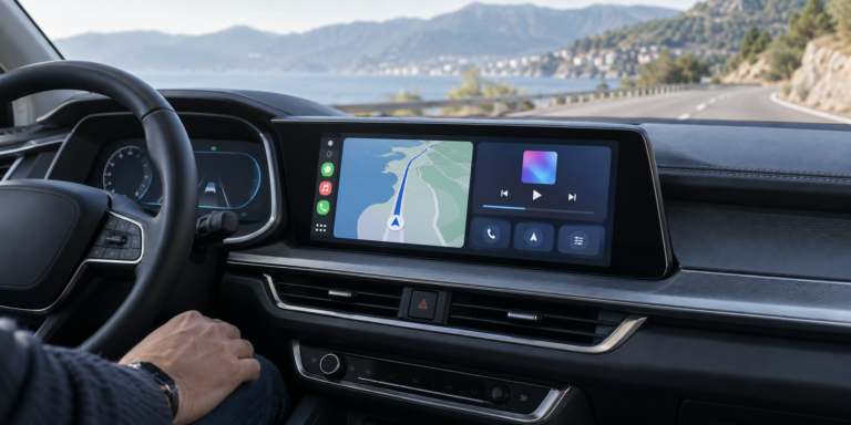
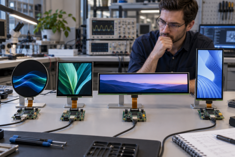
Facing a bottleneck in your Embedded Display Project?
Don’t let complex integration or supply chain issues slow your time-to-market. Book a free consultation with the RJY expert team for tailored design and manufacturing support.

An industrial generator set can combine an engine, alternator, engine-control electronics, voltage regulation, a genset controller, protection functions, breakers, an automatic transfer switch, remote communications, and a local operator interface. The TFT LCD is important to that interface, but it is not the engine controller, automatic voltage regulator, generator protection relay, breaker controller, transfer switch, or remote monitoring platform.
Display selection should begin with the work performed at the generator. Operators and service personnel may need to identify the equipment state, confirm the selected operating context, review events, observe communication availability, and navigate approved maintenance functions. These workflows determine the useful display area, resolution, touch behavior, host architecture, optical stack, mounting, and validation plan.
This guide explains how to select and integrate a TFT LCD for an industrial generator set HMI while keeping the display, touch input, HMI host, genset controller, engine and alternator functions, ATS, physical controls, and remote monitoring clearly separated.
A generator-set architecture should identify every control and display domain before samples are selected. The genset controller receives the appropriate engine, generator, breaker, and system information and executes the functions defined by the equipment manufacturer. Engine-control electronics may manage engine-specific operation. An automatic voltage regulator controls the alternator excitation path. Protection and breaker functions belong to their respective system layers.
The embedded HMI host renders selected information and drives the TFT LCD. The panel itself only presents pixel data through a compatible native display interface. It does not measure voltage or frequency, regulate excitation, control engine speed, synchronize sources, operate a breaker, determine a protection trip, or prove that the generator is ready to accept load.
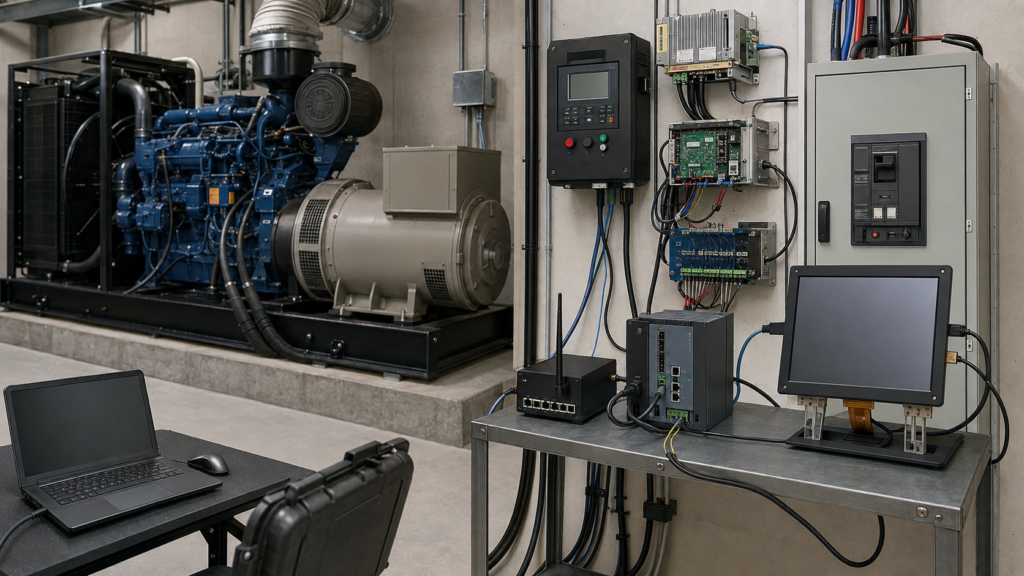
Current controller documentation demonstrates why these functions must remain separate. DEIF describes generator-controller variants, remote display units, and remote monitoring as distinct elements in a power-generation architecture.1 A raw TFT LCD should not be presented as providing the complete functions of any of those products.
Create an architecture diagram that identifies the genset controller, HMI host, native display output, touch controller, AVR, engine-control electronics, protection devices, breakers, ATS, remote gateway, physical controls, power rails, and startup dependencies. This prevents the display supplier from being assigned control or safety responsibilities that belong elsewhere.
The local HMI should support defined decisions beside the generator rather than reproduce every view available on a remote fleet-management system. Start by identifying the user roles, information required locally, permitted commands, access levels, and expected behavior when communications are unavailable.
A routine overview may prioritize equipment identity, availability, operating mode, communication state, active events, and maintenance context. Authorized service screens may expose deeper controller, input/output, configuration, and event-history information. The exact content must follow the equipment architecture and should not be inferred from the display hardware.
Build representative GUI screens before choosing the panel size. Include realistic equipment names, long event messages, permissions, confirmation dialogs, unavailable values, timestamps, translations, maintenance navigation, and any virtual keyboard. Placeholder screens can make a small display appear more suitable than it will be with production content.
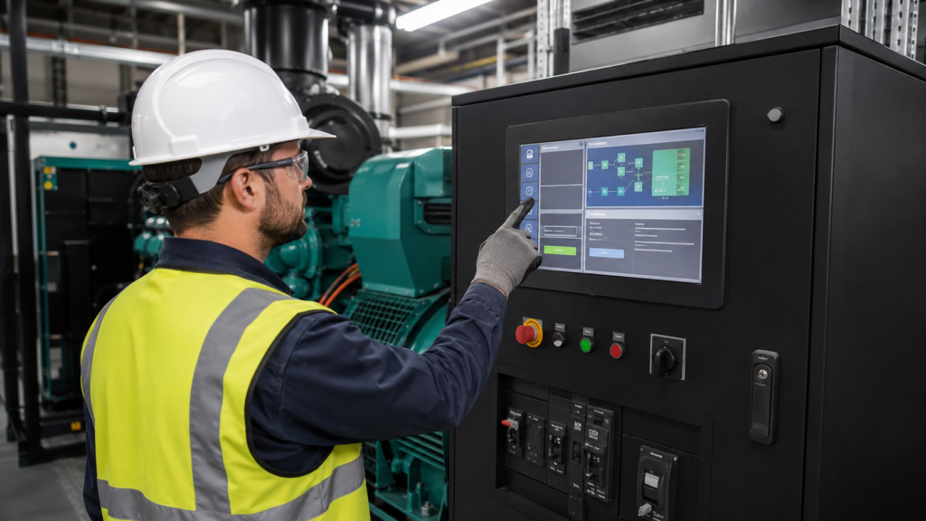
The interface must distinguish displayed information from control authority. A value shown on the screen does not validate its measurement source. A graphical start request does not prove that the generator can start or connect. The controller must evaluate permissions, operating state, protection conditions, breaker state, and the completed system logic.
A standby or distributed-power installation may contain a generator-set controller, automatic transfer switch, switchgear, mains controller, synchronizing equipment, or plant power-management system. These components can exchange data but do not necessarily use the same controller, user interface, authority, or startup sequence.
An ATS interface may display the condition of available sources, transfer equipment, and related events. A genset HMI may focus on the engine-generator package and its controller. A switchgear HMI can aggregate multiple breakers or generator controllers. The project specification should state which equipment owns each command and which interface presents it.
Eaton’s current remote-annunciator information illustrates that an ATS-oriented touchscreen can monitor and interact with transfer-switch controllers as a distinct system.2 This is different from a raw LCD module and different from assuming that the local generator screen itself performs the transfer function.
Do not duplicate critical controls casually across screens. If a function is available from more than one interface, the completed system must define permissions, state reconciliation, event recording, communication-loss behavior, and which controller has authority.
The correct panel size depends on mounting position, viewing distance, standing or service posture, information density, touch-target requirements, enclosure space, and whether the user wears gloves. An indoor generator-room panel and an outdoor enclosure can create different optical and mechanical requirements.
Review the representative GUI at the proposed physical size. Confirm that users can identify the selected generator, current context, event priority, communication state, and age of displayed information without excessive navigation. Status regions, navigation, confirmation dialogs, and long translated messages must remain readable.
Resolution should support the necessary typography and graphics without imposing an unnecessary load on the HMI host. Higher resolution can increase framebuffer size, memory bandwidth, graphics rendering, boot time, and thermal demand. Evaluate the panel, processor, operating system, graphics framework, and application together.
A local embedded panel does not need to reproduce every multi-site trend or fleet-management dashboard available remotely. Select the display for its local operating and maintenance role.
Raw TFT LCD modules may use RGB, LVDS, MIPI DSI, eDP, or another defined native interface. Compatibility requires more than a shared interface name. The host and panel must agree on electrical levels, lane or bus configuration, pixel format, resolution, display timing, connector pinout, initialization, orientation, backlight control, and power sequence.
NXP’s LCDIF driver documentation illustrates why configuration must be verified for the exact platform. It defines interface and timing parameters rather than promising that any processor, cable, software stack, and TFT panel will operate together automatically.3
If the selected HMI computer provides HDMI while the raw panel requires MIPI DSI, RGB, LVDS, or eDP, a passive cable cannot perform the conversion. The design requires a compatible active controller or bridge. That component becomes part of the firmware, startup, power, backlight, thermal, EMC, cable, and lifecycle plan.
A completed external HDMI monitor and a raw embedded TFT are different deliverables. The external monitor contains receiving and display-control electronics. The raw panel requires a compatible native output or an intentionally selected active conversion path.
The LCD interface carries pixel data. A projected-capacitive or resistive touch system uses its own sensor, controller, electrical connection, firmware configuration, grounding arrangement, and software input path. Combining the LCD and touch sensor mechanically does not combine these functions electrically.
Touch requirements should reflect the intended operating condition. Review glove material, moisture, dust, oil residue, cleaning procedures, cover-lens thickness, target dimensions, grounding, enclosure construction, and nearby electrical noise. A generic capacitive-touch description does not establish reliable operation in every generator enclosure.
Test deliberate taps, edge targets, drag actions where used, rejected contacts, virtual-keyboard use, startup behavior, and recovery after a touch-controller or application restart. Evaluate the intended cover stack, host, enclosure, cable routing, and grounding together.
Emergency stop, breaker control, mode selection, isolation, and other functions identified by the equipment design or risk assessment may require independent physical controls. A graphical control can be affected by a display, touch, software, power, or communication failure and should not be presented as an inherently independent safety function.
A local TFT HMI, a controller-specific remote display, and a remote monitoring workstation can all present generator information, but they normally serve different locations, users, and system boundaries. The local HMI is integrated into or near the generator. A remote display may provide access to a defined master controller over a local network. A fleet platform may aggregate many sites and controllers.
DEIF’s current generator-controller information identifies a remote display as a separate unit providing access to a master controller, while its remote-monitoring service is a separate platform for broader equipment access.1 These examples reinforce that “remote display” is not a property of a bare TFT LCD.
The project specification should define what remains available locally when the remote network is unavailable, which actions may be requested remotely, how users recognize the source and age of data, and how conflicting or delayed commands are handled by the controller architecture.
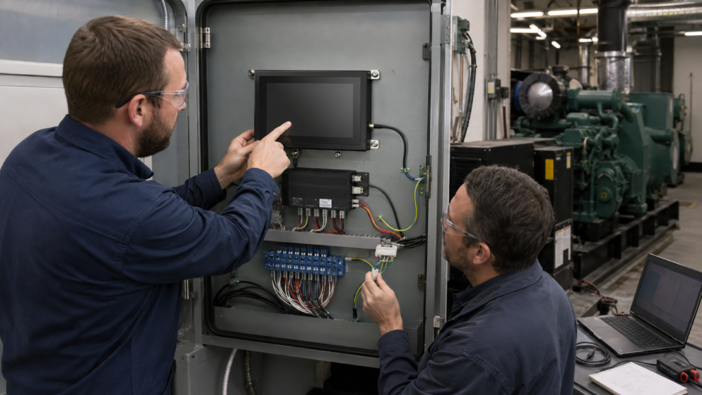
A larger external monitor is also electrically different from a raw embedded panel. The finished monitor includes its own input electronics, whereas the native TFT depends on the compatible HMI host, panel power, backlight control, touch connection, and mechanical integration.
A display that works on an open bench is not yet a production-ready genset HMI. Review the enclosure opening, active-area visibility, cover lens, mounting, connector access, FPC bend radius, cable retention, strain relief, service clearance, grounding, shielding, and heat around the display and HMI electronics.
Generator installations may combine vibration, engine heat, airflow, dust, oil residue, changing lighting, service activity, and electrically noisy equipment. Outdoor packages can add sunlight, low-temperature startup, condensation, rain exposure, and enclosure heating. The actual conditions at the display location must be defined by the equipment OEM.
Evaluate readability using the intended GUI, viewing direction, mounting angle, cover stack, and representative lighting. Brightness alone does not prove sunlight readability because reflections, contrast, surface treatment, cover materials, and screen content also affect the completed result.
A display module or cover lens does not establish an ingress-protection, vibration, EMC, temperature, or chemical-resistance rating for the complete generator cabinet. Any such claim requires a defined production assembly and applicable verification.
The HMI power path may behave differently from the engine-control, starter-battery, auxiliary-power, breaker, ATS, or remote-network paths. Define the sequence for panel power, display-interface initialization, backlight enable, HMI-host boot, touch availability, application launch, controller communication, and receipt of valid generator data.
The display should not present retained values as if they were current. Specify how the application represents unavailable, delayed, invalid, or partially updated information when communication with the genset controller, ATS, switchgear, or remote platform is interrupted.
Review behavior during auxiliary-power loss, controller restart, HMI restart, incomplete startup, network interruption, and reconnection. The controller and protection architecture determine equipment behavior; the display communicates the resulting state without replacing those functions.
Repeated power cycling, touch recovery, restoration of user permissions, correct equipment identity, event-state restoration, and the distinction between local and remote availability should be included in system testing.
Validation should progress from electrical bring-up to the selected TFT, touch stack, HMI host, active bridge where used, cables, power supply, enclosure, application, genset controller, ATS or switchgear connection, and intended installation environment.
Use representative operator and service workflows. Test equipment identity, operating states, permissions, long event messages, unavailable information, startup, restart, communication loss, power interruption, and recovery. Assess readability from the intended user positions and touch behavior with the expected gloves and cover construction.
Mechanical review should include assembly tolerance, active-area alignment, FPC routing, connector retention, strain relief, cabinet access, service replacement, vibration exposure, and thermal conditions. Include any active video controller in the firmware, startup, EMC, thermal, and lifecycle plan.
Write measurable acceptance criteria before design freeze. Terms such as “sunlight readable,” “outdoor,” “glove touch,” “real time,” “industrial grade,” or “vibration resistant” are incomplete without a defined condition, system boundary, test method, and required result.
Provide the target active area, enclosure drawing, mounting position, orientation, representative GUI, viewing conditions, host processor or board, native display outputs, operating system, touch and cover requirements, glove and cleaning conditions, power sequence, cable constraints, installation environment, project stage, and expected demand range.
Identify the requested delivery boundary: a raw TFT LCD, LCD-and-touch assembly, covered display assembly, LCD with an active video controller, embedded computing platform, remote display unit, or a more complete HMI subsystem. These are different products and require different compatibility evidence.
RJY Display can review applicable existing display platforms and project-specific customization involving touch, cover construction, backlight, FPC, interface, controller board, and mechanical coordination. Feasibility depends on the selected platform and confirmed requirements. This does not imply that any arbitrary LCD cell size can be developed from zero or that RJY qualifies the generator, ATS, switchgear, protection, synchronization, or safety system.
Contact RJY Display for an industrial generator set HMI display review and provide the GUI, host, interface, touch, optical, mechanical, environmental, and workflow information required to evaluate the display layer.
No. The TFT LCD presents pixels. A complete HMI also requires a host, software, input devices, power, communications, mechanical integration, and defined interaction with the genset controller.
No. The HMI can present selected ATS information when the system supports it, but source sensing, transfer logic, switching, interlocks, and related protection belong to the completed ATS and power-system architecture.
Not automatically. Local and remote interfaces can have different availability, permissions, data paths, electrical architectures, and service roles. The equipment designer must define which functions remain available locally.
No. A passive cable cannot convert HDMI into a raw MIPI, RGB, LVDS, or eDP panel interface. A compatible active controller or bridge is required and must support the source and exact panel requirements.
Provide the enclosure and active-area target, representative GUI, host platform, native display outputs, operating system, touch and cover requirements, viewing and environmental conditions, cable and power constraints, project stage, and expected demand range.
Share your display size, resolution, interface, brightness, touch requirement, controller board requirement, and application environment.
Continue reading related display technology guides and application references.
Talk to RJY’s engineering team for display matching, controller board review, and customization discussion.