Facing a bottleneck in your Embedded Display Project?
Don’t let complex integration or supply chain issues slow your time-to-market. Book a free consultation with the RJY expert team for tailored design and manufacturing support.

A bar LCD display can place status information, controls, navigation, or equipment data inside a space that cannot accommodate a conventional rectangular screen. Its unusual shape, however, changes how the display must be selected and integrated.
Diagonal size alone is not enough. An engineering team also needs the active-area dimensions, pixel matrix, native timing, module outline, interface, touch structure, backlight requirements, FPC direction, and a host platform capable of rendering the intended user interface.
The correct selection process therefore begins with the product’s physical window and UI workload. It does not begin by choosing the longest or highest-resolution panel in a catalog.
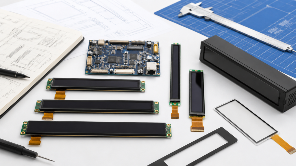
A bar LCD is a TFT LCD module with a substantially elongated display area. It may also be described as a bar-type, strip, stretched, or ultra-wide LCD. These names describe the general shape, but they do not define an interchangeable electrical or mechanical standard.
A bar display can be mounted horizontally or vertically. The product orientation does not necessarily match the panel’s native pixel orientation, FPC exit direction, or initialization configuration. Those details must be checked from the current panel datasheet and mechanical drawing.
RJY Display’s current bar display category shows six public product paths spanning different physical sizes and interface configurations.[1] Each model should be evaluated as an individual module rather than as a scaled version of another bar display.
Two displays with similar diagonal measurements can have very different widths and heights when their aspect ratios differ. The diagonal also says nothing about the position of the active area, the frame around it, the FPC exit, or the components on the rear of the module.
Define the following dimensions before comparing products:
| Dimension | What It Describes | Why It Matters |
|---|---|---|
| Active area | The physical area in which pixels produce an image | Determines the actual visual canvas and pixel density |
| Viewing area | The opening through which the image is intended to be viewed | Must align with the bezel, cover glass, and enclosure |
| Module outline | The complete width, height, and thickness of the display assembly | Controls fit, mounting clearance, and assembly access |
| Cover-glass outline | The external lens dimensions when cover glass is included | Affects the front enclosure, adhesive area, and cosmetic border |
| FPC envelope | The cable location, length, direction, and bend area | Controls PCB placement and prevents cable stress |
| Component keep-out area | Space needed around driver, connector, frame, or rear components | Prevents interference with supports, fasteners, and the main PCB |
Request the dimensioned drawing rather than estimating these values from a product photograph. The drawing should be reviewed together with the enclosure model before either component is released for tooling.
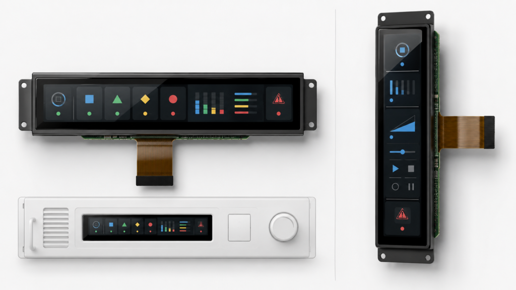
Bar displays often use pixel matrices that are much longer in one direction than the other. This is useful for timelines, equipment status, navigation, grouped controls, media information, appliance interfaces, or secondary dashboards, but the application must be designed for the actual canvas.
Rotating a conventional UI does not automatically make it suitable for a narrow screen. A design created for a standard desktop or tablet aspect ratio may produce clipped dialogs, unreadable text, oversized margins, or controls that cannot be reached without excessive scrolling.
| UI Requirement | Display Implication | Question to Resolve |
|---|---|---|
| One-line equipment status | Benefits from a long horizontal canvas | Can the required text remain legible at the intended viewing distance? |
| Vertical control strip | Requires a narrow portrait layout | Will controls, warnings, and touch targets fit across the short dimension? |
| Several live data fields | Requires sufficient resolution and rendering performance | Which values must remain visible simultaneously? |
| Animation or video | Increases graphics, memory, bandwidth, and software requirements | Can the host sustain the required update rate at the native resolution? |
| Multiple languages | May require flexible text areas and larger fonts | Has the longest translated text been tested on the real canvas? |
Create representative UI screens at the panel’s native pixel dimensions before approving the display. Include alarms, long translated strings, maintenance dialogs, startup screens, error states, and any on-screen keyboard required by the product.
Aspect ratio describes the relationship between the long and short dimensions of the image. It should be calculated from the active pixel matrix and considered together with the physical active area.
Pixel density can help compare text and graphic size between candidate displays, but a higher PPI value is not automatically better. The appropriate density depends on viewing distance, font rendering, UI scale, processor capability, and the amount of information that must be shown.
RJY Display’s TFT LCD parameter calculator can provide an initial estimate of aspect ratio, pixel pitch, and PPI. The result should then be checked with full-scale UI artwork and, when possible, a physical sample.
Do not compare panels solely by total pixel count. A long, narrow matrix and a conventional rectangular matrix may contain a similar number of pixels while creating entirely different layouts.
Resolution identifies only the active pixels. A display controller also needs the complete native timing, including pixel clock, horizontal and vertical synchronization, front porch, back porch, refresh rate, signal polarity, and pixel format where applicable.
NXP’s MIPI DSI display application note shows that panel integration includes power, reset, backlight GPIO, timing parameters, signal polarity, pixel clock, D-PHY configuration, and the panel driver—not only the active resolution.[2]
| Timing Item | Why It Must Be Confirmed | Possible Symptom When Incorrect |
|---|---|---|
| Active width and height | Defines the native image matrix | Cropped, blank, or unsupported image |
| Pixel clock | Controls the rate at which pixel data is transmitted | Unstable image or failure to synchronize |
| Horizontal and vertical porches | Define the blanking intervals around the active image | Shifted, rolling, or distorted image |
| Refresh rate | Affects bandwidth and visual update behavior | Flicker, artifacts, or unsupported timing |
| Pixel format | Defines color-data packing | Wrong colors or no usable image |
| Initialization sequence | Configures the panel driver before normal operation | Backlight on with no image |
A host that supports a larger maximum resolution is not automatically compatible with every smaller bar-panel timing. The exact mode must be available from the host, implemented in the BSP, or generated by a suitable controller-board configuration.
The interface printed on a product page is an initial screening item. Compatibility still depends on the electrical configuration, timing, pin definition, firmware, and connector implementation.
| Interface Route | Potential Project Fit | Items to Confirm |
|---|---|---|
| SPI | Compact MCU-based interfaces with a suitable update workload | Bus mode, pixel format, initialization, practical update rate, and driver support |
| RGB | Direct parallel connection to a compatible display controller | Data width, voltage, timing, synchronization, PCB routing, and FPC pinout |
| MIPI DSI | Compact embedded systems using a supported application processor or bridge | Lane count, lane rate, operating mode, timing, initialization, power sequence, and firmware |
| LVDS | Supported embedded systems and larger display configurations | Channel configuration, mapping, voltage, timing, cable, connector, and backlight |
| HDMI or other external video source | PC, single-board computer, or separated display-controller architecture | Native output mode, scaling, rotation, bridge compatibility, EDID behavior, and separate touch path |
MIPI DSI is a host-to-display interface that supports high-speed communication between a processor and display module.[3] That definition does not make every MIPI panel compatible with every MIPI host. Lane configuration, timing, operating mode, initialization, pinout, power, and firmware remain panel-specific.
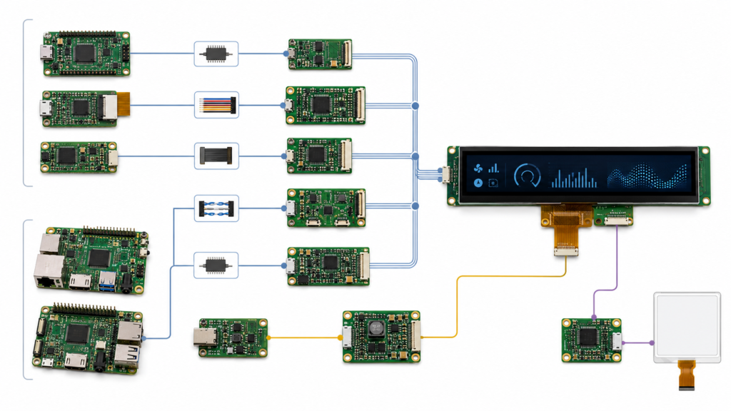
For broader interface background, see Common Interfaces in LCD Display Modules.
A common bar-display project begins with a host that normally generates standard monitor resolutions. The team then expects a bridge board or operating system to crop, stretch, rotate, or scale that image into the bar panel’s native timing.
Those functions should never be assumed. Depending on the architecture, rotation or scaling may be performed by the application, graphics framework, operating system, display controller, bridge firmware, or panel driver. Some configurations may support only a defined input mode and a defined panel output.
For Android-based systems, AOSP documentation recognizes displays ranging from long, thin aspect ratios to square formats, but applications and device implementations still need the appropriate aspect-ratio, size, rotation, density, and scaling configuration.[4]
Before selecting the panel, confirm:
If the design uses an HDMI source with a MIPI panel, follow a panel-specific compatibility review rather than treating the bridge as a passive adapter. RJY Display’s HDMI-to-MIPI controller board compatibility guide provides the detailed review sequence.
A bar LCD can be combined with capacitive touch when a suitable display-touch configuration is available, but touch is not carried automatically by the display video interface. The touch controller normally has its own power, reset, interrupt, and communication path.
The project must coordinate the touch active area, cover glass, controller, FPC, host interface, driver, coordinate system, and display orientation.
Android’s touch-device documentation explains that raw touch coordinates are mapped to display pixels and that orientation-aware touch input can be remapped when the display rotates.[5] This is particularly important on a long, narrow display because an incorrect axis swap or rotation can place input far from the visible control.
Touch validation should include:
A display image working correctly does not prove that the touch system is correctly integrated.
Brightness should be selected for the intended viewing environment rather than maximized without a system review. The appropriate requirement depends on ambient light, cover material, viewing angle, user distance, enclosure design, power budget, and thermal conditions.
The backlight must also be matched electrically. Confirm its input requirements, LED configuration, current control, enable logic, dimming method, and any thermal constraints. A controller board that supports one backlight configuration may not support another without circuit changes.
Evaluate the complete assembly at the intended brightness. Cover glass, printed borders, bonding material, surface treatments, and the enclosure opening can affect the appearance of the finished product.
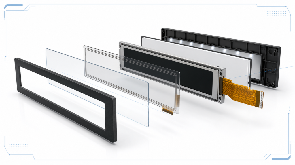
A bar display may fit the front opening while still conflicting with the internal structure. The rear frame, driver area, FPC, connector, touch tail, backlight components, or cable bend radius may occupy space needed by the main PCB or enclosure supports.
The mechanical review should cover:
| Mechanical Item | Review Question |
|---|---|
| Module outline | Does the complete assembly fit with realistic manufacturing tolerances? |
| Active-area alignment | Is the visible image centered correctly within the bezel opening? |
| FPC exit | Can the cable reach the connector without folding across a component or sharp edge? |
| Connector access | Can the connector be opened, closed, inspected, and serviced during assembly? |
| Support and adhesive | Are forces applied to approved structural areas rather than the active glass? |
| Cover glass | Do the outline, border, opening, adhesive area, and touch stack match the enclosure? |
| Thermal clearance | Is the display isolated from local heat sources and unintended mechanical stress? |
Review the display drawing and enclosure CAD together before finalizing tooling. Moving a connector or changing the housing after sampling may create a broader redesign than selecting a better-matched module earlier.
| Architecture | Appropriate When | Main Validation Scope |
|---|---|---|
| MCU or processor directly drives the LCD | The host exposes the required interface and can generate the native timing | Pinout, timing, framebuffer, driver, initialization, backlight, touch, and PCB routing |
| Embedded computing board drives the LCD | The product needs an application processor, operating system, networking, or peripheral control | Board-level interface implementation, BSP, panel driver, touch, application workload, power, and mechanics |
| Video bridge or LCD controller board | The source output and panel interface differ | Input mode, output timing, scaling, rotation, firmware, panel power, backlight, and touch path |
| External monitor-style assembly | The project benefits from separated display and host assemblies | Cables, retention, video identification, touch return path, power, mounting, and startup behavior |
The shortest component list is not always the lowest-risk architecture. A direct interface can reduce hardware, but it requires close control of the panel driver and board design. A controller-board route can simplify the host connection only when the board is confirmed for the actual panel and input mode.
RJY Display’s public product range provides several starting points for engineering review:
| Existing Product Path | Initial Evaluation Use |
|---|---|
| 4.58-inch bar TFT LCD | Review for compact embedded interfaces with a narrow mechanical envelope |
| 6.8-inch bar TFT LCD | Review for appliance or equipment layouts requiring a longer intermediate-size canvas |
| 6.9-inch bar LCD | Review for narrow embedded display systems using a compatible host architecture |
| 8.8-inch bar TFT LCD | Review for longer status, dashboard, or secondary-control interfaces |
| 11.65-inch bar LCD | Review for larger ultra-wide interface concepts |
| 12.3-inch bar TFT LCD | Review for larger embedded HMI layouts after current specifications are confirmed |
These links are product-discovery starting points, not compatibility approvals. Request the latest datasheet, mechanical drawing, pin definition, timing table, driver information, touch specification, and backlight requirements before selecting a sample.
When the core LCD platform is suitable, a project may evaluate changes around the existing module. The practical scope can include cover glass, touch integration, backlight, FPC, connector or interface coordination, controller board, firmware configuration, and mechanical structure.
This should not be interpreted as the ability to create any arbitrary bar-display size or pixel matrix from scratch. Feasibility depends on the available LCD platform, the proposed modification, engineering review, and the project requirements.
See the custom TFT LCD display guide for the broader development and RFQ process.
| Validation Area | Minimum Review |
|---|---|
| Image | Native resolution, timing, orientation, color, full-screen patterns, startup, sleep, and wake |
| UI | Normal workflow, alarms, long text, localization, animation, error screens, and boot states |
| Touch | Coordinates, rotation, edges, cover glass, noise exposure, gestures, and wake behavior |
| Interface | Signal configuration, cable or FPC, connector retention, firmware, and repeated restart |
| Backlight | Enable, dimming, brightness range used by the product, power behavior, and temperature |
| Mechanical assembly | Alignment, support, FPC routing, connector access, cover-glass fit, and enclosure tolerances |
| System operation | Voltage limits, interrupted power, application failure, peripheral loading, and long-duration use |
The approved production configuration should identify the LCD model, touch controller, board revision, firmware or BSP, cable, backlight circuit, application version, cover glass, and enclosure. A change to any of these items may require partial revalidation.
A useful engineering request should include:
RJY Display can review an existing bar LCD platform against your active-area, resolution, interface, touch, backlight, FPC, controller-board, firmware, cover-glass, and mechanical requirements.
Browse current bar LCD modules or send your UI, host-board, and enclosure requirements for engineering review.
A bar LCD display is a TFT LCD module with an elongated active area and pixel matrix. It may also be described as a bar-type, strip, stretched, or ultra-wide display, but these names do not define a standard interface, timing, connector, or mechanical outline.
No. Compare the active area, viewing area, module outline, resolution, aspect ratio, thickness, FPC position, connector, touch structure, and enclosure clearances. Displays with similar diagonal sizes can have substantially different physical proportions.
Only through a confirmed display or controller-board configuration. The HDMI source mode, panel interface, native timing, scaling, rotation, firmware, power, backlight, and touch path must all be verified for the actual panel.
There is no single best interface. SPI, RGB, MIPI DSI, LVDS, and controller-board routes fit different processors, resolutions, update requirements, cable arrangements, and software platforms. Choose the interface supported by both the actual host implementation and the selected panel.
It can when a suitable touch configuration is available for the selected module. The touch active area, cover glass, controller, FPC, host interface, driver, coordinate mapping, rotation, and operating environment must be reviewed separately from the display video interface.
Provide the application, maximum mechanical envelope, visible area, resolution or UI artwork, host board, interface, touch and cover-glass requirements, brightness and environment, FPC constraints, firmware needs, prototype quantity, expected annual demand, and available drawings or datasheets.
Share your display size, resolution, interface, brightness, touch requirement, controller board requirement, and application environment.
Continue reading related display technology guides and application references.
Talk to RJY’s engineering team for display matching, controller board review, and customization discussion.