¿Enfrenta un cuello de botella en su proyecto de pantalla integrada?
No permita que la integración compleja o los problemas de la cadena de suministro retrasen su tiempo de comercialización. Reserve una consulta gratuita con el equipo experto de RJY para obtener soporte personalizado en diseño y fabricación.
Cómo reemplazar un módulo TFT LCD descontinuado sin rediseñar todo el producto
Publicado:
13 min read → 1. Lectura de 13 minutos
Actualizado:
Un LCD TFT descontinuado puede crear un problema desproporcionado para un producto que por lo demás es estable. El equipo puede aún estar en producción, instalado en el campo, o se espera que siga siendo utilizable durante años, sin embargo, el módulo de pantalla original ya no está disponible a través de los canales normales.
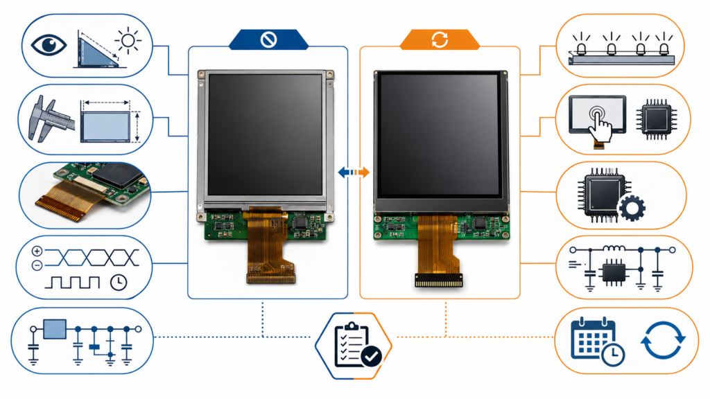
La reacción más rápida suele ser buscar otro LCD con el mismo tamaño diagonal y resolución. Ese enfoque rara vez es suficiente. Un reemplazo debe funcionar con el gabinete existente, la estructura de montaje, la placa principal, el sistema de alimentación, la interfaz de pantalla, el firmware, el circuito de retroiluminación, el controlador táctil y la interfaz de usuario. Un panel que parece equivalente en un catálogo puede requerir un nuevo cable, una placa adaptadora, un cambio de firmware, una modificación mecánica o una recalificación completa.
Por lo tanto, el objetivo no es encontrar una pantalla que simplemente se parezca al modelo descontinuado. Es identificar la vía de reemplazo de menor riesgo que preserve la mayor parte de la arquitectura del producto existente que sea práctica.
Primero, confirme qué significa “Descontinuado”
Antes de comenzar un rediseño, confirme el estado real del ciclo de vida del módulo original. “No disponible de nuestro distribuidor actual” no siempre es lo mismo que “ya no se fabrica”. El inventario puede haberse trasladado a otro canal autorizado, el modelo puede haber sido reemplazado por una revisión documentada, o el proveedor aún puede aceptar un pedido de producción final.
La terminología del ciclo de vida varía entre fabricantes. Texas Instruments, por ejemplo, distingue entre productos que no se recomiendan para nuevos diseños, productos en una fase de última compra y productos que están completamente obsoletos.[1] Este es un ejemplo de un sistema de ciclo de vida estructurado, no un cronograma universal para proveedores de LCD.
Solicite confirmación por escrito de:
El número de pieza y revisión exactos del fabricante
Si el producto está activo, restringido, en fase de última compra u obsoleto
Las fechas de pedido final y envío final, si corresponde
Cualquier sucesor recomendado por el fabricante
Si solo cambió un componente o se descontinuó el módulo completo
El inventario trazable restante y su historial de almacenamiento
Una última compra puede proteger la producción a corto plazo, pero no elimina la necesidad de un reemplazo calificado. El inventario restante puede ser insuficiente para el servicio de campo, la producción futura o una demanda inesperada.
Preserve la línea base de visualización original antes de buscar
Los mejores proyectos de reemplazo comienzan con una línea base técnica controlada. Si el módulo original se evalúa solo después de que se haya agotado el stock, el equipo de ingeniería puede descubrir que faltan dibujos importantes, archivos de firmware, muestras y registros de producción.
Conserve al menos una muestra dorada verificada de una unidad de producción en funcionamiento. Registre la etiqueta del módulo, la revisión, el código de fecha, la orientación del conector, el ensamblaje del cable, la posición de montaje, la imagen mostrada, el comportamiento de la retroiluminación, la respuesta táctil, la secuencia de inicio y las condiciones de funcionamiento.
El paquete de documentación debe incluir:
Hoja de datos y dibujo dimensional del módulo LCD original
Definición de pines del FPC o conector
Tabla de temporización de la pantalla
Información de la interfaz y formato de píxeles
Rieles de alimentación y requisitos de secuenciación de energía
Información de voltaje, corriente, habilitación y atenuación de la retroiluminación
Documentación del panel táctil y del controlador táctil
Páginas del esquema de la placa principal relacionadas con la pantalla
Código de inicialización de la pantalla, controlador, datos del árbol de dispositivos o firmware de la placa controladora
Muestra de producción aprobada y criterios de inspección de entrada
Si la documentación del fabricante original está incompleta, las mediciones de un sistema en funcionamiento pueden ayudar a establecer una línea base. Sin embargo, la medición debe complementar, no reemplazar, las especificaciones eléctricas y de temporización originales siempre que esos documentos estén disponibles.
Un LCD de reemplazo debe ser compatible con el sistema
El tamaño diagonal y la resolución son solo el comienzo de la equivalencia. El reemplazo debe revisarse en varios dominios de ingeniería.
Área de compatibilidad
Elementos a comparar
Riesgo si se pasa por alto
Óptico
Resolución, brillo, contraste, dirección de visión, comportamiento del color, área activa, polarizador
La pantalla funciona pero ya no cumple con los requisitos de legibilidad o interfaz de usuario
Características
Contorno, grosor, posición del área activa, bisel, puntos de montaje, salida del FPC, ubicación del conector
El módulo no se puede ensamblar en el gabinete existente
Eléctrico
Voltaje lógico, corriente, rieles de polarización, reinicio, habilitación, secuenciación, conexión a tierra
Sin imagen, funcionamiento inestable o daño a los componentes
Interfaz y temporización
Tipo de interfaz, número de canales o carriles, reloj de píxeles, blanking, polaridad, formato de píxeles, inicialización
El host no puede controlar el panel correctamente
Retroiluminación
Configuración del LED, voltaje directo, corriente, PWM, polaridad de habilitación, carga térmica
Brillo incorrecto, sobrecarga del controlador, parpadeo o sobrecalentamiento
Táctil
Tipo táctil, controlador, interfaz de comunicación, firmware, mapeo de coordenadas, estructura de la cubierta
El video funciona pero el táctil no está disponible o está desalineado
Software y firmware
Controlador de panel, comandos de inicialización, orientación, comportamiento de inicio, configuración de la placa controladora
Pantalla en blanco, colores incorrectos, orientación incorrecta o falla en el arranque
Ciclo de vida y producción
Estado del proveedor, control de revisiones, demanda esperada, documentación, notificación de cambios, muestras de validación
El reemplazo genera otro problema de suministro poco después de la calificación
Esta visión sistémica explica por qué dos módulos con idéntico tamaño y resolución pueden no ser intercambiables. La pantalla es un subsistema que depende de componentes eléctricos, ópticos, mecánicos y de software.
Factores de compatibilidad para seleccionar un reemplazo de pantalla TFT LCD descontinuada
Qué significan Forma, Ajuste y Función para un reemplazo de LCD
“Forma, ajuste y función” es una abreviatura útil, pero cada categoría necesita una definición específica para pantallas.
Forma: ¿Puede el módulo ocupar el mismo espacio físico?
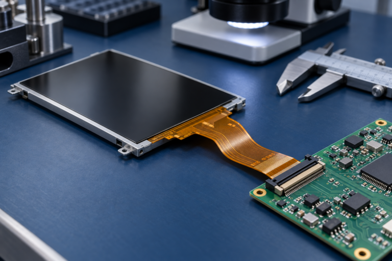
La forma incluye las dimensiones exteriores, el contorno del vidrio y el marco, el grosor del módulo, la posición del área activa, el ancho del bisel, el método de montaje, la dirección del FPC, la posición del conector, el contorno del panel táctil y la geometría del vidrio de cubierta. Incluso una pequeña diferencia puede afectar las ubicaciones de los tornillos, la presión del gabinete, el sellado, el enrutamiento de cables o la alineación visible entre el LCD y la ventana frontal.
Ajuste: ¿Puede conectarse al producto existente?
El ajuste incluye más que la conexión física del conector. La asignación de pines, la orientación del contacto, el voltaje lógico, los rieles de alimentación, el circuito de retroiluminación, la interfaz de pantalla, la polaridad de la señal, la conexión a tierra y la sincronización deben ser compatibles con el sistema anfitrión.
Un conector con la misma cantidad de pines puede tener una definición de pines completamente diferente. Conectar un módulo no verificado puede colocar un voltaje de alimentación en un pin de señal o invertir la ubicación de pares diferenciales.
Función: ¿El producto final se comporta según lo previsto?
La función incluye estabilidad de imagen, orden de colores, brillo, comportamiento de visualización, rendimiento de actualización, tiempo de inicio, respuesta táctil, orientación, atenuación, comportamiento en reposo y operación en el entorno previsto del producto.
Un reemplazo no se ha calificado simplemente porque muestra una imagen de prueba en el banco. Debe satisfacer las funciones que importan en el equipo real.
Cinco vías prácticas de reemplazo
La ruta de menor riesgo depende del inventario disponible, la vida útil restante del producto, la demanda anual, las diferencias técnicas y la cantidad de rediseño que el OEM pueda aceptar.
Ruta de reemplazo
Mejor uso
Ventaja principal
Principal limitación
Stock restante verificado
Demanda de producción o servicio restante corta
Sin rediseño inmediato
Inventario finito, almacenamiento, trazabilidad y riesgo de falsificación
Sucesor designado por el fabricante
Existe un módulo de próxima generación documentado
Puede preservar parte de la intención de diseño original
El sucesor no significa automáticamente compatible de forma directa
Módulo de catálogo compatible
Un módulo actual coincide estrechamente con el original
Menor esfuerzo de desarrollo que una personalización más profunda
Puede requerir cambios en cable, firmware, retroiluminación o mecánicos
Módulo semipersonalizado basado en una plataforma existente
El módulo disponible es cercano pero necesita cambios en FPC, retroiluminación, táctil, vidrio de cubierta, interfaz o estructura
Puede preservar más del producto existente sin crear un nuevo tamaño de LCD desde cero
Requiere revisión de ingeniería, costo de desarrollo, cantidad mínima de pedido y validación
Solución de controlador o placa adaptadora
La nueva interfaz o sincronización del panel no puede ser manejada directamente por el anfitrión existente
Puede preservar la placa principal del anfitrión y la arquitectura de software
Añade consideraciones de espacio, energía, firmware, integridad de señal y suministro
Si ninguna de estas rutas puede cumplir con los requisitos del producto de manera segura, un rediseño más amplio puede ser más responsable que forzar un panel inadecuado en la arquitectura antigua.
Rutas de reemplazo para un módulo de pantalla TFT LCD industrial obsoleto
Cuándo una pantalla semi-personalizada es la mejor opción
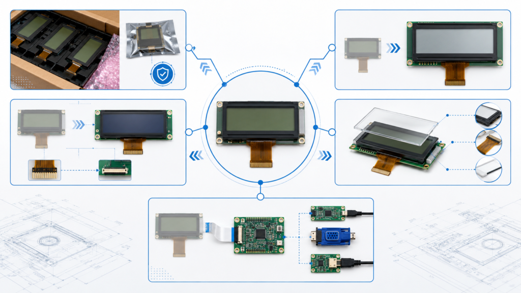
Una solución semipersonalizada suele ser útil cuando una plataforma de pantalla actual está técnicamente cerca del módulo descontinuado pero no cumple con todos los requisitos del sistema.
Las áreas de modificación práctica pueden incluir:
Longitud, dirección o disposición de pines del FPC
Posición del conector
Configuración de retroiluminación o objetivo de brillo
Integración táctil capacitiva o resistiva
Contorno del vidrio de cubierta y coordinación con el panel frontal
Coordinación de interfaz o placa controladora
Adaptación de firmware
Estructura mecánica alrededor del módulo existente
Este enfoque no debe describirse como la creación de un nuevo tamaño de LCD arbitrario desde cero. El punto de partida práctico es un módulo de pantalla existente cuyas características ópticas y eléctricas centrales sean suficientemente cercanas al requisito original.
Cuándo una placa controladora puede reducir el rediseño
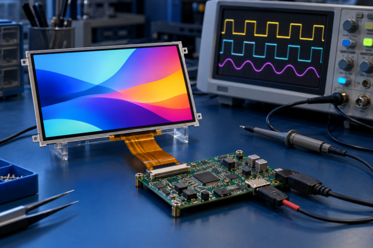
Una placa controladora o adaptadora puede ser útil cuando la pantalla de reemplazo utiliza una interfaz diferente, requiere una sincronización distinta o no puede conectarse directamente a la placa anfitriona heredada.
Por ejemplo, una salida de sistema existente puede necesitar convertirse para un panel que utilice LVDS, MIPI DSI, eDP, HDMI u otra interfaz. La ruta del controlador aún debe calificarse para resolución, sincronización, formato de píxeles, alimentación, retroiluminación, táctil, firmware y comportamiento del sistema operativo.
MIPI DSI ilustra por qué el nombre de la interfaz por sí solo es insuficiente. MIPI define DSI como una interfaz de alta velocidad entre un procesador anfitrión y un módulo de pantalla, mientras que su operación puede involucrar configuración D-PHY, comandos de pantalla y requisitos específicos del panel.[2] La documentación de DSI de NXP también distingue entre modos de video y comando, y muestra que la configuración de carriles, sincronización, alimentación, reinicio y control de retroiluminación son parte de la puesta en marcha del panel.[3]
Una solución de placa controladora puede reducir los cambios en el producto principal solo cuando la placa adicional en sí misma puede ser alojada. Revise:
Espacio disponible en PCB y gabinete
Compatibilidad de interfaz de entrada y salida
Consumo de energía y efecto térmico
Comportamiento de arranque y activación
Propiedad del firmware y proceso de actualización
Integración de retroiluminación y táctil
Longitud del cable e integridad de la señal
Disponibilidad a largo plazo de la placa controladora
La categoría de módulo de computación de Guía de interfaz LCD proporciona información adicional sobre interfaces de pantalla comunes.
Riesgos de reemplazo específicos de la interfaz
Paneles RGB o TTL
Los paneles RGB pueden exponer muchas señales de datos y temporización en paralelo. El reemplazo debe coincidir con la profundidad de color compatible, el reloj de píxeles, el comportamiento de sincronización, la lógica de habilitación de datos, el nivel de voltaje y la asignación de pines. Una resolución similar no garantiza una temporización idéntica.
Paneles LVDS
Para LVDS, verifique la configuración de canal único o dual, la asignación de bits, la profundidad de color, el reloj de píxeles, la asignación del conector, la polaridad y la alimentación del panel. Diferentes convenciones de asignación LVDS pueden producir colores incorrectos incluso cuando aparece una imagen.
Paneles MIPI DSI
Los reemplazos MIPI DSI requieren revisar el número de carriles, la velocidad de carril, el modo de video o comando, el formato de píxeles, los comandos de inicialización, la temporización D-PHY, el comportamiento de reinicio, la secuencia de alimentación y la asignación del conector. El IC controlador del panel y los datos de inicialización pueden ser tan importantes como su resolución.
Paneles eDP
Para eDP, revise el número de carriles, la velocidad de enlace, la alimentación del panel, el comportamiento del canal auxiliar, el control de retroiluminación, la temporización, la definición del conector y la compatibilidad con el host. La apariencia de un conector tipo laptop no establece equivalencia.
Paneles SPI y MCU
Las pantallas más pequeñas conectadas por SPI o MCU pueden depender en gran medida del IC controlador, el conjunto de comandos, la secuencia de inicialización, la biblioteca, la estrategia del búfer de cuadros y el software del host. Un reemplazo que utilice otro IC controlador puede generar un cambio de software mayor de lo esperado.
Un proceso de calificación estructurado
1. Definir los Requisitos No Negociables
Separe las restricciones fijas de las preferencias negociables. La abertura del gabinete, la interfaz del host, la alimentación disponible, la resolución de la interfaz de usuario, el método táctil y el entorno operativo pueden ser fijos. El brillo, los detalles del vidrio de cubierta, la construcción del cable o los soportes de montaje pueden ofrecer más flexibilidad.
2. Examinar Módulos Candidatos
Utilice el paquete de especificaciones original para eliminar candidatos con conflictos mecánicos, eléctricos, de interfaz o de ciclo de vida evidentes. No solicite muestras únicamente porque el título del catálogo parezca similar.
3. Crear una Matriz de Diferencias
Compare el módulo original y el candidato línea por línea. Marque cada parámetro como idéntico, compatible con verificación, adaptable o incompatible. Esto hace visible el alcance real del desarrollo antes de comprometer costos de herramientas o muestras.
4. Seleccionar la Estrategia de Adaptación
Decida si las brechas pueden resolverse mediante un FPC, cable, placa controladora, circuito de retroiluminación, configuración táctil, vidrio de cubierta, firmware, soporte mecánico u otro cambio a nivel de módulo.
5. Probar Muestras de Ingeniería
Pruebe el candidato en la arquitectura real del producto. Una placa de evaluación genérica puede confirmar el funcionamiento básico del panel, pero no demuestra compatibilidad con el host de producción, la fuente de alimentación, el gabinete, el cable, el sistema táctil o el software.
6. Realizar Validación Apropiada para la Aplicación
El plan de validación debe reflejar los requisitos reales del equipo y cualquier norma aplicable al producto terminado. Dependiendo de la aplicación, esto puede incluir funcionamiento operativo, comportamiento de inicio, pruebas térmicas, inspección de brillo y visual, rendimiento táctil, estabilidad de señal, ciclos de alimentación, ajuste mecánico y evaluación ambiental.
7. Controlar el Cambio de Producción
Una vez aprobado, documente el nuevo número de pieza, planos, firmware, cable, instrucciones de ensamblaje, criterios de inspección, muestra aprobada, nivel de revisión y fecha efectiva de producción. No permita que el reemplazo entre en producción como una sustitución de compra no documentada.
Matriz de validación de reemplazo
Etapa de Validación
Ejemplos de Verificaciones
Evidencia de Aprobación
Revisión de documentación
Hoja de datos, plano, asignación de pines, temporización, interfaz, ciclo de vida
Contorno, alineación del área activa, enrutamiento del FPC, tensión de montaje
Muestra de ensamblaje y plano aprobados
Función del sistema
Arranque, suspensión, activación, orientación, interfaz de usuario, asignación táctil
Resultado de prueba funcional a nivel de producto
Validación de aplicación
Temperatura, duración operativa, ciclos de alimentación, legibilidad, requisitos ambientales
Informe de validación aprobado basado en requisitos del producto
Control de producción
Revisión, inspección, firmware, proveedor aprobado y trazabilidad
Lista de materiales liberada y registro de cambios
Qué enviar al solicitar una revisión de reemplazo
Una solicitud de cotización completa permite al proveedor evaluar el alcance real de la adaptación, en lugar de cotizar una pantalla no relacionada con una especificación principal similar.
Prepare:
Fabricante original del LCD y número de pieza completo
Hoja de datos, plano y definición de pines del FPC
Fotografías claras del módulo y el conector
Una muestra funcional, si está disponible
Tamaño de pantalla, resolución, área activa y requisito de brillo
Información de interfaz, temporización, voltaje y retroiluminación
Detalles del panel táctil y del controlador táctil
Información del host o placa controladora existente
Espacio mecánico disponible y plano del gabinete
Entorno operativo y requisitos aplicables del producto
Motivo del reemplazo
Cantidad de muestra requerida
Demanda anual y ciclo de vida restante del producto
Fechas objetivo de calificación y producción
Si la documentación importante no está disponible, indíquelo claramente. El proyecto puede requerir ingeniería inversa o mediciones adicionales, y la compatibilidad puede no ser confirmable solo con fotografías.
Planifique la obsolescencia antes de que la próxima pantalla sea descontinuada
La gestión de obsolescencia debe continuar después de que se libere el reemplazo. IEC 62402:2019 describe la gestión de obsolescencia como un proceso de ciclo de vida que incluye política, planificación, reducción de riesgos, selección de resolución, implementación y mejora del rendimiento.[4]
Para productos dependientes de pantallas, las medidas prácticas incluyen mantener registros precisos de piezas aprobadas, archivar firmware y documentación del panel, conservar una muestra de referencia, monitorear avisos de cambio del proveedor, registrar alternativas aceptables y revisar el riesgo del ciclo de vida antes de que un producto entre en producción a largo plazo.
Algunos proveedores de componentes electrónicos publican procesos formales de cambio y descontinuación de productos. Por ejemplo, TI describe estados de ciclo de vida y un proceso de retirada con períodos de último pedido y entrega final.[5] Estas fechas no deben generalizarse a todos los proveedores de LCD, pero ilustran por qué los canales de notificación documentados son importantes.
Cómo RJY Display apoya los proyectos de reemplazo de LCD TFT
RJY Display respalda la revisión técnica de módulos TFT LCD, placas controladoras y la personalización de pantallas basada en plataformas de módulos existentes. Para un proyecto de pantalla descontinuada, la dirección práctica puede implicar seleccionar un módulo actual, comparar las diferencias eléctricas y mecánicas, y coordinar los cambios relevantes en torno a la pantalla.
Dependiendo de la viabilidad del proyecto, la discusión puede incluir vidrio de cubierta, retroiluminación, panel táctil, interfaz, FPC, placa controladora, firmware y coordinación de la estructura mecánica. Esto no significa que cada LCD descontinuado pueda reproducirse exactamente o que se pueda desarrollar económicamente un tamaño de panel completamente nuevo desde cero.
El objetivo es identificar una ruta de reemplazo técnicamente viable con un alcance de validación definido.
Solicite una revisión de reemplazo de un LCD descontinuado
Envíe a RJY Display el número de pieza original del LCD, la hoja de datos, la definición de pines, fotografías, información de la interfaz del host, el entorno operativo, la demanda anual y el cronograma objetivo. La revisión técnica puede comparar los módulos TFT LCD disponibles y determinar si se debe evaluar un módulo estándar, una pantalla semipersonalizada, un cable, una placa controladora, una adaptación de firmware o un rediseño más amplio.
¿Puede un LCD con el mismo tamaño y resolución reemplazar un módulo descontinuado?
No automáticamente. El reemplazo también debe coincidir o adaptarse al contorno mecánico, área activa, conector, definición de pines, voltaje, interfaz, temporización, retroiluminación, sistema táctil, firmware y entorno operativo.
¿Cuál es el requisito más importante al seleccionar un TFT LCD de reemplazo?
El requisito más importante es la compatibilidad con el sistema completo del producto. Ninguna especificación individual confirma la equivalencia; los requisitos mecánicos, eléctricos, ópticos, de interfaz, software, táctiles y de ciclo de vida deben revisarse en conjunto.
¿Puede una placa controladora evitar rediseñar la placa base existente?
A veces. Una placa controladora o adaptadora puede convertir la salida del host existente para un nuevo panel, pero la solución aún debe verificarse en cuanto a espacio, alimentación, temporización, firmware, retroiluminación, táctil, integridad de la señal y disponibilidad a largo plazo.
¿Puede un LCD personalizado reproducir exactamente cualquier pantalla descontinuada?
No siempre. El enfoque más práctico suele ser comenzar con una plataforma LCD existente y personalizar los elementos circundantes relevantes, como el FPC, la retroiluminación, el panel táctil, el vidrio de cubierta, la interfaz, la placa controladora, el firmware o la estructura mecánica.
¿Qué información se necesita para una revisión de reemplazo de LCD descontinuado?
Proporcione el número de pieza original, la hoja de datos, el dibujo, la definición de pines, la temporización, la interfaz, los datos de alimentación y retroiluminación, la información táctil, los detalles de la placa host, fotografías, una muestra de trabajo si está disponible, el entorno operativo, la demanda anual y el cronograma del proyecto.
¿Debe un OEM comprar todo el stock restante después de recibir un aviso de descontinuación?
Solo después de revisar la demanda pronosticada, los requisitos de servicio en campo, las condiciones de almacenamiento, la trazabilidad, la autenticidad, la exposición de efectivo y el tiempo necesario para calificar un reemplazo. Una compra de última hora puede proporcionar cobertura temporal, pero no sustituye una estrategia de reemplazo.
¿Aún no sabe qué pantalla se adapta a su proyecto?
Hable con el equipo de ingeniería de RJY para obtener asesoramiento sobre compatibilidad de pantallas, revisión de placas controladoras y discusión sobre personalización.