Stehen Sie bei Ihrem Embedded-Display-Projekt vor einer Herausforderung?
Lassen Sie nicht komplexe Integration oder Lieferkettenprobleme Ihre Markteinführung verzögern. Vereinbaren Sie eine kostenlose Beratung mit dem RJY-Expertenteam für maßgeschneiderte Design- und Fertigungsunterstützung.
Kundenspezifisches MIPI-TFT-LCD-Display: Integrationsleitfaden für OEMs
Veröffentlicht:
17 Minuten Lesezeit
Aktualisiert:
A Kundenspezifisches MIPI-TFT-LCD-Display Das Projekt ist nicht abgeschlossen, indem ein Panel mit “MIPI” im Schnittstellenfeld ausgewählt wird. Das Displaymodul und der Host müssen hinsichtlich der DSI-Implementierung, Lane-Konfiguration, nativen Timing, Pixelformat, Initialisierungsbefehlen, Einschaltsequenz, Reset-Verhalten, Steckverbinder, Firmware, Hintergrundbeleuchtung, Touch-System und mechanischer Struktur übereinstimmen.
Das Wort “kundenspezifisch” benötigt ebenfalls eine praktische Abgrenzung. Für die meisten OEM-Projekte beginnt der steuerbare Weg mit einem bestehenden MIPI-TFT-LCD-Modul. Das Projekt kann dann Änderungen rund um diese Plattform bewerten, wie z. B. Abdeckglas, Touchscreen, Hintergrundbeleuchtung, FPC, Steckverbinder-Koordination, Controller-Board, Firmware-Konfiguration und mechanische Integration.
Dieser Leitfaden erläutert, wie entschieden werden kann, ob MIPI DSI zum Produkt passt, wie ein Panel mit dem tatsächlichen Host abgeglichen wird und welche Informationen kontrolliert werden sollten, bevor Muster oder Produktionswerkzeuge freigegeben werden.
MIPI DSI ist eine schnelle serielle Schnittstelle zwischen einem Host-Prozessor und einem Displaymodul. Die MIPI Alliance beschreibt sie als eine Schnittstelle, die entwickelt wurde, um die Display-Leistung zu unterstützen und gleichzeitig die Pin-Anzahl, den Stromverbrauch und die elektromagnetische Störung im Vergleich zu breiteren parallelen Verbindungen zu reduzieren.[1]
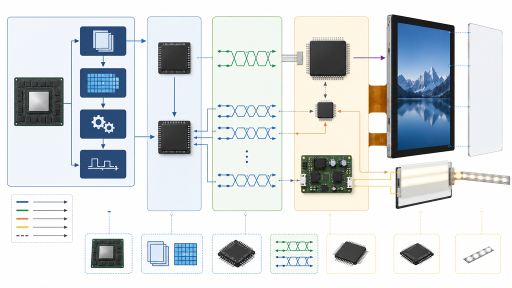
Ein typisches eingebettetes MIPI-Display-System umfasst mehr als nur das DSI-Kabel oder die FPC:
Systemelement
Funktion
Projektfrage
Anwendungsprozessor oder MCU
Erzeugt die Benutzeroberfläche und den Framebuffer
Kann der tatsächliche Prozessor und die Platine den erforderlichen DSI-Modus und das Timing des Panels erzeugen?
Display-Controller
Liest Pixeldaten und erzeugt den Display-Stream
Unterstützt er die Auflösung, das Pixelformat, die Aktualisierungsanforderung und die Speicherbandbreite?
MIPI-DSI-Host
Verpackt Display-Daten und Steuerverkehr für die DSI-Verbindung
Welche Lane-Anzahlen, Betriebsmodi, Takte und Paketformate sind implementiert?
D-PHY
Stellt die physischen Takt- und Daten-Lanes bereit
Kann die Platine die erforderliche Lane-Rate und elektrische Konfiguration erzeugen?
TFT-LCD-Modul
Empfängt den Stream und zeigt das Bild an
Welche nativen Timing-, Treiber-IC-, Initialisierungs-, Spannungs-, Pinbelegungs- und Hintergrundbeleuchtungsanforderungen bestehen?
Panel-Treiber oder Firmware
Steuert Strom, Reset, Initialisierung, Timing, Schlaf, Aufwachen und Anzeigezustand
Wird das genaue Panel im Bootloader, Kernel, BSP oder in der MCU-Firmware unterstützt?
Touch und Hintergrundbeleuchtung
Bieten Benutzereingabe und Beleuchtung
Welche separaten Schnittstellen, Treiber, Leistungsschaltungen und Steuersignale sind erforderlich?
Die Kompatibilität muss über diesen gesamten Pfad hinweg hergestellt werden. Eine kompatible Steckverbinderform oder eine passende Auflösung ist nicht ausreichend.
MIPI-DSI-Displayarchitektur vom Anwendungsprozessor und D-PHY bis zum TFT-LCD-Modul
Was bedeutet “Kundenspezifisches MIPI-Display”?
Ein kundenspezifisches MIPI-Display wird für verschiedene Projektumfänge verwendet. Eine frühzeitige Trennung verhindert, dass eine RFQ als Anfrage für eine vollständig neue LCD-Plattform interpretiert wird.
Projekttyp
Praktischer Umfang
Hauptentwicklungsarbeit
Standard-MIPI-Modul
Ein vorhandenes LCD wird ohne physische Änderung verwendet
Host-Kompatibilität, Panel-Treiber, Kabel, Stromversorgung, Hintergrundbeleuchtung, Touch und Validierung
Vorhandenes Modul mit umgebender Anpassung
Das Kern-LCD bleibt erhalten, während Touch, Abdeckglas, Hintergrundbeleuchtung, FPC, Steckverbinder-Koordination, Firmware oder Mechanik angepasst werden
Kontrollierte Zeichnungen, Werkzeuge, Muster, Firmware, Montage und Systemvalidierung
MIPI-Modul mit Controller- oder Bridge-Board
Eine Platine wandelt die erforderliche DSI-Ausgabe des Panels um oder erzeugt sie
Eingabemodus, Ausgabe-Timing, Panel-Initialisierung, Stromversorgung, Hintergrundbeleuchtung, Touch, Firmware und Verkabelung
Anfrage für eine neue LCD-Plattform
Die angeforderte Größe, Pixelmatrix oder Kern-Panel-Architektur ist in keinem vorhandenen Modul verfügbar
Separate Machbarkeits-, Entwicklungs-, Volumen-, Qualifizierungs- und Lebenszyklusprüfung
Der praktische Anpassungsweg von RJY Display beginnt mit einem vorhandenen Displaymodul. Machbare Projektarbeiten können Abdeckglas, Touchscreen, Hintergrundbeleuchtung, FPC, Schnittstellenkoordination, Controller-Board, Firmware und mechanische Struktur umfassen. Dies sollte nicht als uneingeschränkte Entwicklung einer neuen LCD-Größe oder -Auflösung dargestellt werden.
Wann passt MIPI DSI zu einem eingebetteten Produkt?
MIPI DSI kann eine gute Wahl sein, wenn der tatsächliche Prozessor einen unterstützten DSI-Host bereitstellt, das Produkt eine kurze interne Displayverbindung aufweist und das Entwicklungsteam den Panel-Treiber und die System-Firmware kontrollieren kann.
Es kann geeignet sein für:
Kompakte eingebettete Produkte mit begrenztem Steckverbinder- und PCB-Platz
Anwendungsprozessor- oder MCU-Plattformen mit dokumentiertem DSI-Host
Displays, die eine höhere Pixeldatenrate erfordern, als der ausgewählte SPI-Pfad der MCU praktisch bereitstellen kann
Android-, Linux- oder RTOS-Systeme, in denen das Panel in die kontrollierte Softwareplattform integriert werden kann
Runde, quadratische, Hochformat- oder Balkendisplays, deren native Timing vom Host unterstützt wird
Produkte, bei denen Prozessor und Display innerhalb derselben kontrollierten Baugruppe verbleiben
MIPI ist nicht automatisch die beste Wahl, wenn:
Der Host die erforderlichen DSI-Lanes oder Betriebsmodi nicht bereitstellt
Das Softwareteam den Panel-Treiber nicht implementieren oder warten kann
Das Display sich wie ein austauschbarer externer Monitor verhalten muss
Die Verbindung eine Kabelarchitektur erfordert, die besser durch eine andere Schnittstelle bedient wird
Die UI-Arbeitslast einfacher über SPI, RGB, LVDS oder einen anderen vorhandenen Weg abgewickelt werden kann
Das vorhandene Produkt bereits eine validierte Schnittstelle besitzt und es keinen technischen Grund für eine Änderung gibt
Die richtige Wahl folgt den Anforderungen an Host, Display, Software, Gehäuse, Kabel, Leistung und Lebenszyklus. Sie sollte nicht auf der Annahme basieren, dass MIPI moderner und daher universell besser ist.
Beginnen Sie mit der tatsächlichen Host-Platine, nicht mit dem SoC-Datenblatt
Ein Prozessor-Datenblatt kann zeigen, dass die SoC-Familie einen MIPI-DSI-Controller enthält. Das beweist nicht, dass eine bestimmte Steuerplatine die erforderlichen Lanes, Steckverbinder, Spannungen, Takte, GPIOs, Firmware oder den Panel-Treiber bereitstellt.
Vor dem Vergleich von Displays sind zu erfassen:
Exaktes Prozessor- und Board-Modell
Board-Revision und Schaltplaninformationen
Anzahl der physisch verlegten DSI-Ports und Daten-Lanes
Board-Steckverbinder und Pin-Definition
Unterstützte DSI-Betriebsmodi
Maximale unterstützte Lane-Rate für diese Implementierung
Verfügbare Panel-Stromversorgungsschienen
Reset-, Enable-, Tearing-Effect- und Hintergrundbeleuchtungs-Steuer-GPIOs
Betriebssystem, Kernel, BSP, Bootloader oder MCU-SDK-Version
Vorhandene Panel-Treiber und dokumentierte Einschränkungen
Die Host-Prüfung sollte auf Board-Ebene durchgeführt werden. Ein für das SoC aufgeführtes Merkmal kann auf dem fertigen Board nicht verfügbar sein, weil die Pins nicht verlegt wurden, mit einer anderen Funktion geteilt werden oder im aktuellen BSP nicht unterstützt werden.
Kompatibilitätsprüfung 1: Lane-Anzahl und physische Implementierung
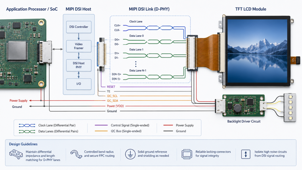
Eine MIPI-DSI-Verbindung enthält normalerweise eine Clock-Lane und eine oder mehrere Daten-Lanes. Die genaue Anzahl, die das Panel unterstützt, sowie die Anzahl, die der Host bereitstellt, müssen bestätigt werden.
Lane-Element
Was zu bestätigen ist
Host-Lane-Fähigkeit
Anzahl der auf der tatsächlichen Platine implementierten und von der Software unterstützten Daten-Lanes
Panel-Lane-Anforderung
Unterstützte oder erforderliche Lane-Anzahl im aktuellen Panel-Datenblatt
Lane-Reihenfolge
Zuordnung von Clock- und Daten-Lanes zwischen Host-Steckverbinder und Panel-FPC
Polaritätsbehandlung
Ob die Implementierung und Firmware eine erforderliche Lane-Polaritätskonfiguration zulassen
Virtueller Kanal
Die vom Host und Peripheriegerät erwartete Konfiguration des virtuellen Kanals
Steckverbinder und FPC
Pin-Definition, Kontaktorientierung, Rastermaß, Masseplatzierung und kontrollierte Leitungsführung
Die Linux-Dokumentation für MIPI-DSI-Device-Tree stellt den DSI-Host und seine angeschlossenen Peripheriegeräte als Bus dar und veranschaulicht, dass das Panel ein konfiguriertes Peripheriegerät und keine passive Gruppe differenzieller Leitungen ist.[4]
Eine Adapter-FPC kann die physische Pin-Verdrahtung ändern, kann jedoch fehlende DSI-Lanes nicht erzeugen oder einen nicht unterstützten DSI-Modus, eine nicht unterstützte Lane-Rate, ein nicht unterstütztes Timing oder eine nicht unterstützte Firmware-Implementierung korrigieren.
MIPI-DSI-Clock-Lane, Daten-Lanes, Steckverbinder, FPC, Stromversorgung, Reset und Hintergrundbeleuchtungsverbindungen
Kompatibilitätsprüfung 2: Lane-Rate und Pixel-Durchsatz
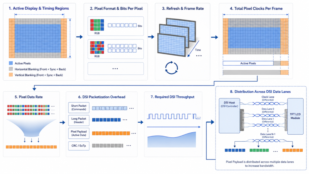
Die aktive Auflösung ist nur eine Eingangsgröße für die erforderliche Datenrate. Die technische Berechnung muss auch Pixelformat, Bildwiederholrate, Blanking-Timing, Paket-Overhead, ausgewählte Lane-Anzahl und den unterstützten Betriebsbereich von Host und Panel berücksichtigen.
Als erste Screening-Beziehung:
Aktive Pixel-Nutzlast ≈ aktive Breite × aktive Höhe × Bildwiederholrate × Bits pro Pixel
Dies ist nicht die endgültige D-PHY-Konfiguration, da Blanking-Intervalle und Protokoll-Overhead in der aktiven Pixel-Nutzlast nicht enthalten sind. Der native Pixeltakt muss aus dem vollständigen horizontalen und vertikalen Timing berechnet werden.
Das MIPI-DSI-Implementierungsbeispiel von NXP berechnet den Pixeltakt aus den aktiven Abmessungen, Synchronisationsbreiten, Porches und der Bildwiederholrate. Anschließend wird ein High-Speed-Bittakt gefordert, der für den Pixeltakt, die Ausgabebits pro Pixel und die ausgewählte Anzahl von Daten-Lanes ausreichend ist.[3]
Datenraten-Eingabe
Warum er wichtig ist
Aktive Breite und Höhe
Definieren der sichtbaren Pixel-Nutzlast
Horizontales und vertikales Blanking
Erweiterung des vollständigen Timings über das aktive Bild hinaus
Bildwiederholfrequenz
Ändert, wie oft ein vollständiges Bild übertragen werden muss
Pixelformat
Ändert die Anzahl und Verpackung der übertragenen Farbbits
Lane-Anzahl
Verteilt die übertragenen Daten auf die implementierten Lanes
Panel- und Host-Grenzen
Definieren, ob die berechnete Konfiguration innerhalb des unterstützten Betriebsbereichs liegt
Genehmigen Sie kein Panel aufgrund einer Aussage wie “das Board unterstützt 1080p”. Ein Board kann einen Standard-Monitor-Modus unterstützen, während es das native Timing oder die Lane-Konfiguration eines Hochformat-, Quadrat-, Rund- oder Balken-MIPI-Panels nicht erzeugen kann.
Pixel-Timing, Blanking, Pixelformat und DSI-Lane-Faktoren im MIPI-Display-Durchsatz
Kompatibilitätsprüfung 3: Native Timing
Ein MIPI-Panel hat weiterhin ein natives Anzeige-Timing. Die Auflösung definiert nicht den Pixeltakt, die Synchronisationsbreiten, Porches, das Aktualisierungsverhalten, die Signalpolarität oder die vollständige Zeilen- und Bildstruktur.
Timing-Element
Erforderliche Nachweise
Mögliches Symptom bei Fehlfunktion
Aktive Breite und Höhe
Aktuelles Panel-Datenblatt
Beschnittenes, leeres oder nicht unterstütztes Bild
Pixel-Takt
Mindest-, typische und maximale Werte, sofern angegeben
Instabiles Bild, keine Synchronisation oder Artefakte
Horizontale Porches und Synchronisation
Vollständige Zeilen-Timing-Tabelle
Verschobenes, verzerrtes oder fehlendes Bild
Vertikale Porches und Synchronisation
Vollständige Bild-Timing-Tabelle
Rollen, Flackern oder falsches Bildverhalten
Bildwiederholfrequenz
Unterstützter Panel-Bereich und Zielsystemmodus
Nicht unterstütztes Timing oder inkonsistente visuelle Aktualisierungen
Signalpolarität
Panel-Spezifikation und Host-Konfiguration
Kein verwertbares Bild oder instabile Ausgabe
Der Anwendungshinweis von NXP besagt, dass Timing-Parameter programmiert werden müssen, um der Display-Spezifikation zu entsprechen, und identifiziert separat aktive Auflösung, Pixeltakt, Synchronisation, Front Porch, Back Porch und Pulsbreite.[3]
Fordern Sie die native Timing-Tabelle an, bevor Sie das Host-Board oder PCB-Design festlegen. Ein Auflösungsfeld auf der Produktseite reicht für die Firmware-Integration nicht aus.
Kompatibilitätsprüfung 4: DSI-Betriebsmodus und Pixelformat
Host und Panel müssen dieselbe praktikable DSI-Betriebskonfiguration unterstützen. Zu bestätigende Punkte umfassen:
Videomodus oder Befehlsmodus
Burst- oder anwendbares Nicht-Burst-Verhalten
Unterstütztes Pixelformat und Farbdaten-Packing
Kontinuierliches oder nicht-kontinuierliches Taktverhalten, sofern zutreffend
Anforderungen an die Low-Power-Befehlsübertragung
Anforderungen an das Tearing-Effect-Signal, sofern verwendet
Anzeigedaten- und Steuerbefehlssequenz
Der MIPI Display Command Set bietet standardisierte Funktionen für Display-Einrichtung, Steuerung, Test und Datenübertragung.[2] Ein gemeinsamer Befehlsstandard beweist jedoch nicht, dass zwei Panels eine identische Initialisierungssequenz oder Standardkonfiguration verwenden. Der exakte Treiber-IC und die Panel-Dokumentation bleiben maßgeblich.
Ein Host, der den MIPI-DSI-Videomodus unterstützt, ist nicht automatisch mit einem Panel oder Modul kompatibel, das für einen anderen Modus konfiguriert ist. Dies muss vor Beginn der Firmware-Arbeiten überprüft werden.
Kompatibilitätsprüfung 5: Treiber-IC und Initialisierungsbefehle
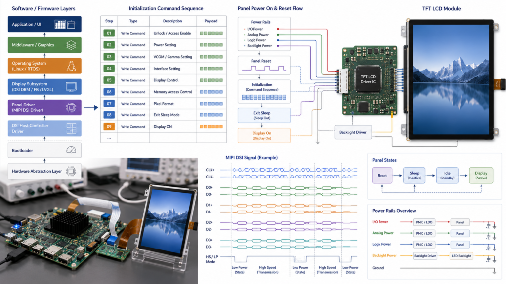
Viele MIPI-TFT-Module erfordern eine geordnete Initialisierungssequenz, bevor sie ein Bild korrekt anzeigen. Die Sequenz kann Energiemodi, Pixelformat, Ausrichtung, interne Timing-, Gamma-bezogene Register, Sleep-Exit, Display-Enable oder andere treiberspezifische Funktionen konfigurieren.
Fordern Sie an und kontrollieren Sie:
Exaktes LCD-Modell und Revision
Treiber-IC-Teilenummer
Initialisierungsbefehlstabelle
Befehlstyp, Nutzlast, Reihenfolge und erforderliche Verzögerungen
Reset-Zustand und Timing
Sleep-In- und Sleep-Out-Verhalten
Display-On- und Display-Off-Sequenz
Erforderliche herstellerspezifische Befehle
Unterschiede zwischen Muster- und Serienrevisionen
Behandeln Sie Initialisierungscode, der von einem optisch ähnlichen Display kopiert wurde, nicht als Nachweis für das angebotene Modul. Zwei Module mit derselben Auflösung und demselben Anschluss können unterschiedliche Treiber-ICs oder Registereinstellungen verwenden.
Treiber-IC, Initialisierungsbefehle, Reset, Stromversorgung und Firmware für ein MIPI-TFT-LCD
Kompatibilitätsprüfung 6: Einschaltsequenz, Reset und Hintergrundbeleuchtung
Die DSI-Verbindung überträgt Anzeigedaten und Steuerverkehr, ersetzt jedoch nicht die Anforderungen des Panels an Stromversorgung, Reset, Enable, Hintergrundbeleuchtung und Touch.
Die Implementierungssequenz von NXP konfiguriert separat LCD-Stromversorgung, Reset, Backlight-GPIO, natives Timing, Signalpolarität, D-PHY-Takte und DSI-Module.[3]
Stromversorgungs- oder Steuerpunkt
Zu klärende Frage
Logik- und Analogspannungen
Welche Spannungen, Toleranzen, Ströme und Startreihenfolge erfordert das Modul?
Reset
Welcher aktive Pegel, welche Pulsdauer und welche Verzögerung relativ zu den Versorgungsspannungen sind erforderlich?
Initialisierung
Wann darf der Host nach Reset und Spannungsstabilisierung Befehle senden?
Backlight-Enable
Soll die Hintergrundbeleuchtung aus bleiben, bis das Panel initialisiert ist und gültige Bilddaten vorliegen?
Hintergrundbeleuchtungsstrom
Welche LED-Konfiguration, Treiberschaltung, Enable-Logik und Dimm-Methode sind erforderlich?
Sleep und Abschaltung
Welche Befehls- und Abschaltreihenfolge verhindert unbeabsichtigte Zustände?
Unterbrochene Stromversorgung
Können Panel und Controller nach einem Spannungseinbruch oder unvollständiger Abschaltung wiederhergestellt werden?
Eine Hintergrundbeleuchtung, die mit einem schwarzen Bild aktiviert wird, beweist nicht, dass das Panel defekt ist. Der Fehler kann im Reset, in der Initialisierung, im Timing, in der D-PHY-Konfiguration, in den Datenleitungen oder im Panel-Treiber liegen.
Kompatibilitätsprüfung 7: FPC, Steckverbinder und PCB-Layout
Die geringere Pinanzahl von MIPI macht PCB- und FPC-Design nicht optional. Der Hochgeschwindigkeits-Leitungspfad, die Masse-Struktur, der Anschluss, das Kabel, der FPC-Aufbau und die physische Platzierung müssen für die implementierte D-PHY-Konfiguration ausgelegt sein.
Hardware-Punkt
Review Question
Pin-Definition
Stimmen alle Takt-, Daten-, Strom-, Masse-, Reset-, Backlight- und Steuerpins überein?
Steckverbinder
Sind Rastermaß, Kontaktseite, Einführrichtung, Höhe und Gegenstück bestätigt?
Differenzielle Leitungführung
Sind PCB, Anschluss und FPC als ein Hochgeschwindigkeitspfad ausgelegt?
FPC-Länge und -Austritt
Kann das Flachbandkabel das PCB ohne ungestützte Faltung oder mechanische Störung erreichen?
Masse- und Rückführungspfad
Bleibt die elektrische Referenz in der gesamten Verbindung erhalten?
ESD-Strategie
Ist der Schutz ausgewählt und platziert, ohne von einer elektrischen Transparenz auszugehen?
Montagezugang
Kann der Steckverbinder betätigt und geprüft werden, ohne das LCD-Glas oder das FPC zu belasten?
Übereinstimmende Pin-Anzahlen belegen keine übereinstimmende Pin-Belegung. Ebenso kann eine Änderung des FPC elektrische, mechanische, Werkzeug- und Validierungsarbeiten erfordern, selbst wenn das LCD-Glas unverändert bleibt.
Kompatibilitätsprüfung 8: Panel-Treiber, BSP und Bootloader
Ein serienreifes MIPI-Display sollte in jeder Softwarephase bewertet werden, in der ein Bild erforderlich sein kann.
Software-Ebene
Erforderliche Überprüfung
Bootloader
Panel-Stromversorgung, Initialisierung, Startbild, Ausrichtung und Übergabe an das Betriebssystem
Kernel oder BSP
Panel-Treiber, Gerätebeschreibung, Timing, Lanes, Modus, Reset, Spannungsregler, Hintergrundbeleuchtung und Touch
Grafik-Framework
Framebuffer-Größe, Ausrichtung, Dichte, Skalierung, Compositor und Grafikbeschleunigung
Anmeldung
Native UI-Abmessungen, Rotation, Lokalisierung, Animationen, Fehlerzustände und Wiederherstellungsbildschirme
Update und Wiederherstellung
Ob das Display während Firmware-Update, Fallback- und Diagnosemodi nutzbar bleibt
Es ist festzulegen, welche Partei den Panel-Treiber bereitstellt, wer ihn ändern darf, welche Quell- oder Binärdateien enthalten sind und wie Revisionen kontrolliert werden. “Benutzerdefinierte Firmware verfügbar” ist ohne benanntes Board, OS- oder SDK-Version, Panel, Liefergegenstände und Validierungsplan kein ausreichender Umfang.
Kompatibilitätsprüfung 9: Touchscreen-Integration
Ein MIPI-TFT-Display kann bei geeigneter Konfiguration mit Touch kombiniert werden, jedoch überträgt die DSI-Displayverbindung Touch-Eingaben nicht automatisch.
NXP weist darauf hin, dass Displaymodule für ihre Touch-Panels separate I2C- oder SPI-Verbindungen sowie eine Hintergrundbeleuchtungs-Steuerschaltung und den LCD-Datenpfad erfordern können.[3]
Bestätigen Sie:
Touch-Technologie und Sensorumriss
Touch-Controller-Modell und Firmware
I2C-, USB-, SPI- oder andere Host-Verbindung
Anforderungen an Stromversorgung, Reset und Interrupt
Treiberunterstützung im ausgewählten Betriebssystem
Koordinatenzuordnung und Display-Rotation
Abdeckglas-Material, Dicke, Umriss und Bedruckung
Bonding-Struktur
Anforderungen an Handschuhe, Feuchtigkeit, Störgeräusche oder Stift
Ein Panel kann elektrisch kompatibel sein und dennoch im Produkt unbrauchbar sein. Die vollständige mechanische Zeichnung ist zu prüfen, nicht nur die Diagonale und der aktive Bereich.
Mechanisches Element
Was zu bestätigen ist
Aktiver und sichtbarer Bereich
Ausrichtung mit Rahmenöffnung, Abdeckglas und UI
Modulaußenmaß
Vollständige Breite, Höhe, Dicke, Rahmen, Klebstoff und Bauteil-Envelope auf der Rückseite
FPC-Hüllkurve
Austrittsrichtung, Länge, Versteifung, Steckverbinder und sicherer Biegebereich
Abdeckglas
Umriss, bedruckter Rand, Öffnung, Klebstoff, Kantendetails und Touch-Ausrichtung
PCB-Position
Steckverbinderzugang, Kabellänge, Hochgeschwindigkeits-Routing und Wartbarkeit
Trägerstruktur
Freigegebene Montage- und Klebeflächen ohne Druck auf das aktive Glas
Thermische Umgebung
Trennung von Prozessoren, Netzteilen, Hintergrundbeleuchtungstreibern und lokalen Wärmequellen
Display-Zeichnung, Host-Platinen-Layout und Gehäuse-CAD sind gemeinsam zu prüfen, bevor Werkzeuge bestellt oder die PCB-Steckverbinderposition festgelegt wird.
Direkter MIPI-Host oder HDMI-zu-MIPI-Controller-Board?
Architektur
Potenzielle Passung
Hauptvalidierungsumfang
Nativer MIPI-DSI-Host steuert das Panel direkt
Der Prozessor und das Board stellen die korrekte DSI-Implementierung bereit, und das Softwareteam kontrolliert den Panel-Treiber
Lanes, D-PHY, Timing, Initialisierung, Stromversorgung, BSP, PCB, Touch und Mechanik
HDMI-zu-MIPI-Controller-Board
Die Quelle stellt HDMI bereit, und die ausgewählte Brücke kann den panelspezifischen DSI-Ausgang erzeugen.
HDMI-Eingangsmodus, Brückenkapazität, Ausgangs-Lanes, Timing, Initialisierung, Firmware, Stromversorgung, Hintergrundbeleuchtung und Touch.
Android- oder Linux-Computing-Board mit Panel-Unterstützung.
Das Produkt erfordert eingebettetes Computing, Netzwerk, Anwendungen oder Peripheriesteuerung.
Board-Level-DSI-Implementierung, BSP, Panel-Treiber, Touch, Grafiklast, Updates, Stromversorgung und Mechanik.
RJY Display’s Kategorie des Computing-Moduls. Bietet Produktpfade für Steuerplatinen zur ersten Überprüfung. SoC-spezifische Spezifikationen sollten nicht als Ersatz für das aktuelle Board-Schaltbild, die Steckverbinderdefinition, die Firmware und die Hardware-Revision verwendet werden.
Was kann rund um ein bestehendes MIPI-Modul kundenspezifisch angepasst werden?
Wenn die Kern-MIPI-LCD-Plattform geeignet ist, kann ein Projekt Folgendes bewerten:
Anpassungsbereich
Möglicher Projektumfang
Erforderliche Kontrolle
Abdeckglas
Umriss, Bedruckung, Öffnung, Dicke und Oberflächenanforderungen.
Kontrollierte Zeichnung, Toleranz, Material, Erscheinungsbild und Touch-Validierung.
Touchscreen
Sensor, Controller, Cover-Stack, Bonding und FPC-Koordination.
Controller, Firmware, Host-Schnittstelle, Koordinaten und Umwelttests.
Hintergrundbeleuchtung
Helligkeitsziel, Treiberkoordination, Aktivierung und Dimmen.
Elektrische, optische, Leistungs- und thermische Validierung.
FPC- oder Steckverbinder-Koordination.
Abgangsrichtung, Länge, Pin-Führung, Steckverbinder und mechanische Hülle.
High-Speed-Überprüfung, Zeichnung, Werkzeugbau, Mustertests und PCB-Kompatibilität.
Controller-Platine
Native-DSI-Board- oder Brücken-Board-Konfiguration.
Exakte Board-Revision, implementierte Lanes, Firmware, Stromversorgung und Peripheriepfade.
Firmware
Panel-Timing, Initialisierung, Ausrichtung, Touch, Boot-, Schlaf- und Aufwachverhalten.
Benannte Plattform, Liefergegenstände, Revisionen, Verantwortlichkeit und Validierung.
Mechanische Struktur
Abdeckung, Stützen, Rahmen, Gehäuse, PCB-Position und Kabelführung.
CAD-Überprüfung, Toleranzstapelung, Montageplan und Musterfreigabe.
Diese Seiten sind Ausgangspunkte für die Produktentdeckung, nicht für Kompatibilitätsfreigaben. Vor der Auswahl eines Musters fordern Sie das neueste Datenblatt, die mechanische Zeichnung, die FPC-Pin-Definition, das native Timing, Informationen zum Treiber-IC, die Initialisierungssequenz, die Stromversorgungsanforderungen, die Lane-Konfiguration, die Touch-Spezifikation und die Hintergrundbeleuchtungsdaten an.
Stromsequenz, Reset, Initialisierung, erstes gültiges Bild und Aktivierung der Hintergrundbeleuchtung.
Bild-Timing.
Native Auflösung, Pixel-Takt, Porches, Bildwiederholfrequenz, Pixelformat, Vollbildmuster und wiederholter Neustart.
DSI-Link.
Lane-Anzahl, Lane-Rate, ausgewählter Modus, Taktverhalten, stabiler Betrieb und Fehlerbehebung.
UI-Arbeitslast.
Repräsentative Grafiken, Animationen, Video falls erforderlich, Lokalisierung, Alarme und Fehlerbildschirme.
Berühren Sie
Koordinaten, Kanten, Rotation, Coverglas, Aufwachen, Gesten und elektrische Störeinwirkung.
Hintergrundbeleuchtung
Aktivierung, Dimmen, vorgesehene Betriebshelligkeit, Leistungsverhalten und Gehäusetemperatur.
Software-Lebenszyklus.
Bootloader, Kernel oder BSP, Anwendung, Update, Wiederherstellung, Schlaf und Aufwachen.
Mechanische Montage
Ausrichtung, FPC-Führung, Steckverbinderzugang, Montagespannung, Toleranzstapelung und Servicezugang.
Konfigurationskontrolle
LCD, Treiber-IC, Board-Revision, Firmware, Kabel, Touch, Coverglas, Hintergrundbeleuchtungsschaltung und Gehäuse werden dokumentiert.
Genehmigen Sie die vollständige Konfiguration und nicht nur das Anzeigemodell. Eine spätere Änderung des Panel-Treiber-ICs, der Board-Revision, der FPC, der Controller-Firmware, des Touch-Controllers, der Hintergrundbeleuchtung oder der Initialisierungssequenz kann eine erneute Validierung erfordern.
Was für eine kundenspezifische MIPI-Display-Prüfung zu senden ist
Bereiten Sie die folgenden Informationen vor:
Zielprodukt und Anwendungsumgebung
Erforderliche aktive Fläche, Auflösung, Ausrichtung und mechanische Hülle.
Repräsentative UI-Grafiken und Grafikarbeitslast.
Exaktes Prozessor-, Steuerplatinen- oder MCU-Modell und -Revision.
Verfügbare MIPI-DSI-Host-Dokumentation
Anzahl der geführten Datenleitungen und Definition des Board-Anschlusses
Unterstützter DSI-Modus, Lane-Rate-Bereich und Pixelformat
Betriebssystem, Kernel, BSP, Bootloader oder MCU-SDK-Version
Vorhandene Panel-Treiber- oder Referenzdisplay-Informationen
Anforderungen an Touch-Controller und Host-Eingang
Anforderungen an Abdeckglas und Bonding
Helligkeit, Hintergrundbeleuchtung, Dimmen, Stromversorgung und Betrachtungsbedingungen
FPC-Richtung, Anschlussposition und PCB-Einschränkungen
Mechanische Zeichnung oder Gehäuse-CAD
Prototyp, Pilot, Produktion und erwartete jährliche Stückzahlen
Erforderliche Validierungsbedingungen und Lebenszykluserwartungen
Falls ein anderes MIPI-Panel ersetzt wird, fügen Sie die ursprünglichen und vorgeschlagenen Datenblätter, Zeichnungen, Pin-Definitionen, Timing-Tabellen, Initialisierungsbefehle und die aktuelle Softwarekonfiguration bei.
Eine MIPI-TFT-LCD-Kompatibilitätsprüfung anfordern
RJY Display kann eine bestehende MIPI-TFT-LCD-Plattform anhand Ihrer DSI-Host-, Lane-Konfiguration, nativen Timing-, Panel-Initialisierungs-, Touch-, Hintergrundbeleuchtungs-, FPC-, Controller-Board-, Firmware-, Abdeckglas- und mechanischen Anforderungen prüfen.
Was ist ein kundenspezifisches MIPI-TFT-LCD-Display?
Ein kundenspezifisches MIPI-TFT-LCD-Display ist in der Regel eine bestehende MIPI-DSI-LCD-Plattform, die über Bereiche wie Touch, Abdeckglas, Hintergrundbeleuchtung, FPC, Anschlusskoordination, Controller-Board, Firmware oder mechanische Struktur an ein Projekt angepasst wird. Dies bedeutet nicht automatisch die Entwicklung einer neuen LCD-Größe oder Pixelmatrix von Grund auf.
Kann jedes MIPI-DSI-Display an einen MIPI-fähigen Prozessor angeschlossen werden?
Nein. Das Panel und das tatsächliche Host-Board müssen in Lane-Anzahl, Lane-Rate, Betriebsmodus, nativer Timing, Pixelformat, D-PHY-Konfiguration, Initialisierungsbefehlen, Spannung, Pin-Definition, Einschaltsequenz, Firmware und mechanischer Verbindung übereinstimmen.
Reicht die Übereinstimmung der Auflösung aus, um die MIPI-Display-Kompatibilität zu bestätigen?
Nein. Zwei Panels mit derselben Auflösung können unterschiedliche Pixeltakte, Porches, Bildwiederholraten, Lane-Konfigurationen, Pixelformate, Initialisierungssequenzen, Stromversorgungsschienen, Anschlüsse, Treiber-ICs und Firmware erfordern.
Benötigt ein MIPI-TFT-LCD einen Panel-Treiber?
In der Regel muss die Host-Software eine Konfiguration für das ausgewählte Panel enthalten, einschließlich dessen Timing, Lanes, Betriebsmodus, Reset, Stromversorgung, Initialisierung und Anzeigezustände. Die Implementierung kann in einem MCU-Projekt, Bootloader, Kernel, BSP oder einer anderen kontrollierten Firmware-Ebene erfolgen.
Kann HDMI direkt an ein MIPI-DSI-Panel angeschlossen werden?
Nein. HDMI und MIPI-DSI verwenden unterschiedliche Signalübertragung und Protokolle. Eine bestätigte HDMI-zu-MIPI-Controller- oder Bridge-Konfiguration ist erforderlich, einschließlich Unterstützung für den HDMI-Eingabemodus, die Panel-Ausgangs-Timing, Lane-Konfiguration, Initialisierung, Stromversorgung, Hintergrundbeleuchtung, Firmware und den Touch-Pfad.
Welche Informationen werden für ein Angebot für ein kundenspezifisches MIPI-Display benötigt?
Geben Sie die Anwendung, Displaygröße und Auflösung, Host-Prozessor und Board-Revision, DSI-Lanes und unterstützte Modi, Betriebssystem oder SDK, Touch- und Abdeckglas-Anforderungen, Hintergrundbeleuchtungs- und Stromversorgungsanforderungen, FPC-Einschränkungen, mechanische Zeichnung, Firmware-Umfang, Stückzahlen sowie verfügbare Panel- oder Board-Dokumentation an.