Enfrentando um gargalo no seu Projeto de Display Incorporado?
Não deixe que a integração complexa ou problemas na cadeia de abastecimento atrasem o seu tempo de colocação no mercado. Marque uma consulta gratuita com a equipa de especialistas da RJY para apoio personalizado em design e fabrico.
Guia de Clock de Pixel e Temporização de LCD: Por que monitores TFT de mesma resolução nem sempre são compatíveis
Publicado:
18 min de leitura
Atualizado:
Dois módulos TFT LCD podem ter a mesma resolução ativa e usar a mesma família de interface, mas ainda assim exigir configurações diferentes na placa controladora. Um painel pode operar corretamente enquanto o outro permanece preto, desloca a imagem, corta uma borda, repete parte do quadro ou inicia apenas algumas vezes.
A informação ausente geralmente é o timing completo de exibição. Uma resolução como 800 × 480 descreve a área visível de pixels. Ela não descreve os intervalos de blanking horizontal e vertical, as larguras dos pulsos de sincronização, a polaridade do sinal, a borda de amostragem ou o necessário pixel clock do LCD. Esses parâmetros informam ao painel quando cada linha ativa e cada quadro começam e terminam.
Este guia explica como o pixel clock, os porches, os sinais de sincronização e o Data Enable afetam a compatibilidade de TFT LCD. Ele também fornece um processo prático para comparar um painel com uma placa controladora sem tratar a resolução ou o tipo de conector como prova de compatibilidade.
O que é o Timing de Exibição LCD?
Um controlador de exibição envia dados de imagem em uma sequência repetida. Ele transmite uma linha por vez e combina as linhas em um quadro completo. A imagem ativa ocupa apenas parte dessa sequência. O controlador também produz intervalos que separam uma linha da próxima e um quadro do próximo.
Para um painel RGB paralelo, o host pode expor essa estrutura por meio de Pixel Clock, sincronização horizontal, sincronização vertical e sinais Data Enable. Outras interfaces empacotam ou serializam a informação de forma diferente, mas o painel ainda precisa de uma cadência de imagem válida e de um modo nativo suportado.
Área ativa da imagem
A área ativa contém os pixels que aparecem na tela. Um painel de 800 × 480 tem 800 posições ativas de pixels em cada linha e 480 linhas ativas em cada quadro. Esses valores são frequentemente chamados de Hactive e Vactive.
A resolução ativa é fácil de comparar, e é por isso que as listagens de produtos a enfatizam. No entanto, ela é apenas uma parte do modo.
Área total de timing
Cada linha também contém um front porch horizontal, um intervalo HSYNC e um back porch horizontal. Cada quadro contém intervalos verticais correspondentes. Esses períodos não ativos formam as regiões de blanking horizontal e vertical.
O controlador deve, portanto, gerar mais períodos de pixel do que o número de pixels visíveis. O comprimento total da linha é o total horizontal. A altura total do quadro é o total vertical.
Por que o painel precisa de limites de timing
O driver do painel deve saber quais valores transmitidos pertencem à imagem visível. Ele também precisa de um limite consistente entre linhas e quadros. Dependendo do modo do painel, ele usa HSYNC, VSYNC, Data Enable ou uma combinação desses sinais.
Limites incorretos podem fazer o driver iniciar uma linha cedo demais, aceitar dados inativos como pixels ou perder o alinhamento do quadro. Uma tela pode, portanto, receber dados de cor válidos, mas posicioná-los na parte errada da imagem.
Principais Parâmetros de Timing de TFT LCD
Parâmetro
Significado
Por que isso importa
Hactive
Pixels visíveis em cada linha
Define a largura ativa da imagem
HFP
Front porch horizontal
Separa os dados ativos do intervalo de sincronização horizontal
HSYNC
Largura do pulso de sincronização horizontal
Marca ou suporta o limite da linha
HBP
Back porch horizontal
Separa o intervalo de sincronização da próxima linha ativa
Vactive
Linhas visíveis em cada quadro
Define a altura ativa da imagem
VFP
Pórtico frontal vertical
Separa o quadro ativo do sincronismo vertical
VSYNC
Largura do pulso de sincronismo vertical
Marca ou suporta o limite do quadro
VBP
Pórtico traseiro vertical
Separa o sincronismo vertical do próximo quadro ativo
DE
Data Enable
Identifica períodos que contêm píxeis ativos
PCLK
Pixel Clock
Controla a taxa à qual os períodos de píxel avançam
As fichas técnicas dos painéis nem sempre utilizam os mesmos rótulos. Podem descrever os pórticos como margens ou listar apenas o blanking total. Siga as definições na ficha técnica exata do painel.
O que é o Pixel Clock do LCD?
O pixel clock do LCD define a taxa dos períodos de píxel num fluxo de temporização de vídeo. Para uma interface RGB paralela típica, o controlador apresenta os dados de píxel e o painel amostra esses dados no flanco de clock especificado. Um período de clock normalmente avança a transferência em uma posição de píxel, incluindo posições dentro dos intervalos de blanking.
O clock necessário depende do total horizontal, do total vertical e da taxa de atualização. Não depende apenas da resolução ativa.
O pixel clock não é a taxa de atualização
A taxa de atualização indica quantos quadros completos ocorrem por segundo. O pixel clock indica quantos períodos de píxel ocorrem por segundo. Uma taxa de quadro de 60 Hz não implica um pixel clock de 60 MHz. O valor do clock também depende de quantos períodos totais compõem cada quadro.
As relações básicas são:
Total Horizontal = Hactive + HFP + HSYNC + HBP
Esta fórmula é uma verificação útil, mas a ficha técnica do painel continua a ser a autoridade. O CI controlador pode aceitar apenas um intervalo de clock declarado ou um conjunto limitado de combinações de temporização.
Um Cálculo Prático de Pixel Clock
Considere uma temporização ilustrativa de 800 × 480. Os valores seguintes são exemplos apenas para cálculo. Não constituem uma especificação para um produto RJY nem um modo universal de 800 × 480.
Item
Valor ilustrativo
Hactive
800 períodos de píxel
Blanking horizontal combinado
256 períodos de píxel
Total horizontal
1.056 períodos de píxel
Vactive
480 linhas
Blanking vertical combinado
45 linhas
Total vertical
525 linhas
Taxa de atualização
60 quadros por segundo
Pixel Clock = 1.056 × 525 × 60
Se um engenheiro calcular apenas os píxeis ativos, o resultado é:
800 × 480 × 60 = 23,04 MHz
Esse resultado omite todos os períodos de blanking. Neste exemplo, subestimaria o clock necessário em mais de 10 MHz. Esta diferença explica por que a resolução e a taxa de quadro, por si só, não podem definir a temporização de um painel.
Valores típicos, mínimos e máximos
Muitas fichas técnicas fornecem valores típicos, mínimos e máximos. Valores dentro de cada intervalo individual nem sempre criam um modo combinado válido. O clock total também deve permanecer dentro do seu intervalo suportado.
Comece pelo modo típico recomendado. Altere um pórtico, clock ou taxa de atualização apenas quando a documentação do painel e o design do host permitirem a alteração, e depois verifique o resultado no sistema completo.
Front Porch, Back Porch e Largura de Sincronização
Um pórtico é um intervalo inativo ao lado da região de vídeo ativa. Os termos vieram da temporização de displays de varrimento, mas ainda descrevem a estrutura de blanking utilizada pelas interfaces digitais modernas de painéis.
Sequência de temporização horizontal
Uma linha contém habitualmente dados de píxel ativos, um pórtico frontal horizontal, um pulso HSYNC e um pórtico traseiro horizontal. A ordem exata mostrada numa ficha técnica pode depender do ponto de referência utilizado no diagrama. O que importa é que o host reproduza os tamanhos e a polaridade dos intervalos exigidos.
O pórtico frontal separa o fim dos dados ativos do evento de sincronismo. O pórtico traseiro separa esse evento do início da próxima linha ativa. A largura do HSYNC define a duração do pulso de sincronização quando o modo selecionado o utiliza.
Sequência de temporização vertical
A temporização vertical segue o mesmo conceito, mas as suas unidades são linhas em vez de pixel clocks. A sequência inclui linhas ativas, um pórtico frontal vertical, um intervalo VSYNC e um pórtico traseiro vertical.
Por que os valores dos pórticos não são livremente intercambiáveis
Dois modos podem ter o mesmo total horizontal mas atribuir valores diferentes a HFP, HSYNC e HBP. Não se comportam necessariamente da mesma forma. O painel pode utilizar um flanco ou intervalo específico para reiniciar um contador de linha interno ou preparar a próxima região ativa.
Não redistribua os valores dos pórticos apenas para preservar o total. Confirme os valores permitidos na tabela de temporização do painel. Se a ficha técnica listar apenas o blanking total, solicite a temporização detalhada ou uma referência de inicialização validada ao fornecedor do painel.
HSYNC, VSYNC e Data Enable
O HSYNC identifica os limites de temporização horizontal. O VSYNC identifica os limites de temporização vertical. O Data Enable indica quando o barramento de dados contém píxeis de imagem ativos. Diferentes painéis utilizam estes sinais em modos diferentes.
SYNC mode
In a synchronization-based mode, the panel uses HSYNC and VSYNC to identify line and frame timing. The controller must generate the pulse widths, porches and active periods that the panel expects.
SYNC-DE mode
In SYNC-DE mode, the panel receives synchronization signals and Data Enable. DE qualifies the active image region while HSYNC and VSYNC preserve line and frame structure.
DE-only mode
Some panels support a mode in which Data Enable defines the active region and the panel does not use external HSYNC and VSYNC inputs. This does not remove the need for correct totals and blanking. The width of DE, the gap between active lines and the gap between active frames still form a timing pattern.
A host controller can output several signals at once, but that does not prove that every connected panel can use the same configuration. Select the mode documented for the panel and connect only the signals required by that design.
Polaridade do Sinal e Borda de Amostragem de Pixel
Frequency and pulse width are not enough. A panel also expects each control signal to be active at a defined logic level. HSYNC, VSYNC and DE can be active high or active low. The panel may sample pixel data on the rising or falling edge of Pixel Clock.
Correct frequency, wrong polarity
If the host uses the wrong sync polarity, the panel can interpret inactive time as the sync pulse or fail to recognize the intended event. Incorrect DE polarity can mark blanking as active data and active data as blanking. The result may be a black display, an unstable frame, a shifted image or an image that appears only under some conditions.
Setup and hold time
The data bus must remain stable for a specified period before and after the sampling edge. These intervals are the setup and hold times. Long PCB routes, unsuitable level shifting, connector loss, clock skew and incorrect output-edge settings can reduce the available margin.
For higher-speed designs, a correct average clock frequency does not prove adequate signal quality. Engineers must also review waveform integrity and timing at the panel input.
Por que LCDs com a Mesma Resolução Podem Exigir Timings Diferentes
Resolution defines the active pixel matrix. It does not standardize the electronics around that matrix.
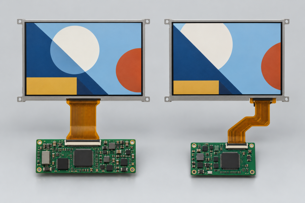
Two same-resolution TFT LCD modules showing different timing behavior
Different driver ICs
Two modules can use different timing-controller or source-driver designs. Each driver can have its own accepted blanking range, polarity, sampling edge and initialization sequence. A replacement panel may therefore need a new controller-board configuration even when the active pixels match.
Different panel architectures
Gate-driver integration, source-driver arrangement and internal timing generation can change the required input mode. An integrated timing controller can accept a different range from a module that depends more directly on external timing.
Different refresh-rate and clock ranges
A host may generate a common 60 Hz mode, but the panel datasheet can specify another typical rate or a limited allowable range. Changing the blanking while retaining 60 Hz also changes the required Pixel Clock.
Different synchronization modes
One RGB panel may use SYNC-DE mode while another uses DE-only mode. The FPC can carry similar data lines, yet the controller and pin definition still need different treatment.
Other compatibility layers
Even identical display timing does not prove full compatibility. Check the connector and pin definition, power rails, reset sequence, backlight circuit, touch interface, image orientation, driver support and mechanical fit. Timing is one system layer, not a substitute for the rest of the review.
Como a Interface Transporta o Timing
RGB paralelo
Parallel RGB makes timing easy to observe. Separate conductors commonly carry red, green and blue data together with Pixel Clock, DE and synchronization signals. The display controller produces the raster timing directly.
This visibility does not make the interface universal. Data width, color ordering, voltage, polarity, sampling edge and timing must still match.
LVDS
An LVDS transmitter serializes pixel and control information into differential pairs. The panel receiver reconstructs the data. The system still needs a valid native mode, correct LVDS mapping, suitable channel count, supported bit depth and correct clock relationship.
Pixel Clock is related to the transported pixel rate, but it is not the same value as the serial bit rate on an LVDS pair. Serialization ratio and link architecture affect the physical data rate.
MIPI DSI video mode
MIPI DSI video mode transports a video stream in packets over one or more high-speed data lanes. Active video and blanking requirements affect the data that must cross the link. Lane count, pixel format, operating mode, overhead and D-PHY settings determine whether the host has enough capacity.
The familiar RGB timing values can still appear in the host configuration, but the DSI lane clock is not simply equal to Pixel Clock. Use the SoC, bridge and panel documentation to calculate and validate the link.
MIPI DSI command mode
Command-mode panels can receive updates through display commands and may use internal frame memory. Their transfer behavior differs from a continuous parallel RGB stream. Do not apply a video-mode calculation without confirming how the selected panel and host implement command mode.
eDP and HDMI paths
eDP carries standardized packetized display data, while HDMI often appears as an input to a controller board rather than as the native interface of a bare LCD module. A board must still output a panel-supported mode on the internal display side.
An HDMI source showing the correct resolution does not prove that an HDMI-to-MIPI or HDMI-to-LVDS board can drive a given panel. The active conversion depends on the bridge, output interface, panel timing, firmware and physical connection.
Como o Blanking Afeta a Largura de Banda
Larger blanking intervals increase the horizontal or vertical total. At the same refresh rate, this raises Pixel Clock. More pixel periods per second also increase the rate at which the display pipeline must move data.
The impact extends beyond the panel connector:
The display controller must generate the required clock.
A bridge IC must accept and produce the required mode.
The physical link must provide sufficient throughput.
The framebuffer path must deliver active pixel data on time.
Memory bandwidth must support the pixel format, layers and refresh rate.
A simple framebuffer bandwidth estimate often starts with active pixels, bytes per pixel and frames per second. Real system demand can be higher because of graphics layers, memory bursts, alignment, scaling and other access. Link bandwidth calculations also include encoding or packet overhead that is specific to the interface.
Do not treat one Pixel Clock formula as a complete system bandwidth model. Use it to establish the raster rate, then check each controller, bridge, memory and physical-link limit.
Sintomas de Timing LCD Incorreto
Sintoma
Timing-related checks
Other checks
Black screen
Pixel Clock, DE, sync mode, polarity
Power, reset, initialization, data path, backlight
White screen with backlight
Valid active video and timing
Panel initialization, pinout, interface and controller support
Horizontal image shift
HFP, HBP, HSYNC and active width
Data mapping and cropping settings
Vertical image shift
VFP, VBP, VSYNC and active height
Rotation, scaling and framebuffer configuration
Cropped edge
Active area and total timing
Scaling, OSD or source-mode configuration
Repeated or wrapped region
Line or frame boundary values
Framebuffer stride and bridge configuration
Flicker
Clock stability, refresh rate, sync and DE
Power noise, backlight PWM, cable and signal integrity
Intermittent startup
Timing enable and clock startup
Power sequence, reset, firmware and temperature
These symptoms are clues, not proof. For example, flicker can come from an unstable Pixel Clock, but it can also come from the LED driver or a poor connector. Diagnose the display as a system.
Como Ler uma Tabela de Timing de LCD
Confirm the exact panel and document revision. A model suffix can identify another FPC, driver IC or timing configuration.
Find the interface mode. Identify RGB, LVDS, MIPI DSI or another path and the supported operating mode.
Record Hactive and Vactive. Do not infer them only from a marketing resolution.
Record each porch and sync width. Note whether the values are expressed in clocks or lines.
Calculate horizontal and vertical totals. Compare your results with any totals stated in the document.
Check Pixel Clock. Record typical, minimum and maximum values where provided.
Check polarity. Verify HSYNC, VSYNC, DE and clock-edge definitions.
Check setup and hold time. Compare these requirements with the host and board design.
Read the timing notes. A footnote can define dependencies that the main table does not show.
Keep the recommended mode together. Do not mix typical values from one mode with limits from another.
Como Comparar um Painel com uma Placa Controladora
1. Identify the exact hardware
Record the LCD model and revision, driver IC when available, controller-board model, bridge IC, connector and PCB revision. Compatibility cannot be confirmed from screen size and resolution alone.
2. Compare the complete panel mode
Create a table for active resolution, total resolution, porches, sync widths, refresh rate, Pixel Clock, polarity and sampling edge. Compare it with the modes that the controller or firmware can generate.
3. Check interface-specific requirements
For LVDS, include mapping, channel count and bit depth. For MIPI DSI, include lane count, pixel format, video or command mode, lane-rate limits and initialization commands. For RGB, include data width and voltage.
4. Check the clock source and divider
A processor may calculate its display clock from a parent clock and integer or fractional divider. The exact requested value may not be available. Confirm the actual generated clock and ensure that the resulting frame rate remains inside the panel limits.
5. Check firmware and operating-system support
The board support package, device tree, bootloader or controller firmware must describe the correct mode. A hardware-capable board can still fail if the software loads a default timing for another panel.
6. Check power, reset and backlight separately
Correct video timing cannot repair a wrong supply, reset pulse, initialization sequence or LED-driver mismatch. Keep these checks in the same validation plan, but do not confuse them with raster timing.
7. Validate repeated transitions
Test cold power-up, warm restart, signal reconnect, sleep, wake and controlled power-down. Observe whether the clock and active video start only after the panel is ready and whether the backlight exposes an invalid frame.
Medindo o Timing em Hardware Real
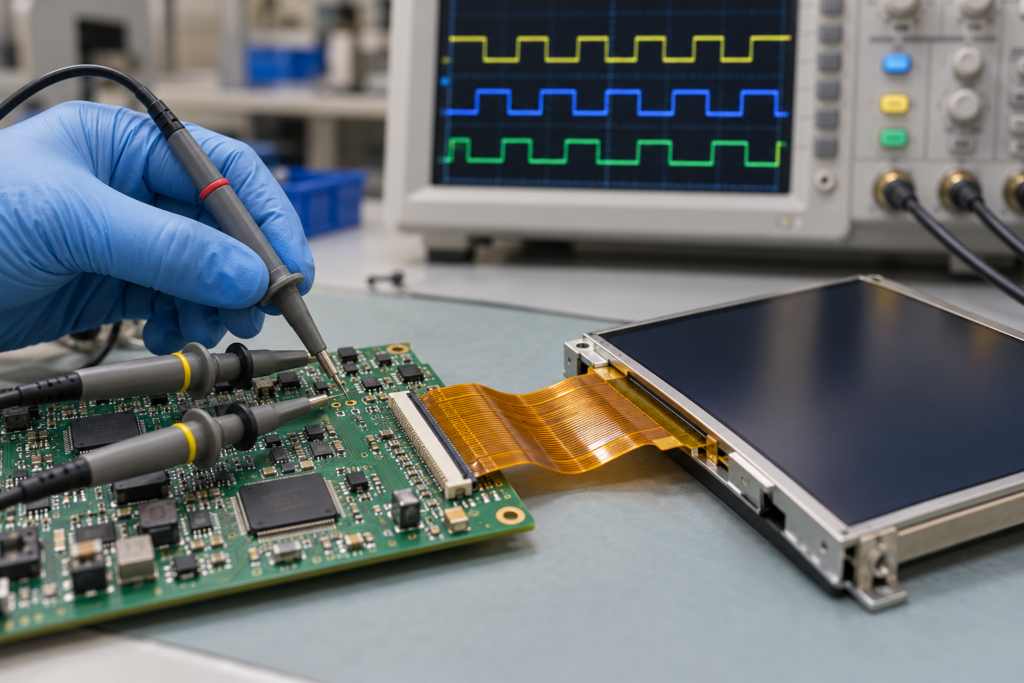
Oscilloscope probes validating signals on a TFT LCD controller board
Oscilloscope checks
On accessible parallel signals, an oscilloscope can measure Pixel Clock frequency, HSYNC rate, VSYNC rate, DE width, polarity and startup order. From the measured HSYNC and VSYNC rates, engineers can check whether the actual line and frame cadence agrees with the intended mode.
Use probes and bandwidth appropriate for the signal. Poor probing can distort an edge or add enough loading to change behavior. Differential high-speed links require suitable differential measurement equipment and methods.
Logic-analyzer checks
A logic analyzer can help with lower-speed control signals, GPIO sequencing, SPI initialization or I²C configuration. It is not automatically suitable for capturing every MIPI, LVDS or eDP physical-layer signal. Use protocol-specific equipment when the link speed and signaling method require it.
Measurement does not replace the datasheet
A measurement shows what the board generates, not what the panel accepts. Compare it with the approved specification.
Firmware, Device Tree e Configuração da Placa
A typical embedded display configuration can include:
Largura e altura ativas
Porches horizontais e verticais
HSYNC and VSYNC widths
Pixel Clock or clock-divider settings
HSYNC, VSYNC, DE and clock polarity
Pixel format and color order
LVDS mapping or MIPI lane settings
Reset and enable GPIO behavior
Comandos de inicialização do painel
Backlight enable and dimming control
Linux display drivers and device trees often store mode parameters as separate clock, active-area, margin, sync-length and polarity values. An Android-based board can use the same kernel-level configuration concepts even though the user interface runs on Android.
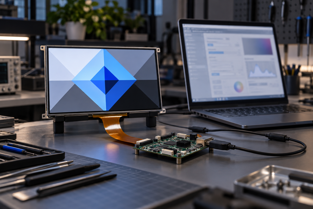
Firmware configuration test for a TFT LCD and controller board
Firmware adaptation is therefore a real part of panel matching. It should be planned with the hardware review rather than treated as a final software setting after the board is complete.
O que a RJY Display Pode Analisar
RJY Display can review display timing as part of a project-specific LCD and controller-board configuration. Depending on the selected panel and host platform, the scope can include:
Native resolution and timing-table comparison
Pixel Clock, porch, sync and polarity review
RGB, LVDS, MIPI, eDP and related interface coordination
Controller-board and bridge-path evaluation
Project-dependent firmware adaptation
FPC, connector and pin-definition coordination
Backlight, touchscreen and power review
Display-related mechanical integration
This is a compatibility process, not a universal board claim. The result depends on the exact LCD, controller hardware, firmware, operating system and application environment. An active HDMI-to-MIPI or HDMI-to-LVDS path must be designed for the selected panel; it is not a passive cable conversion.
Informações Necessárias para uma Análise de Compatibilidade de Timing
Send the following information where available:
Modelo e revisão completos do LCD
Panel datasheet and timing table
Native resolution and interface
Driver IC or timing-controller information
Pin definition and connector drawing
Pixel Clock range
Horizontal and vertical porch values
HSYNC and VSYNC widths and polarity
Controller board, processor and bridge IC
Operating system, firmware or BSP information
Backlight and touchscreen requirements
Photographs or video of the current failure
Sample quantity, expected volume and project schedule
If the current system already works with another panel, include that panel’s datasheet and approved configuration. A side-by-side comparison often shows whether the difference lies in timing, pinout, interface mode, power or software.
Use o Timing Completo, Não Apenas a Resolução
LCD pixel clock connects resolution, blanking and refresh rate, but it is not the only compatibility parameter. Engineers must also preserve the required porches, sync widths, Data Enable behavior, polarity and sampling edge. The chosen interface and firmware then need to carry or generate that mode correctly.
This is why two same-resolution panels can produce different results on the same board. Treat the panel timing table as part of the hardware specification, not as an optional software detail.
Pixel Clock is the rate at which pixel periods advance in a display timing stream. It includes active pixels and the pixel periods used by horizontal and vertical blanking.
How do I calculate LCD pixel clock?
Add the active width, horizontal porches and HSYNC width to obtain the horizontal total. Add the active height, vertical porches and VSYNC width to obtain the vertical total. Multiply both totals by the refresh rate. Then compare the result with the panel’s specified clock range.
Is pixel clock the same as refresh rate?
No. Refresh rate is the number of complete frames per second. Pixel Clock is the number of pixel periods per second. The totals for each line and frame connect the two values.
Why do two LCDs with the same resolution use different timings?
They can use different driver ICs, blanking intervals, synchronization modes, clock ranges, signal polarities and initialization requirements. Resolution describes only the active pixel matrix.
Can I change porch values if the total timing stays the same?
Do not assume so. A panel can require specific front porch, sync width and back porch ranges even when the total is unchanged. Use the exact datasheet limits and validate the complete system.
What happens when HSYNC or VSYNC polarity is wrong?
The panel may fail to recognize line or frame boundaries. Possible results include a black screen, image shift, unstable display or intermittent operation. These symptoms can also have other causes.
Does an LVDS or MIPI display still need timing configuration?
Yes. These interfaces transport display data differently from parallel RGB, but the host, bridge and panel still need a supported native mode. Link mapping, lane configuration, throughput and firmware must also match.
Can RJY match a controller board using only the LCD resolution?
No. A review also needs the LCD model, interface, pin definition, timing, driver IC when available, power, backlight, touch, firmware, operating system and application requirements.