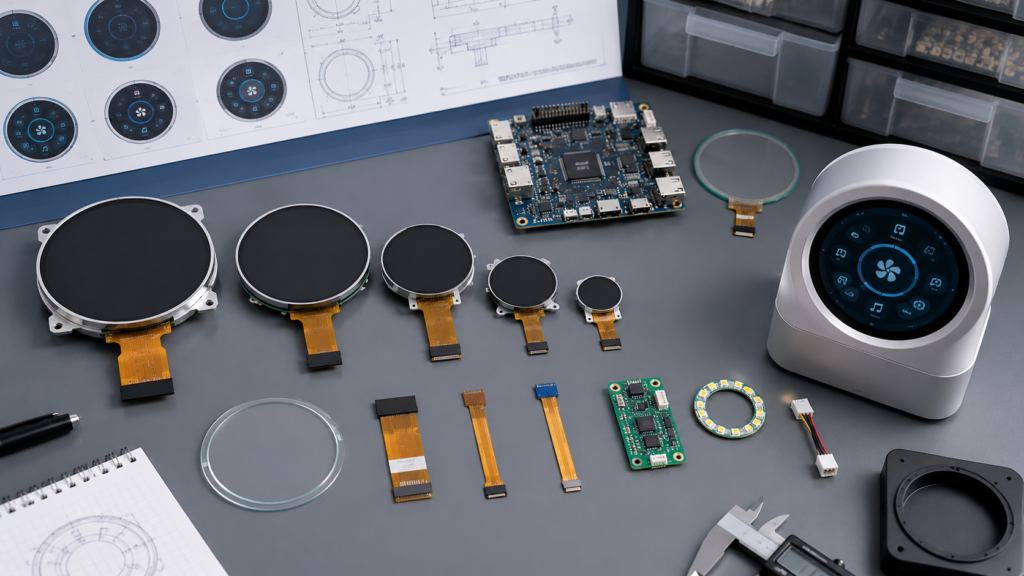
OEM製品向けのラウンドLCDディスプレイの選び方
A round LCD display can support a product architecture that would be difficult to achieve with a conventional rectangular screen. Circular control panels, instrument-style interfaces, rotary appliances, vehicle-related equipment, smart-home terminals, and specialized HMIs can all benefit from a display that follows the shape of the product.
The shape does not simplify engineering selection. A round display must still fit the enclosure, present the required information, connect to the actual host, operate with the available power and backlight circuits, support the intended touch behavior, and remain identifiable through sampling and production.
The reliable selection process begins with the complete product requirement. Diagonal size and resolution are useful filters, but they do not establish visible geometry, interface compatibility, mechanical fit, UI usability, or environmental suitability.

First Define What “Round LCD” Means
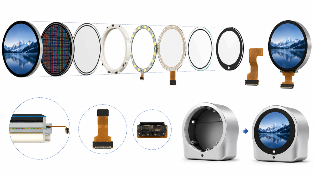
Several different structures can be described as a round LCD. The front surface may appear circular while the LCD glass, backlight frame, or pixel matrix remains square or approximately rectangular. Another assembly may use circular cover glass over a conventional display opening.
| Geometry Term | 説明内容 | その重要性 |
|---|---|---|
| アクティブエリア | The area containing addressable pixels | Determines the physical image size and visible UI canvas |
| Visible or viewing area | The area intended to remain visible through the bezel or cover | Defines where text, indicators, and controls can be seen |
| LCD glass outline | The complete dimensions of the LCD cell | Affects enclosure clearance and mounting |
| モジュール外形 | The LCD, backlight, frame, adhesive, and rear-component envelope | Determines whether the complete assembly fits |
| Touch active area | The sensor area in which input is detected | Must align with the displayed controls and coordinate system |
| カバーガラス外形 | The finished front lens visible to the user | Affects appearance, bonding, enclosure fit, and touch behavior |
Do not assume that every pixel inside a square-resolution framebuffer remains visible. Request a controlled mechanical drawing that identifies the active area, viewing boundary, glass outline, module outline, FPC, components, touch sensor, and cover glass.
Start With the User Interface and Product Architecture
A round display should be selected because it supports the product’s interaction and mechanical architecture, not only because it creates a distinctive appearance.
Document the information and controls that the user must access:
- Persistent operating status, values, warnings, and connection indicators
- Primary actions and frequently adjusted settings
- Text, icons, charts, animation, images, or video
- Required languages and longest translations
- Bare-finger, glove, stylus, encoder, button, or mixed input
- Viewing distance, mounting angle, orientation, and ambient light
- Startup, waiting, fault, maintenance, update, and recovery states
Prepare representative screens at the intended physical size before choosing the module. A visually attractive dial screen may still fail when warnings, translated text, touch targets, or diagnostic information must fit within the circular boundary.

Compare Active Diameter and Module Outline Before Diagonal Size
Diagonal size is particularly easy to misinterpret for a round display. It may refer to the panel class, active diameter, or another manufacturer-defined dimension. Two modules sold under the same nominal size can have different active areas, borders, glass outlines, frames, FPC positions, and thicknesses.
| Mechanical Check | 解決すべき質問 |
|---|---|
| Visible diameter | What circular area must remain visible through the final bezel and cover? |
| LCD and module outline | Can the cell, backlight, frame, adhesive, and components fit behind the front opening? |
| 厚み | Does the stated value include touch, cover glass, adhesive, frame, and rear components? |
| Center alignment | Are the active area, touch area, cover opening, and enclosure center concentric within the tolerance stack? |
| FPCの引き出し | Can the tail reach the PCB without conflicting with the symmetrical front design? |
| Mounting and support | Which regions can be supported or bonded without loading the active glass? |
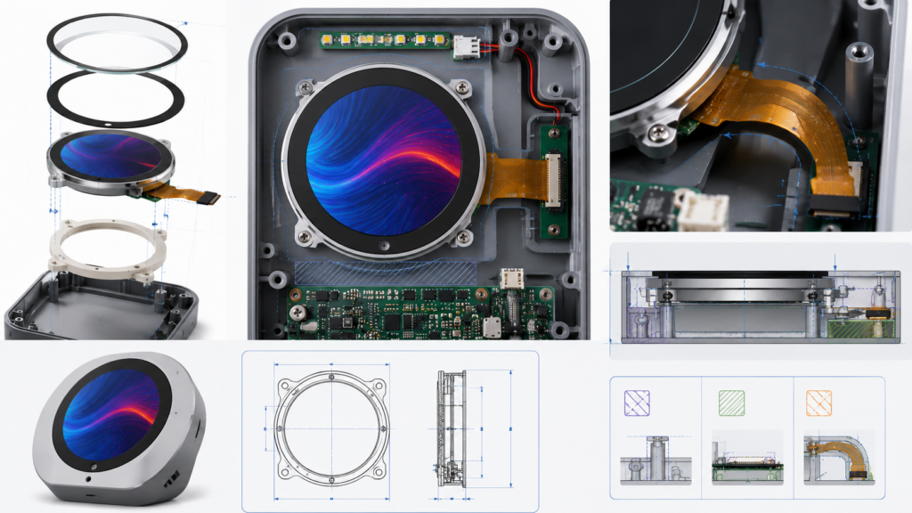
Review the supplier drawing with the enclosure CAD and PCB placement. A circular front opening does not make the internal assembly rotationally symmetrical.
Select Resolution From the UI and Host Capability
Round displays commonly use square pixel matrices because a square framebuffer can contain a circular visible image. Other products may use a pixel matrix that is not perfectly square. The exact visible boundary and pixel behavior must come from the current display documentation.
Resolution selection should consider:
| Android OS | Engineering Impact |
|---|---|
| Smallest text and indicators | Determines whether sufficient physical pixel detail is available |
| Information density | Controls how much status and control information can remain visible |
| Graphics workload | Affects rendering, framebuffer memory, transfer bandwidth, and host load |
| Localization | May require additional space, fonts, glyph memory, and line wrapping |
| アニメーションまたはビデオ | Requires representative testing of the processor, memory, interface, and software stack |
| Native orientation | Affects panel timing, application layout, touch coordinates, and boot graphics |
以下を使用すること TFT LCDパラメータ計算ツール as an initial aid for physical display calculations. Final approval must still use the current panel datasheet, real UI artwork, and target hardware.
Design a Circular UI Safe Area
A square pixel canvas does not mean that critical content should use the corners. Define an application-specific safe area inside the visible circle and keep essential text, touch targets, warning symbols, and navigation inside it.
The required margin depends on the actual visible boundary, bezel, cover-glass printing, touch alignment, font, control size, mounting accuracy, and user workflow. Do not apply one universal percentage to every round display.
| UI Element | Round-Screen Review |
|---|---|
| Primary status | Keep it visible without requiring the user to interpret clipped corner content |
| Text | Test line length, wrapping, physical size, and translations inside the circular boundary |
| Touch controls | Confirm that the complete target remains inside the visible and reliably sensed area |
| Arcs and gauges | Verify that scales, labels, endpoints, and warning zones remain readable |
| Dialogs and keyboards | Evaluate whether rectangular components need a round-specific layout |
| System screens | Include boot, update, recovery, permission, and error screens in the round-layout review |
Android supports a resource qualifier that distinguishes round from non-round screens, showing that screen shape can require platform-specific layout resources rather than simple scaling.[5] An embedded Linux, RTOS, or MCU framework may use a different implementation, but the same engineering principle applies: the application must understand the actual visible shape.
Match the Display Interface to the Actual Host
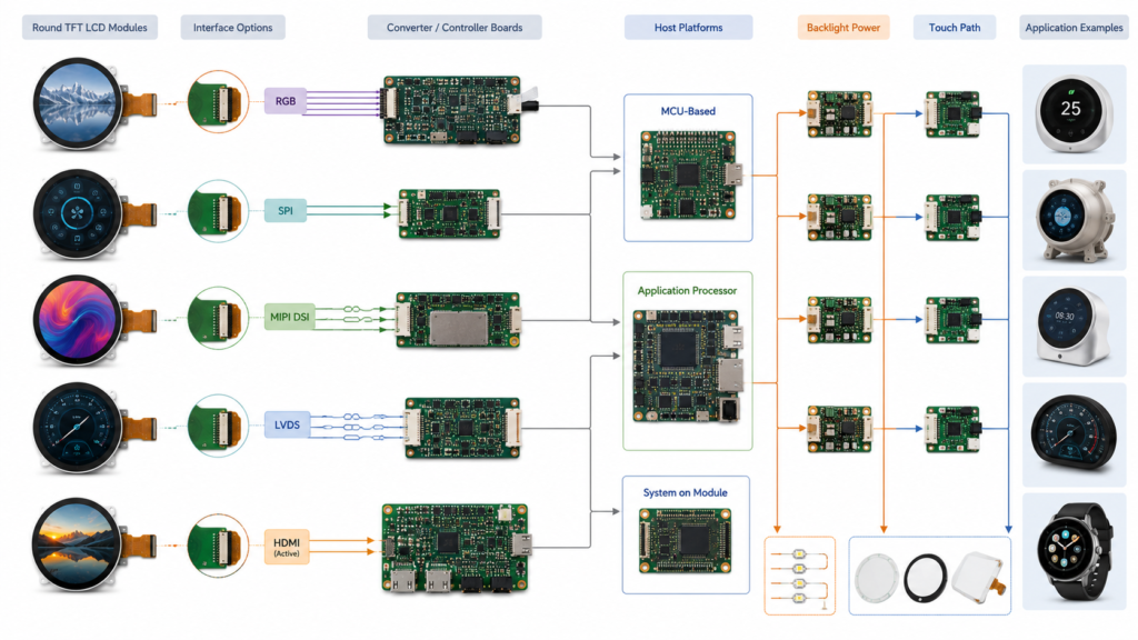
RJY Display’s current public round-display category includes product paths using RGB, RGB plus SPI, MIPI DSI, and LVDS.[1] These interface names are not interchangeable, and they do not independently prove compatibility with a host board.
| インターフェース経路 | Potential Project Context | 確認すべき項目 |
|---|---|---|
| RGB with control SPI | MCU or application-processor systems with an implemented parallel display controller | Data width, pixel clock, synchronization, voltage, initialization, pinout, memory, and PCB routing |
| MIPI DSI | Processors or bridge boards with a supported DSI Host | Implemented lanes, lane operating range, mode, pixel format, native timing, commands, power, and panel driver |
| LVDS | Larger embedded panels and supported controller-board architectures | Channel configuration, mapping, clock, color assignment, voltage, connector, cable, and timing |
| Active controller board | A host provides HDMI or another standard video mode while a controller drives the raw panel | Input mode, scaling, panel output, firmware, initialization, backlight, power, and touch return path |
MIPI Alliance defines MIPI DSI as a high-speed serial interface between a host processor and a display module.[3] A shared DSI label still requires agreement on the physical implementation, timing, operating mode, commands, power, and software.
NXP’s DSI display-system example separately configures native timing, panel power, reset, backlight control, clocks, signal polarity, and the display interface.[2] Matching the interface or resolution alone is therefore insufficient.

以下を使用すること custom MIPI TFT LCD guide when the selected round module uses DSI. For a broader comparison, see LCDディスプレイモジュールにおける一般的なインターフェース.
Start With the Actual Board, Not the Processor Brochure
A processor may contain a display controller that the finished board does not route to a connector. The board can also lack the correct voltage rails, GPIOs, backlight circuit, panel driver, or software configuration.
Before approving a round LCD, collect:
- Exact MCU, application processor, computing module, or controller-board model
- Board revision, schematic information, and connector definition
- Implemented display output and supported native timing
- Available memory and representative graphics workload
- Panel power, reset, enable, and backlight circuits
- Operating system, kernel, BSP, bootloader, RTOS, or MCU SDK version
- Existing panel driver and initialization support
- Touch input interface and driver
Compatibility should be demonstrated for the actual board, panel, cable, and software image. A processor-level interface list is only a starting point.
Evaluate Touch as a Separate Subsystem
A round LCD can be supplied without touch or coordinated with a suitable touch configuration when available. The touch sensor, controller, cover glass, bonding, FPC, host interface, and firmware must be evaluated separately from the image path.
| Touch Area | Selection Question |
|---|---|
| Sensor geometry | Does the active touch area align with the visible circle and required controls? |
| タッチコントローラー | Which exact controller and firmware are used, and which contacts and input tools are supported? |
| Host connection | Does the board provide the required USB, I2C, SPI, reset, interrupt, voltage, and driver? |
| カバーガラス | Are outline, diameter, thickness, printing, opening, adhesive area, and surface requirements defined? |
| Coordinate mapping | Do the origin, range, scaling, rotation, and circular UI agree with the displayed image? |
| 環境 | Which glove, moisture, cleaning, electrical-noise, and grounding conditions must be tested? |
Microchip’s capacitive-touch design guide explains that the touch cover affects sensor behavior and that mechanical and electrical requirements must be considered as part of sensor design.[4] Do not assume that custom circular cover glass can be added without reviewing the sensor-controller configuration.
Android also uses input-device properties and calibration to classify, transform, and normalize touch behavior, including orientation-aware coordinate mapping.[6] The final touch system should be tested with the approved cover glass, controller firmware, host driver, rotation, bezel, and enclosure.
For a complete touch review, use the タッチスクリーン付きTFT LCDモジュールガイド.
Choose Backlight and Optical Performance From the Environment
Brightness should be selected from the intended viewing condition rather than maximized by default. The finished optical path includes the LCD, polarizers, touch sensor, bonding or air gap, cover glass, printed border, surface treatment, ambient light, viewing direction, and UI colors.
| Optical Requirement | What to Evaluate |
|---|---|
| Ambient light | Installation position, reflections, cover stack, viewing distance, and screen content |
| 視野方向 | Normal user position, off-axis use, rotation, color shift, and contrast behavior |
| Backlight power | LED configuration, driver circuit, voltage, current, enable, dimming, and heat |
| Dimming | Required operating range, control method, low-level behavior, and application response |
| Cover and bonding | Reflections, appearance, contamination, alignment, adhesive, and touch performance |
Do not infer sunlight readability, outdoor suitability, optical bonding performance, or a universal lifetime from the advertised brightness of a product. Use configuration-specific data and validate the complete assembly.
Check FPC, Connector, and PCB Placement
The front of a round display may look symmetrical, but the FPC and connector create a defined orientation. Their location can determine PCB placement, mounting, cable access, and serviceability.
Review the following from controlled drawings:
- FPC exit direction, length, stiffener, contacts, and safe bend region
- Connector pitch, height, contact side, insertion direction, and mating part
- Display, control, power, ground, backlight, and touch pin assignments
- Rear components and keep-out areas
- PCB connector access during assembly
- Clearance from fasteners, edges, heat sources, antennas, and moving components
- Strain relief, retention, repeated assembly, and service procedure
A matching connector count does not prove a matching pinout. An adapter can reroute compatible signals, but it cannot add an unsupported display controller, create missing lanes, correct an incompatible voltage, or replace absent firmware.

Translate Application Labels Into Testable Requirements
Terms such as industrial round display, 自動車用ディスプレイ, outdoor HMI, and medical display do not define universal specifications. Convert the application label into measurable requirements for the exact finished equipment.
| Environment Area | Requirement to Define |
|---|---|
| 温度 | Operating and storage limits, startup condition, duration, and acceptable display and touch behavior |
| Moisture and cleaning | Exposure, sealing responsibility, cleaning agents, frequency, touch behavior, printing, and adhesives |
| Vibration and shock | Mounting, axes, profile, duration, operating state, sample configuration, and acceptance criteria |
| Electrical conditions | Power quality, grounding, cables, ESD or immunity requirements, enclosure, and operating state |
| Mechanical loading | Cover pressure, enclosure deformation, adhesive stress, fasteners, and support surfaces |
| Regulatory context | Applicable finished-product standards, responsible party, exact configuration, and required evidence |
Do not infer an automotive qualification, medical certification, IP rating, chemical resistance, or environmental grade from the display shape, product title, panel technology, or intended application.
Start With an Existing Round LCD Platform
RJY Displayの Round Display category provides existing product paths for initial review. The current public range includes small RGB-based modules, MIPI options, touch configurations, and larger LVDS or MIPI products.[1]
| Public Product Path | Published Selection Role | Documents to Request Before Approval |
|---|---|---|
| 2.1-inch round LCD | Compact RGB-plus-control-interface evaluation | Current datasheet, timing, pinout, driver IC, touch status, and drawing |
| 2.8-inch round TFT LCD | Compact round HMI or embedded-device evaluation | Exact model, interface, optional touch, backlight, and host requirements |
| 4-inch round touch TFT LCD | Touch-enabled round HMI evaluation | LCD, touch controller, cover, bonding, FPC, host driver, and mechanics |
| 7-inch round TFT LCD | Larger LVDS-based display evaluation | Channel mapping, timing, cable, power, backlight, touch option, and drawing |
| 8-inch round LCD | Larger MIPI-based application-processor evaluation | Lanes, mode, timing, initialization, board support, power, and mechanics |
These links are product-discovery paths, not automatic compatibility approvals. Public specifications should be checked against the latest controlled documents and current supply status before sampling.
Define Customization Around the Existing Module
When the core round LCD platform is suitable, a project can evaluate surrounding changes such as:
| カスタマイズ領域 | 想定されるプロジェクト範囲 | 必要な制御 |
|---|---|---|
| カバーガラス | Outline, opening, printing, thickness, edge, and surface requirements | Controlled drawing, material, tolerances, appearance criteria, and touch validation |
| タッチスクリーン | Sensor, controller, cover stack, bonding, FPC, and host connection | Exact controller, firmware, driver, coordinates, environment, and sample approval |
| バックライト | Brightness target, enable, dimming, power, and driver coordination | Electrical, optical, thermal, and mechanical validation |
| FPC and interface | Tail direction, connector, pin routing, cable, or board coordination | Electrical and mechanical drawings, tooling, firmware, and sample testing |
| コントローラ基板 | Board selection or adaptation around the confirmed panel | Actual board revision, interface, timing, firmware, touch, and backlight support |
| ファームウェア | Panel initialization, timing, UI orientation, touch, boot, sleep, and wake | Named platform, deliverables, revisions, ownership, and acceptance tests |
| 機械構造 | Cover, bezel, support, enclosure, PCB position, and cable routing | CAD, tolerance stack, assembly plan, tooling, and complete sample validation |
This customization route begins with an existing display module. It should not be interpreted as the ability to create any arbitrary round LCD diameter, resolution, or new panel architecture from scratch.
For commercial scope and cost drivers, see Why Round LCD Displays Cost More.
Use a Round LCD Comparison Matrix
| Decision Area | Candidate A | Candidate B | 必要な証拠 |
|---|---|---|---|
| Model and revision | Record | Record | Current controlled datasheet and drawing |
| Visible geometry | Compare | Compare | Active area, viewing area, cover opening, and UI artwork |
| Module envelope | Compare | Compare | LCD, backlight, frame, components, FPC, touch, and cover dimensions |
| Resolution and UI | Evaluate | Evaluate | Physical prototype, fonts, translations, controls, and system states |
| インターフェースとタイミング | 確認 | 確認 | Board-level implementation, native timing, pinout, and firmware |
| タッチ | 確認 | 確認 | Sensor, controller, cover, coordinates, driver, and required input tests |
| Backlight and optics | Evaluate | Evaluate | Configuration data and finished-product viewing test |
| 機械的適合性 | Evaluate | Evaluate | Display, PCB, cable, cover, and enclosure CAD |
| 環境 | Evaluate | Evaluate | Application-specific requirements and configuration-specific evidence |
| ライフサイクル | 確認 | 確認 | Revision, substitution, firmware, PCN, EOL, and requalification process |
A lower-cost candidate should not pass the comparison when the host interface, visible geometry, touch controller, mechanical drawing, firmware, or lifecycle remains undefined.
Validate the Complete Round Display Sample
| 検証領域 | 最小限のレビュー |
|---|---|
| Visible geometry | Active circle, bezel, cover printing, center alignment, clipped pixels, and tolerance stack |
| ユーアイ | Text, icons, gauges, dialogs, warnings, translations, boot, update, error, and recovery screens |
| Display image | Native timing, full-screen patterns, orientation, color behavior, startup, sleep, wake, and repeated restart |
| タッチ | Center, circumference, edges, rotation, required input tools, cover glass, wake, and false-touch behavior |
| Application workload | Representative graphics, communication, storage, networking, peripherals, and background activity |
| Backlight and power | Enable, dimming, intended operating level, interrupted power, current, and enclosure temperature |
| 機械的組み立て | Alignment, support, FPC routing, connector access, retention, adhesive, cable, and service procedure |
| 環境 | Defined ambient light, temperature, moisture, cleaning, mechanical, and electrical conditions |
| Configuration record | LCD, touch, cover, FPC, cable, board, firmware, backlight circuit, enclosure, and open issues |
Approve the complete hardware and software configuration rather than only the round LCD model. A later change to the display revision, driver IC, touch controller, cover glass, board, firmware, cable, backlight, or enclosure may require renewed validation.
What to Send for a Round LCD Display Review
Provide the following information for a useful recommendation and quotation:
- Target product, users, workflow, and destination markets
- Required visible diameter, active area, resolution, orientation, and module envelope
- Representative full-scale UI artwork and required system states
- Exact MCU, processor, control board, computing module, or video source
- Implemented display interface, connector, native timing, and software platform
- Touch technology, input tools, controller, host interface, and contact requirements
- Cover-glass drawing, thickness, printing, surface, and bonding requirements
- Ambient light, viewing directions, backlight, dimming, and power requirements
- FPC direction, connector position, PCB placement, and cable constraints
- Operating environment and required configuration-specific tests
- 機械図面またはエンクロージャCAD
- 試作品、パイロット、量産、および予想年間数量
- Lifecycle, change-notification, and replacement expectations
- Existing display documentation when replacing another module
Request a Round LCD Compatibility Review
RJY Display can review an existing round LCD platform against your visible area, UI, host board, interface, touch, cover glass, backlight, FPC, firmware, power, environment, and mechanical requirements.
Browse current round LCD displays, 、レビューする RJY Displayのカスタムソリューション範囲または send your UI, board, display, and enclosure documents for engineering review.
よくあるご質問
What is a round LCD display?
A round LCD display is a module designed to present a circular visible image or support a circular front-panel design. The active area, viewing area, LCD glass, module outline, touch sensor, and cover glass may have different shapes, so the exact structure must be confirmed from the mechanical drawing.
Does a round LCD always have a circular pixel matrix?
No. Many round displays use a square pixel matrix or framebuffer with a circular visible area. Other modules may use a different active-pixel structure. Confirm the active area, visible boundary, resolution, and corner behavior for the exact model.
Can I replace a rectangular LCD with a round LCD of the same diagonal size?
Not automatically. The active area, visible diameter, module outline, resolution, interface, timing, pinout, power, backlight, touch, firmware, FPC, and enclosure can all differ. The UI and mechanical structure normally require a new compatibility review.
Which interface is best for a round LCD display?
There is no universal best interface. Choose from the actual host board, native panel timing, resolution, graphics workload, connector, PCB, firmware, power, and lifecycle requirements. RGB, MIPI DSI, LVDS, and active controller-board routes create different integration work.
Can a round LCD include a touchscreen and custom cover glass?
It can when a suitable display-touch configuration is available. The sensor, controller, cover-glass outline, thickness, printing, bonding, FPC, host interface, firmware, coordinate mapping, enclosure, and required operating conditions must be evaluated together.
What information is needed for a round LCD quotation?
Provide the application, visible diameter, resolution, module envelope, UI artwork, host board, interface, touch and cover-glass requirements, backlight and power needs, FPC and connector constraints, environment, enclosure drawing, validation requirements, quantities, and lifecycle expectations.
ディスプレイプロジェクトを計画中ですか?
ディスプレイサイズ、解像度、インターフェース、輝度、タッチ要件、コントローラーボード要件、およびアプリケーション環境を共有してください。.
どのディスプレイがプロジェクトに適しているかまだお決まりでないですか?
RJYのエンジニアリングチームにご相談いただき、ディスプレイマッチング、コントローラーボードの確認、およびカスタマイズについて話し合ってください。.