Столкнулись с трудностями в проекте встраиваемого дисплея?
Не позволяйте сложной интеграции или проблемам цепочки поставок замедлить ваш выход на рынок. Забронируйте бесплатную консультацию с экспертной командой RJY для получения индивидуальной поддержки в проектировании и производстве.
Руководство по тактовой частоте пикселей и синхронизации ЖК-дисплеев: почему TFT-дисплеи с одинаковым разрешением не всегда совместимы
Published:
18 мин чтения
Updated:
Два модуля TFT LCD могут иметь одинаковое активное разрешение и использовать одно и то же семейство интерфейсов, но при этом требовать разных настроек платы контроллера. Одна панель может работать корректно, тогда как другая остаётся чёрной, смещает изображение, обрезает край, повторяет часть кадра или запускается лишь время от времени.
Недостающей информацией часто являются полные временны́е параметры дисплея. Такое разрешение, как 800 × 480, описывает видимую область пикселей. Оно не описывает интервалы горизонтального и вертикального blanking, ширину синхронизирующих импульсов, полярность сигналов, фронт выборки или требуемую пиксельную частоту LCD. Эти параметры сообщают панели, когда начинается и заканчивается каждая активная строка и каждый кадр.
Это руководство объясняет, как пиксельная частота, porches, сигналы синхронизации и Data Enable влияют на совместимость TFT LCD. Оно также предлагает практический процесс сравнения панели с платой контроллера без рассмотрения разрешения или типа разъёма как доказательства совместимости.
Что такое временны́е параметры дисплея LCD?
Контроллер дисплея отправляет данные изображения в повторяющейся последовательности. Он передаёт по одной строке за раз и объединяет строки в полный кадр. Активное изображение занимает лишь часть этой последовательности. Контроллер также формирует интервалы, которые отделяют одну строку от следующей и один кадр от следующего.
Для параллельной RGB-панели хост может представить эту структуру через Pixel Clock, горизонтальную синхронизацию, вертикальную синхронизацию и сигналы Data Enable. Другие интерфейсы упаковывают или сериализуют информацию иначе, но панели всё равно требуется допустимая кадровая последовательность и поддерживаемый собственный режим.
Область активного изображения
Активная область содержит пиксели, которые отображаются на экране. Панель 800 × 480 имеет 800 активных пиксельных позиций в каждой строке и 480 активных строк в каждом кадре. Эти значения часто называют Hactive и Vactive.
Активное разрешение легко сравнивать, поэтому в описаниях товаров ему уделяется особое внимание. Однако это лишь одна часть режима.
Общая область временны́х параметров
Каждая строка также содержит горизонтальный передний porch, интервал HSYNC и горизонтальный задний porch. Каждый кадр содержит соответствующие вертикальные интервалы. Эти неактивные периоды образуют области горизонтального и вертикального blanking.
Следовательно, контроллер должен генерировать больше пиксельных периодов, чем число видимых пикселей. Полная длина строки — это горизонтальный total. Полная высота кадра — это вертикальный total.
Почему панели нужны границы временны́х параметров
Драйвер панели должен знать, какие переданные значения относятся к видимому изображению. Ему также нужна согласованная граница между строками и кадрами. В зависимости от режима панели он использует HSYNC, VSYNC, Data Enable или комбинацию этих сигналов.
Неправильные границы могут заставить драйвер начать строку слишком рано, принять неактивные данные как пиксели или потерять выравнивание кадра. Поэтому дисплей может получать корректные данные цвета, но размещать их в неправильной части изображения.
Основные временны́е параметры TFT LCD
Параметр
Значение
Почему это важно
Hactive
Видимые пиксели в каждой строке
Задаёт ширину активного изображения
HFP
Горизонтальный передний porch
Отделяет активные данные от интервала горизонтальной синхронизации
HSYNC (горизонтальная синхронизация)
Ширина импульса горизонтальной синхронизации
Обозначает или поддерживает границу строки
HBP
Горизонтальный задний porch
Отделяет интервал синхронизации от следующей активной строки
Vactive
Видимые строки в каждом кадре
Задаёт высоту активного изображения
VFP
Вертикальный передний porch
Отделяет активный кадр от вертикальной синхронизации
VSYNC (вертикальная синхронизация)
Ширина импульса вертикальной синхронизации
Обозначает или поддерживает границу кадра
VBP
Вертикальный задний porch
Отделяет вертикальную синхронизацию от следующего активного кадра
DE
Data Enable
Определяет периоды, содержащие активные пиксели
PCLK (тактовый сигнал пикселей)
Pixel Clock
Управляет скоростью продвижения пиксельных периодов
В технических описаниях панелей не всегда используются одинаковые обозначения. Они могут описывать porch как margins или указывать только общий blanking. Следуйте определениям в точном техническом описании панели.
Что такое пиксельная частота LCD?
Пиксельная частота LCD задаёт скорость пиксельных периодов в потоке видеосинхронизации. Для типичного параллельного RGB-интерфейса контроллер выдаёт пиксельные данные, а панель выбирает эти данные по указанному фронту тактового сигнала. Один тактовый период обычно продвигает передачу на одну пиксельную позицию, включая позиции внутри интервалов blanking.
Требуемая частота зависит от горизонтального общего, вертикального общего и частоты обновления. Она не зависит только от активного разрешения.
Пиксельная частота — это не частота обновления
Частота обновления указывает, сколько полных кадров происходит каждую секунду. Пиксельная частота указывает, сколько пиксельных периодов происходит каждую секунду. Частота кадров 60 Гц не подразумевает пиксельную частоту 60 МГц. Значение частоты также зависит от того, сколько общих периодов составляют каждый кадр.
Основные соотношения:
Horizontal Total = Hactive + HFP + HSYNC + HBP
Эта формула полезна для проверки, но техническое описание панели остаётся авторитетным источником. Драйверная ИС может принимать только указанный диапазон частот или ограниченный набор комбинаций таймингов.
Практический расчёт пиксельной частоты
Рассмотрим иллюстративный тайминг 800 × 480. Следующие значения приведены только для примера расчёта. Они не являются спецификацией для продукта RJY или универсальным режимом 800 × 480.
Параметр
Иллюстративное значение
Hactive
800 пиксельных периодов
Суммарный горизонтальный blanking
256 пиксельных периодов
Горизонтальный общий
1 056 пиксельных периодов
Vactive
480 строк
Суммарный вертикальный blanking
45 строк
Вертикальный общий
525 строк
Частота обновления
60 кадров в секунду
Pixel Clock = 1 056 × 525 × 60
Если инженер рассчитывает только активные пиксели, результат будет:
800 × 480 × 60 = 23,04 МГц
Этот результат опускает все периоды blanking. В данном примере он занижает требуемую частоту более чем на 10 МГц. Это различие объясняет, почему разрешение и частота кадров сами по себе не могут определить тайминг панели.
Типичные, минимальные и максимальные значения
Многие технические описания предоставляют типичные, минимальные и максимальные значения. Значения внутри каждого отдельного диапазона не всегда создают допустимый комбинированный режим. Общая частота также должна оставаться в пределах поддерживаемого диапазона.
Начните с рекомендуемого типичного режима. Изменяйте porch, частоту или частоту обновления только тогда, когда документация панели и проект хоста допускают изменение, затем проверьте результат на полной системе.
Передний porch, задний porch и ширина синхроимпульса
Porch — это неактивный интервал рядом с областью активного видео. Эти термины произошли от таймингов растровых дисплеев, но они по-прежнему описывают структуру blanking, используемую современными цифровыми интерфейсами панелей.
Последовательность горизонтального тайминга
Строка обычно содержит активные пиксельные данные, горизонтальный передний porch, импульс HSYNC и горизонтальный задний porch. Точный порядок, показанный в техническом описании, может зависеть от точки отсчёта, используемой на диаграмме. Важно то, что хост воспроизводит требуемые размеры интервалов и полярность.
Передний porch отделяет конец активных данных от события синхронизации. Задний porch отделяет это событие от начала следующей активной строки. Ширина HSYNC определяет длительность импульса синхронизации, когда выбранный режим его использует.
Последовательность вертикального тайминга
Вертикальный тайминг следует той же концепции, но его единицы — строки, а не пиксельные тактовые импульсы. Последовательность включает активные строки, вертикальный передний porch, интервал VSYNC и вертикальный задний porch.
Почему значения porch не являются свободно взаимозаменяемыми
Два режима могут иметь одинаковый горизонтальный общий, но назначать разные значения для HFP, HSYNC и HBP. Они не обязательно ведут себя одинаково. Панель может использовать определённый фронт или интервал для сброса внутреннего счётчика строк или подготовки следующей активной области.
Не перераспределяйте значения porch только для сохранения общего значения. Подтвердите допустимые значения из таблицы таймингов панели. Если в техническом описании указан только общий blanking, запросите детальный тайминг или проверенную инициализационную ссылку у поставщика панели.
HSYNC, VSYNC и Data Enable
HSYNC определяет границы горизонтального тайминга. VSYNC определяет границы вертикального тайминга. Data Enable указывает, когда шина данных содержит активные пиксели изображения. Разные панели используют эти сигналы в разных режимах.
SYNC mode
In a synchronization-based mode, the panel uses HSYNC and VSYNC to identify line and frame timing. The controller must generate the pulse widths, porches and active periods that the panel expects.
SYNC-DE mode
In SYNC-DE mode, the panel receives synchronization signals and Data Enable. DE qualifies the active image region while HSYNC and VSYNC preserve line and frame structure.
DE-only mode
Some panels support a mode in which Data Enable defines the active region and the panel does not use external HSYNC and VSYNC inputs. This does not remove the need for correct totals and blanking. The width of DE, the gap between active lines and the gap between active frames still form a timing pattern.
A host controller can output several signals at once, but that does not prove that every connected panel can use the same configuration. Select the mode documented for the panel and connect only the signals required by that design.
Полярность сигналов и фронт выборки пикселей
Frequency and pulse width are not enough. A panel also expects each control signal to be active at a defined logic level. HSYNC, VSYNC and DE can be active high or active low. The panel may sample pixel data on the rising or falling edge of Pixel Clock.
Correct frequency, wrong polarity
If the host uses the wrong sync polarity, the panel can interpret inactive time as the sync pulse or fail to recognize the intended event. Incorrect DE polarity can mark blanking as active data and active data as blanking. The result may be a black display, an unstable frame, a shifted image or an image that appears only under some conditions.
Setup and hold time
The data bus must remain stable for a specified period before and after the sampling edge. These intervals are the setup and hold times. Long PCB routes, unsuitable level shifting, connector loss, clock skew and incorrect output-edge settings can reduce the available margin.
For higher-speed designs, a correct average clock frequency does not prove adequate signal quality. Engineers must also review waveform integrity and timing at the panel input.
Почему LCD с одинаковым разрешением могут требовать разных временны́х параметров
Resolution defines the active pixel matrix. It does not standardize the electronics around that matrix.
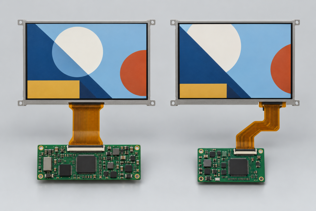
Two same-resolution TFT LCD modules showing different timing behavior
Different driver ICs
Two modules can use different timing-controller or source-driver designs. Each driver can have its own accepted blanking range, polarity, sampling edge and initialization sequence. A replacement panel may therefore need a new controller-board configuration even when the active pixels match.
Different panel architectures
Gate-driver integration, source-driver arrangement and internal timing generation can change the required input mode. An integrated timing controller can accept a different range from a module that depends more directly on external timing.
Different refresh-rate and clock ranges
A host may generate a common 60 Hz mode, but the panel datasheet can specify another typical rate or a limited allowable range. Changing the blanking while retaining 60 Hz also changes the required Pixel Clock.
Different synchronization modes
One RGB panel may use SYNC-DE mode while another uses DE-only mode. The FPC can carry similar data lines, yet the controller and pin definition still need different treatment.
Other compatibility layers
Even identical display timing does not prove full compatibility. Check the connector and pin definition, power rails, reset sequence, backlight circuit, touch interface, image orientation, driver support and mechanical fit. Timing is one system layer, not a substitute for the rest of the review.
Как интерфейс передаёт временны́е параметры
Параллельный RGB
Parallel RGB makes timing easy to observe. Separate conductors commonly carry red, green and blue data together with Pixel Clock, DE and synchronization signals. The display controller produces the raster timing directly.
This visibility does not make the interface universal. Data width, color ordering, voltage, polarity, sampling edge and timing must still match.
LVDS
An LVDS transmitter serializes pixel and control information into differential pairs. The panel receiver reconstructs the data. The system still needs a valid native mode, correct LVDS mapping, suitable channel count, supported bit depth and correct clock relationship.
Pixel Clock is related to the transported pixel rate, but it is not the same value as the serial bit rate on an LVDS pair. Serialization ratio and link architecture affect the physical data rate.
MIPI DSI video mode
MIPI DSI video mode transports a video stream in packets over one or more high-speed data lanes. Active video and blanking requirements affect the data that must cross the link. Lane count, pixel format, operating mode, overhead and D-PHY settings determine whether the host has enough capacity.
The familiar RGB timing values can still appear in the host configuration, but the DSI lane clock is not simply equal to Pixel Clock. Use the SoC, bridge and panel documentation to calculate and validate the link.
MIPI DSI command mode
Command-mode panels can receive updates through display commands and may use internal frame memory. Their transfer behavior differs from a continuous parallel RGB stream. Do not apply a video-mode calculation without confirming how the selected panel and host implement command mode.
eDP and HDMI paths
eDP carries standardized packetized display data, while HDMI often appears as an input to a controller board rather than as the native interface of a bare LCD module. A board must still output a panel-supported mode on the internal display side.
An HDMI source showing the correct resolution does not prove that an HDMI-to-MIPI or HDMI-to-LVDS board can drive a given panel. The active conversion depends on the bridge, output interface, panel timing, firmware and physical connection.
Как blanking влияет на полосу пропускания
Larger blanking intervals increase the horizontal or vertical total. At the same refresh rate, this raises Pixel Clock. More pixel periods per second also increase the rate at which the display pipeline must move data.
The impact extends beyond the panel connector:
The display controller must generate the required clock.
A bridge IC must accept and produce the required mode.
The physical link must provide sufficient throughput.
The framebuffer path must deliver active pixel data on time.
Memory bandwidth must support the pixel format, layers and refresh rate.
A simple framebuffer bandwidth estimate often starts with active pixels, bytes per pixel and frames per second. Real system demand can be higher because of graphics layers, memory bursts, alignment, scaling and other access. Link bandwidth calculations also include encoding or packet overhead that is specific to the interface.
Do not treat one Pixel Clock formula as a complete system bandwidth model. Use it to establish the raster rate, then check each controller, bridge, memory and physical-link limit.
Симптомы некорректных временны́х параметров LCD
Симптом
Timing-related checks
Other checks
Black screen
Pixel Clock, DE, sync mode, polarity
Power, reset, initialization, data path, backlight
White screen with backlight
Valid active video and timing
Panel initialization, pinout, interface and controller support
Horizontal image shift
HFP, HBP, HSYNC and active width
Data mapping and cropping settings
Vertical image shift
VFP, VBP, VSYNC and active height
Rotation, scaling and framebuffer configuration
Cropped edge
Active area and total timing
Scaling, OSD or source-mode configuration
Repeated or wrapped region
Line or frame boundary values
Framebuffer stride and bridge configuration
Flicker
Clock stability, refresh rate, sync and DE
Power noise, backlight PWM, cable and signal integrity
Intermittent startup
Timing enable and clock startup
Power sequence, reset, firmware and temperature
These symptoms are clues, not proof. For example, flicker can come from an unstable Pixel Clock, but it can also come from the LED driver or a poor connector. Diagnose the display as a system.
Как читать таблицу временны́х параметров LCD
Confirm the exact panel and document revision. A model suffix can identify another FPC, driver IC or timing configuration.
Find the interface mode. Identify RGB, LVDS, MIPI DSI or another path and the supported operating mode.
Record Hactive and Vactive. Do not infer them only from a marketing resolution.
Record each porch and sync width. Note whether the values are expressed in clocks or lines.
Calculate horizontal and vertical totals. Compare your results with any totals stated in the document.
Check Pixel Clock. Record typical, minimum and maximum values where provided.
Check polarity. Verify HSYNC, VSYNC, DE and clock-edge definitions.
Check setup and hold time. Compare these requirements with the host and board design.
Read the timing notes. A footnote can define dependencies that the main table does not show.
Keep the recommended mode together. Do not mix typical values from one mode with limits from another.
Как сравнить панель с платой контроллера
1. Identify the exact hardware
Record the LCD model and revision, driver IC when available, controller-board model, bridge IC, connector and PCB revision. Compatibility cannot be confirmed from screen size and resolution alone.
2. Compare the complete panel mode
Create a table for active resolution, total resolution, porches, sync widths, refresh rate, Pixel Clock, polarity and sampling edge. Compare it with the modes that the controller or firmware can generate.
3. Check interface-specific requirements
For LVDS, include mapping, channel count and bit depth. For MIPI DSI, include lane count, pixel format, video or command mode, lane-rate limits and initialization commands. For RGB, include data width and voltage.
4. Check the clock source and divider
A processor may calculate its display clock from a parent clock and integer or fractional divider. The exact requested value may not be available. Confirm the actual generated clock and ensure that the resulting frame rate remains inside the panel limits.
5. Check firmware and operating-system support
The board support package, device tree, bootloader or controller firmware must describe the correct mode. A hardware-capable board can still fail if the software loads a default timing for another panel.
6. Check power, reset and backlight separately
Correct video timing cannot repair a wrong supply, reset pulse, initialization sequence or LED-driver mismatch. Keep these checks in the same validation plan, but do not confuse them with raster timing.
7. Validate repeated transitions
Test cold power-up, warm restart, signal reconnect, sleep, wake and controlled power-down. Observe whether the clock and active video start only after the panel is ready and whether the backlight exposes an invalid frame.
Измерение временны́х параметров на реальном оборудовании
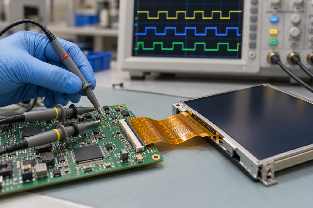
Oscilloscope probes validating signals on a TFT LCD controller board
Oscilloscope checks
On accessible parallel signals, an oscilloscope can measure Pixel Clock frequency, HSYNC rate, VSYNC rate, DE width, polarity and startup order. From the measured HSYNC and VSYNC rates, engineers can check whether the actual line and frame cadence agrees with the intended mode.
Use probes and bandwidth appropriate for the signal. Poor probing can distort an edge or add enough loading to change behavior. Differential high-speed links require suitable differential measurement equipment and methods.
Logic-analyzer checks
A logic analyzer can help with lower-speed control signals, GPIO sequencing, SPI initialization or I²C configuration. It is not automatically suitable for capturing every MIPI, LVDS or eDP physical-layer signal. Use protocol-specific equipment when the link speed and signaling method require it.
Measurement does not replace the datasheet
A measurement shows what the board generates, not what the panel accepts. Compare it with the approved specification.
Прошивка, device tree и конфигурация платы
A typical embedded display configuration can include:
Активная ширина и высота
Горизонтальные и вертикальные пороги
HSYNC and VSYNC widths
Pixel Clock or clock-divider settings
HSYNC, VSYNC, DE and clock polarity
Pixel format and color order
LVDS mapping or MIPI lane settings
Reset and enable GPIO behavior
Команды инициализации панели
Backlight enable and dimming control
Linux display drivers and device trees often store mode parameters as separate clock, active-area, margin, sync-length and polarity values. An Android-based board can use the same kernel-level configuration concepts even though the user interface runs on Android.
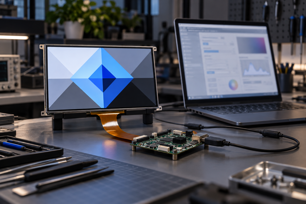
Firmware configuration test for a TFT LCD and controller board
Firmware adaptation is therefore a real part of panel matching. It should be planned with the hardware review rather than treated as a final software setting after the board is complete.
Что может проверить RJY Display
RJY Display can review display timing as part of a project-specific LCD and controller-board configuration. Depending on the selected panel and host platform, the scope can include:
Native resolution and timing-table comparison
Pixel Clock, porch, sync and polarity review
RGB, LVDS, MIPI, eDP and related interface coordination
Controller-board and bridge-path evaluation
Project-dependent firmware adaptation
FPC, connector and pin-definition coordination
Backlight, touchscreen and power review
Display-related mechanical integration
This is a compatibility process, not a universal board claim. The result depends on the exact LCD, controller hardware, firmware, operating system and application environment. An active HDMI-to-MIPI or HDMI-to-LVDS path must be designed for the selected panel; it is not a passive cable conversion.
Информация, необходимая для проверки совместимости временны́х параметров
Send the following information where available:
Полную модель и ревизию ЖК-дисплея
Panel datasheet and timing table
Native resolution and interface
Driver IC or timing-controller information
Pin definition and connector drawing
Pixel Clock range
Horizontal and vertical porch values
HSYNC and VSYNC widths and polarity
Controller board, processor and bridge IC
Operating system, firmware or BSP information
Backlight and touchscreen requirements
Photographs or video of the current failure
Sample quantity, expected volume and project schedule
If the current system already works with another panel, include that panel’s datasheet and approved configuration. A side-by-side comparison often shows whether the difference lies in timing, pinout, interface mode, power or software.
Используйте полные временны́е параметры, а не только разрешение
LCD pixel clock connects resolution, blanking and refresh rate, but it is not the only compatibility parameter. Engineers must also preserve the required porches, sync widths, Data Enable behavior, polarity and sampling edge. The chosen interface and firmware then need to carry or generate that mode correctly.
This is why two same-resolution panels can produce different results on the same board. Treat the panel timing table as part of the hardware specification, not as an optional software detail.
Pixel Clock is the rate at which pixel periods advance in a display timing stream. It includes active pixels and the pixel periods used by horizontal and vertical blanking.
How do I calculate LCD pixel clock?
Add the active width, horizontal porches and HSYNC width to obtain the horizontal total. Add the active height, vertical porches and VSYNC width to obtain the vertical total. Multiply both totals by the refresh rate. Then compare the result with the panel’s specified clock range.
Is pixel clock the same as refresh rate?
No. Refresh rate is the number of complete frames per second. Pixel Clock is the number of pixel periods per second. The totals for each line and frame connect the two values.
Why do two LCDs with the same resolution use different timings?
They can use different driver ICs, blanking intervals, synchronization modes, clock ranges, signal polarities and initialization requirements. Resolution describes only the active pixel matrix.
Can I change porch values if the total timing stays the same?
Do not assume so. A panel can require specific front porch, sync width and back porch ranges even when the total is unchanged. Use the exact datasheet limits and validate the complete system.
What happens when HSYNC or VSYNC polarity is wrong?
The panel may fail to recognize line or frame boundaries. Possible results include a black screen, image shift, unstable display or intermittent operation. These symptoms can also have other causes.
Does an LVDS or MIPI display still need timing configuration?
Yes. These interfaces transport display data differently from parallel RGB, but the host, bridge and panel still need a supported native mode. Link mapping, lane configuration, throughput and firmware must also match.
Can RJY match a controller board using only the LCD resolution?
No. A review also needs the LCD model, interface, pin definition, timing, driver IC when available, power, backlight, touch, firmware, operating system and application requirements.